EPSON AcuLaser C4000/C4100/C3000
Revision F
Disassembly and Assembly
Disassembly Assembly Procedures
4-417
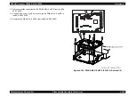
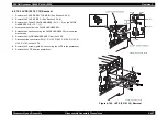
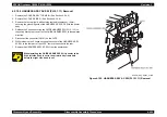
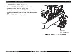
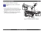
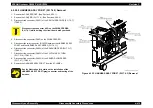
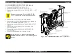
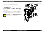
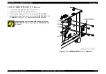
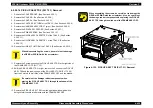
4.2.20.3 COVER L (PL17.1.1) Removal
1. Remove the COVER FRONT. (See Section 4.2.20.1.)
2. Remove the 5 screws (silver, with the brim, 8mm) securing the COVER L
to the TWO TRAY MODULE.
3. Use two hands to grasp both sides of COVER L, and while pulling front
part wider to the left and right, release the 3 bosses of front part COVER L
from the holes of FRAME ASSY OPF (PL17.1.3).
4. Lift the COVER L a little, release 4 hooks from the hooking holes of
FRAME ASSY OPF, remove the COVER L from the TWO TRAY
MODULE.
Figure 4-120. COVER L (PL17.1.1) Removal
HANABI_BE_CHAP03_045FC
REAR
Summary of Contents for AcuLaser C3000 Series
Page 20: ...C H A P T E R 1 PRODUCTDESCRIPTIONS ...
Page 71: ...C H A P T E R 2 OPERATINGPRINCIPLES ...
Page 118: ...C H A P T E R 3 TROUBLESHOOTING ...
Page 318: ...C H A P T E R 4 DISASSEMBLYANDASSEMBLY ...
Page 472: ...C H A P T E R 5 ADJUSTMENT ...
Page 477: ...C H A P T E R 6 MAINTENANCE ...
Page 491: ...C H A P T E R 7 AcuLaserC4100 ...
Page 548: ......
Page 549: ......
Page 550: ......
Page 551: ......
Page 552: ......
Page 553: ......
Page 554: ......
Page 555: ...C H A P T E R 8 AcuLaserC3000 ...
Page 579: ...Model AcuLaser C3000 Board C569MAIN BOARD Sheet 1 of 5 Rev B ...
Page 580: ...Model AcuLaser C3000 Board C569MAIN BOARD Sheet 2 of 5 Rev B ...
Page 581: ...Model AcuLaser C3000 Board C569MAIN BOARD Sheet 3 of 5 Rev B ...
Page 582: ...Model AcuLaser C3000 Board C569MAIN BOARD Sheet 4 of 5 Rev B ...
Page 583: ...Model AcuLaser C3000 Board C569MAIN BOARD Sheet 5 of 5 Rev B ...
Page 584: ...C H A P T E R 9 APPENDIX ...
Page 674: ......
Page 675: ......
Page 676: ......
Page 677: ......
Page 678: ......
Page 679: ......
Page 680: ......


