EPSON AcuLaser C4000/C4100/C3000
Revision F
Disassembly and Assembly
Disassembly Assembly Procedures
4-430
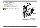
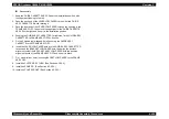
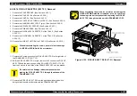
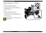
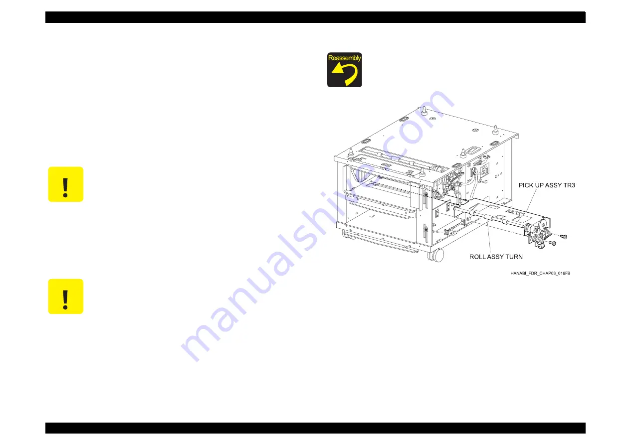
4.2.20.15 PICK UP ASSY TR3 (PL17.3.1) Removal
1. Remove the COVER FRONT. (See Section 4.2.20.1.)
2. Remove the COVER R. (See Section 4.2.20.2.)
3. Remove the COVER L. (See Section 4.2.20.3.)
4. Remove the CHUTE ASSY TURN of the TRAY 3. (See Section 4.2.20.4.)
5. Remove the HARNESS ASSY FDR 3T (blue). (See Section 4.2.20.6.)
6. Remove the GUIDE ASSY CASSETTE R. (See Section 4.2.20.11.)
7. Remove the GUIDE ASSY CASSETTE L. (See Section 4.2.20.12.)
8. Remove the LINK ACTUATOR. (See Section 4.2.20.13.)
9. Remove the 2 screws (silver, 6mm) securing the PICK UP ASSY TR 3 to
the right side of the FRAME ASSY OPF (PL17.1.3).
10. Shift the PICK UP ASSY TR 3 to right, remove the 2 hooks of the PICK UP
ASSY TR2 and the leading edge of the ROLL ASSY TURN (PL17.3.20)
from the 2 slots in the left side of the FRAME ASSY OPF and the window.
11. Remove the PICK UP ASSY TR 3 from the right side window part while
being careful to avoid interference with the FRAME ASSY OPF.
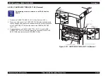
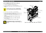
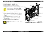
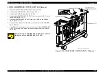
Figure 4-133. PICK UP ASSY TR3 (PL17.3.1) Removal
C A U T I O N
When disassembling the screws, be careful not to damage
the GEAR or SPRING with the screwdriver.
C A U T I O N
Be careful not the damage rubber components when
placing the PICK UP ASSY TR 2 through the window of the
FRAME ASSY OPF.
When assembling the screws, be careful not to damage the
GEAR or SPRING with the screwdriver. Also, be careful not
the damage rubber components when placing the PICK UP
ASSY TR3 through the window of the FRAME ASSY OPF.
Summary of Contents for AcuLaser C3000 Series
Page 20: ...C H A P T E R 1 PRODUCTDESCRIPTIONS ...
Page 71: ...C H A P T E R 2 OPERATINGPRINCIPLES ...
Page 118: ...C H A P T E R 3 TROUBLESHOOTING ...
Page 318: ...C H A P T E R 4 DISASSEMBLYANDASSEMBLY ...
Page 472: ...C H A P T E R 5 ADJUSTMENT ...
Page 477: ...C H A P T E R 6 MAINTENANCE ...
Page 491: ...C H A P T E R 7 AcuLaserC4100 ...
Page 548: ......
Page 549: ......
Page 550: ......
Page 551: ......
Page 552: ......
Page 553: ......
Page 554: ......
Page 555: ...C H A P T E R 8 AcuLaserC3000 ...
Page 579: ...Model AcuLaser C3000 Board C569MAIN BOARD Sheet 1 of 5 Rev B ...
Page 580: ...Model AcuLaser C3000 Board C569MAIN BOARD Sheet 2 of 5 Rev B ...
Page 581: ...Model AcuLaser C3000 Board C569MAIN BOARD Sheet 3 of 5 Rev B ...
Page 582: ...Model AcuLaser C3000 Board C569MAIN BOARD Sheet 4 of 5 Rev B ...
Page 583: ...Model AcuLaser C3000 Board C569MAIN BOARD Sheet 5 of 5 Rev B ...
Page 584: ...C H A P T E R 9 APPENDIX ...
Page 674: ......
Page 675: ......
Page 676: ......
Page 677: ......
Page 678: ......
Page 679: ......
Page 680: ......


