EPSON AcuLaser C4000/C4100/C3000
Revision F
Appendix
Wiring Diagrams and Signal Information
9-646
9.6 Wiring Diagrams and Signal Information
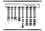
9.6.1 Overall Wiring Connection Diagram
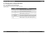
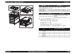
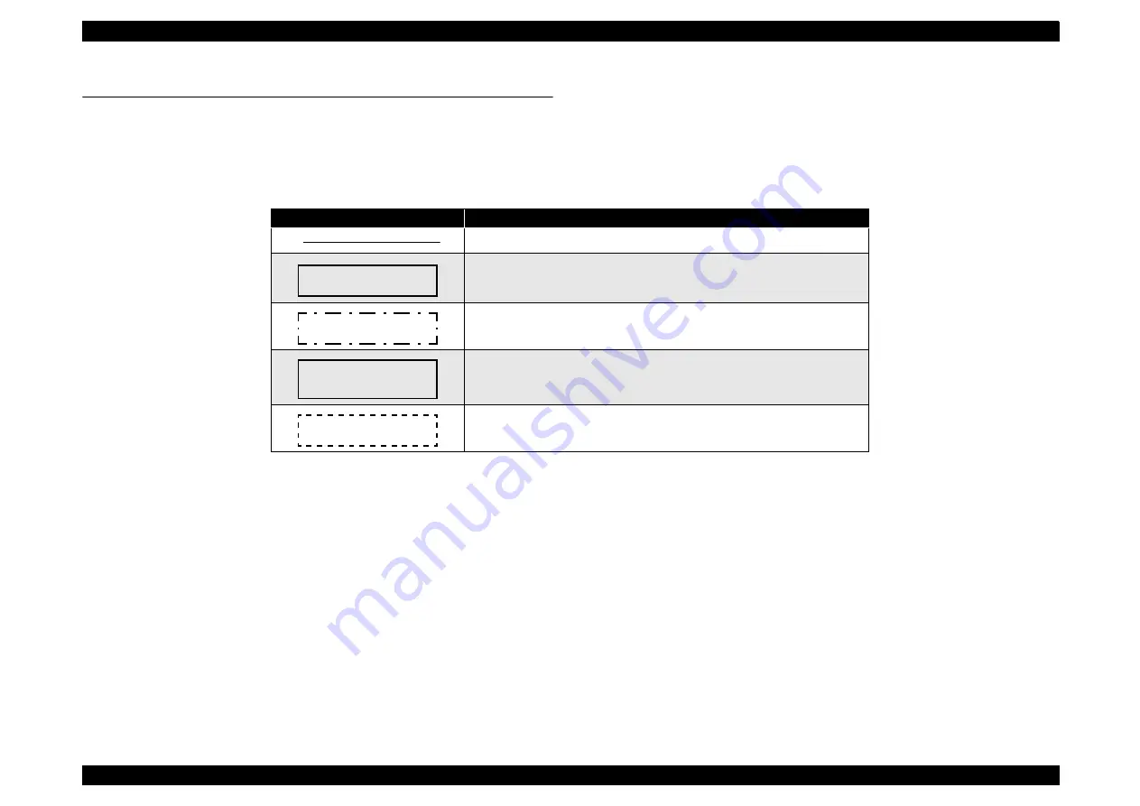
The symbols used in the overall wiring connection diagrams on the following
pages are as follows:
Symbols
Description
Indicates connection of parts by HARNESS, wire, etc.
A box with no part name inside indicates a path by a connector (P/J). A
number inside the box indicates connector number.
Indicates a connector (P/J) written across several locations. The number
inside the box indicates connector number.
Boxes with part names inside indicate those parts. The part name shown
here indicates item Z of plate (PL) XY in Section 9.4.2 "Parts List Tables".
Indicates a section in Section 9.6.2 "Wiring and Signal Descriptions
between Components". The number inside indicates the section number.
XX
XX
MCU PWB
PL X, Y, Z
§
1
Summary of Contents for AcuLaser C3000 Series
Page 20: ...C H A P T E R 1 PRODUCTDESCRIPTIONS ...
Page 71: ...C H A P T E R 2 OPERATINGPRINCIPLES ...
Page 118: ...C H A P T E R 3 TROUBLESHOOTING ...
Page 318: ...C H A P T E R 4 DISASSEMBLYANDASSEMBLY ...
Page 472: ...C H A P T E R 5 ADJUSTMENT ...
Page 477: ...C H A P T E R 6 MAINTENANCE ...
Page 491: ...C H A P T E R 7 AcuLaserC4100 ...
Page 548: ......
Page 549: ......
Page 550: ......
Page 551: ......
Page 552: ......
Page 553: ......
Page 554: ......
Page 555: ...C H A P T E R 8 AcuLaserC3000 ...
Page 579: ...Model AcuLaser C3000 Board C569MAIN BOARD Sheet 1 of 5 Rev B ...
Page 580: ...Model AcuLaser C3000 Board C569MAIN BOARD Sheet 2 of 5 Rev B ...
Page 581: ...Model AcuLaser C3000 Board C569MAIN BOARD Sheet 3 of 5 Rev B ...
Page 582: ...Model AcuLaser C3000 Board C569MAIN BOARD Sheet 4 of 5 Rev B ...
Page 583: ...Model AcuLaser C3000 Board C569MAIN BOARD Sheet 5 of 5 Rev B ...
Page 584: ...C H A P T E R 9 APPENDIX ...
Page 674: ......
Page 675: ......
Page 676: ......
Page 677: ......
Page 678: ......
Page 679: ......
Page 680: ......


