background image

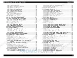
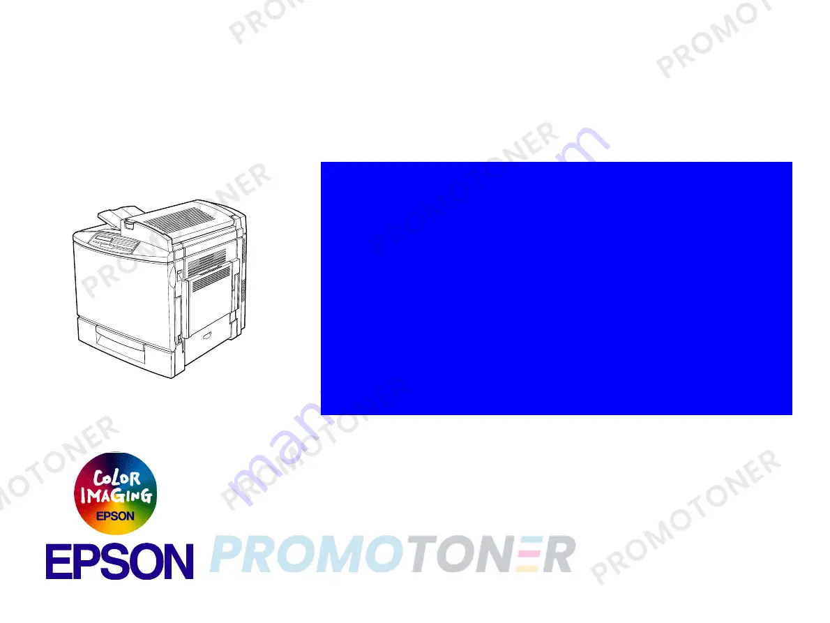
EPSON ACULASER COLOR 2000

ACULASER COLOR 1000

A4 Color Laser Printer

SEPG00004

®

SERVICE MANUAL

Summary of Contents for ACULASER COLOR 1000

Page 1: ...EPSON ACULASERCOLOR2000 ACULASERCOLOR1000 A4 Color Laser Printer SEPG00004 SERVICE MANUAL ...

Page 2: ...owever should any errors be detected SEIKO EPSON would greatly appreciate being informed of them The above not withstanding SEIKO EPSON CORPORATION can assume no responsibility for any errors in this manual or the consequences thereof EPSON is a registered trademark of SEIKO EPSON CORPORATION General Notice Other product names used herein are for identification purpose only and may be trademarks o...

Page 3: ...NOT CONNECT THE UNIT TO A POWER SOURCE UNTIL INSTRUCTED TO DO SO WHEN THE POWER SUPPLY CABLE MUST BE CONNECTED USE EXTREME CAUTION IN WORKING ON POWER SUPPLY AND OTHER ELECTRONIC COMPONENTS WARNING 1 REPAIRS ON EPSON PRODUCT SHOULD BE PERFORMED ONLY BY AN EPSON CERTIFIED REPAIR TECHNICIAN 2 MAKE CERTAIN THAT THE SOURCE VOLTAGES IS THE SAME AS THE RATED VOLTAGE LISTED ON THE SERIAL NUMBER RATING PL...

Page 4: ...hese when you are working with the printer Power Supply and Other Electrical Devices Before starting any service procedure switch off the printer power and unplug the power cord from the wall outlet If you must service the printer when the power is applied be aware of the potential for electrical shock and do all tasks by following the procedures in this manual Mechanical Components If you service...

Page 5: ... fuses interlock switches covers and panels are all functioning properly after you have reinstalled or replaced them Warning Caution Label WARNING and CAUTION labels are stuck on dangerous parts in the printer to make you aware of the potential dangers that are present when you are working with those parts W A R N I N G The laser beam used for exposing process during printing is a very powerful st...

Page 6: ... servicing the product APPENDIX Provides the following additional information for reference Connector pin assignments Electric circuit boards components layout Electrical circuit boards schematics Exploded diagram Parts List Symbols Used in this Manual Various symbols are used throughout this manual either to provide additional information on a specific topic or to warn of possible danger present ...

Page 7: ...CU Firmware Update is deleted This function is not supported for mass production D February 27 2001 3 2 4 1 Engine Related Service Call Error Messages E021 is added Transfer Belt Cleaner gap control malfunction E020 and E032 Explanation is corrected retraction gap control E October 10 2001 A new model AcuLaser C1000 has been added In connection with the addition of the new model the contents of th...

Page 8: ...t AcuLaser C2000 40 1 4 5 Explanation of Each Setting Menu and Items AcuLaser C2000 48 1 4 5 1 Printing Menu AcuLaser C2000 48 1 4 5 2 Tray Menu AcuLaser C2000 48 1 4 5 3 Config Menu AcuLaser C2000 49 1 4 5 4 Setup Menu AcuLaser C2000 50 1 4 5 5 Maintenance Menu AcuLaser C2000 51 1 4 6 Service Operations AcuLaser C2000 51 1 5 Control Panel AcuLaser C1000 53 1 5 1 Exterior View and Names AcuLaser C...

Page 9: ...er Message 108 3 2 1 Messages 108 3 2 1 1 Printer Messages on AcuLaser C2000 108 3 2 1 2 Printer Status of AcuLaser C1000 111 3 2 2 Printer Message Details of Status Messages and Remedies 112 3 2 2 1 Details of Status Messages and Remedy AcuLaser C2000 112 3 2 2 2 Details of Status Messages and Processing AcuLaser C1000 113 3 2 3 Details of Error Messages and Remedies 114 3 2 3 1 Details of Error ...

Page 10: ...ansfer Mechanism 162 4 2 17 1 Timing Roller Solenoid Removal 162 4 2 17 2 Middle Roller Solenoid Removal 162 4 2 17 3 Lower Paper Load Guide Removal 163 4 2 17 4 Timing Sensor Removal 163 4 2 18 OHP Sensor Removal 163 4 2 19 Developer Mechanism 164 4 2 19 1 Toner Empty Sensor Removal 164 4 2 19 2 Front Side Rack Bearing Removal 164 4 2 19 3 Rack Lock Lever Removal 165 4 2 19 4 Rack Black Position ...

Page 11: ...183 5 2 USB ID Input Only for AcuLaser C1000 184 5 2 1 Installation Procedure for Program 184 5 2 2 Procedure for Program Operation 184 5 2 3 USB ID Confirmation 186 Chapter 6 Maintenance 6 1 Maintenance 189 6 1 1 Replacement Parts 189 6 1 2 Cleaning 189 Chapter 7 Appendix 7 1 Overview 191 7 1 1 MCU Internal Connection Diagram 191 7 2 Component Layout 194 7 3 Exploded Diagram 199 7 4 Parts List 21...

Page 12: ...C H A P T E R 1 PRODUCTDESCRIPTIONS ...

Page 13: ...nductor unit Waste Toner Collector and Print Head Filter included Fuser Oil Roll Fuser Kit Fuser unit 2nd Transfer Roll included Transfer Belt Unit Waste Toner Collector Can be supplied separately 6 Standard paper feed includes 2 bins MP tray up to 150 sheets and Lower cassette up to 500 sheets A4 LT Including the optional single Lower cassette up to 500 sheets A4 LT paper feeding of up to 1150 sh...

Page 14: ... Color TBD Automatic color adjustment at powering on when cover is closed excludes paper jam at a time after 24hours passed or 100 pages printed since color adjustment have been done previously and returning from standby 2 Job management TBD Printing status confirmation and job cancel are enabled for job printed from built in network by EPSON Direct Print and internal network 3 Through bi directio...

Page 15: ...eet only when Type B Level3 installed PS3 Status Sheet only when PostScript3 module installed Font Sample for each mode Hex dump Support Mode Maintenance Mode Engine Status Sheet for printer engine AcuLaser C1000 ESC PageS installed Color supported Duplex printing supported Network compatibility Background job commands establish network connection ...

Page 16: ...EPSON AcuLaser C2000 AcuLaser C1000 Revision E Product Descriptions Overview 16 Exterior View and Names 1 External view 2 When open all covers except Front cover 3 When open the Front cover ...

Page 17: ... installing 256MB to both slots ROM 32bit width Program 4MB Flash ROM DIMM Fonts 4MB Expansion ROM 2 slots ROM DIMM slots can be installed and removed only with power off A B slot PS3 font ROM module Overlay ROM module Host Interface Standard Parallel 1ch Bi directional based on IEEE 1284 standard B type connector Compatibility Nibble ECP Ethernet 100Base TX 10Base T Optional Type B 1 slot Level3 ...

Page 18: ...y Nibble ECP Serial USB 1 1 1ch Optional Type B 1 slot compatible with Level 2 However Leo2 1 only Printer Mode ESC PageS Printing System Installation Method Fixed to main unit 1 2 2 Engine Specifications Printing Method Electrophotographic method using scanning semiconductor laser beam and dry one component toner Resolution 600 dpi switching with engine Print Mode B W mode Monochrome mode Offerin...

Page 19: ...c Half speed mode 29 sec 28 sec 28 sec Color Standard mode 25 sec 25 sec 25 sec 37 sec Half speed mode 38 sec 38 sec 37 sec Table 1 3 Paper Supply Paper feed method Capacity Paper size Paper thickness Standard tray 1 Standard universal tray 150 sheets Paper Width 92 to 216 mm Paper Length 210 to 297 mm 60 to 90 g m2 recommended paper plain paper 10 sheets Envelope TBD 2 50 sheets 92 x 148 to 216 x...

Page 20: ...End guide combined with paper size detectors and can be adjusted by user Maximum 2 cassette units can be installed and the maximum paper capacity is 1150 sheets 4 Each cassette is equipped with paper out sensor and near empty sensor Near empty is detected when paper remaining is 50 30 sheets when using plain paper of 80g m Table 1 4 Paper Size Paper Type Paper Size Paper Set Direction Duplex Avail...

Page 21: ...t installed 496 1 W x 548 D x 511 H mm With optional cassette installed 463 1 W x 548 D x 625 H mm With both of optional cassette and Duplex unit installed 496 1 W x 548 D x 625 H Weight Main unit only 44 5kg includes consumables Duplex unit 3 0kg Power Supply 100 120V version 100 120V 10 50 60Hz 3Hz 200V version 220V 240V 10 50 60Hz 3Hz Special Paper Envelopes COM10 104 8 x 241 3mm 4 13 x 9 5 SEF...

Page 22: ...c method using dry one component developing and Belt transfer Light source Semiconductor Laser Photoconductor unit OPC Organic Photo Conductor Drum Charging Needle electrode charger Developing Exposed area development Toner Non magnetic toner Primary transfer Roller Transfer Fixing Heated belt fixing method with oil coated mechanism Density adjustment Automatic non user adjustable Table 1 5 Power ...

Page 23: ...hick or extra thin paper Damp paper Surface coated paper or surface treated color paper Extra smooth or glossy paper Extra rough paper Paper with significantly different roughness on each surface Paper with punched holes or perforations Folded curled or torn paper Irregularly shaped paper or paper with non perpendicular corners Sheets of labels that peel off easily Paper with glue staples or clips...

Page 24: ...ethod Comments Mounted unmounted Electrical contact detection method New product Fuse method Cut fuse in new product Mounted unmounted detection at powering on Electrical contact detection method Can be mounted unmounted while power is on No damage on mechanism Status is updated when the cover is closed Consumption Calculate operating time motor rotation time Added up in 30 sec unit Near end The t...

Page 25: ... Specifications Print Head Filter Detected Conditions Detection Method Comments Mounted unmounted Waste toner collector can not be installed if the print head filter is not installed Table 1 11 Sensor Specifications Fuser Unit Detected Conditions Detection Method Comments Mounted unmounted Electrical contact detection method detected by voltage of speed detection trimmer inside the unit New produc...

Page 26: ...by the mechanical controller Reflective photo sensor 6 000 images Detected by the counter whichever reaches 6 000 earlier Printing is not forbidden Genuine SEC product Un compatible rib Table 1 13 Sensor Specifications Transfer Belt Unit Detected Conditions Detection Method Comments Mounted unmounted Returns GND from AIDC sensor for the detection New product Fuse method Cut fuse in new product Mou...

Page 27: ...ming a B W color job ratio of 1 1 e g 200 000 80 000 2 80 000 2 x 4 Table 1 14 Sensor Specifications Standard Tray Optional Feeder Duplex Unit continued Unit Detected Conditions Detection Method Comments 2 PV page volume per month 8 000pages average calculated assuming the Operating time per month as 300 hours average Table 1 16 Paper Feeding Reliability 1 1 Using recommended paper in standard env...

Page 28: ...Operating Conditions Including Consumables Temperature and Humidity Temperature 10 to 35 C Humidity 15 to 85 RH no condensation Barometric Pressure Altitude 760 hPa min 2 500 m max Levelness Max 1 tilt front rear or left right Illumination 3 000 lux max no direct sunlight Printer Peripheral Space TBD Maintain the space shown in the diagram below around the printer to ensure normal printer operatio...

Page 29: ...ormality to quality in print cycle Satisfies the following conditions under the evaluation conformed to IEC61000 4 11 Falls by 95 0 5 cycle No print error except for slight dot error Falls by 30 25 cycle No component damage Falls by 95 250 cycle No component damage Static Electricity Resistance Satisfies the following conditions under the 50 Flash over method Up to 7 kv No hardware error at all Up...

Page 30: ... Standards 100Vmodels US UL1950 3rd Edition Canada CSA C22 2 No 950 95 3rd 200Vmodels Europe IEC60950 2nd Edition Amd 1 2 3 4 EN60950 1992 Amd 1 2 3 4 EMKO TSE 74 SEC 207 94 Safety Regulations laser radiation 120V FDA21CFR Chapter 1 Subchapter J Section 1010 1040 200V EN60825 1 All NOTE Laser power 1 16 mW Max Wavelength 785 nm 10nm EMI Standards 120V US 47CFR Part15 SubpartB ClassB Canada ICES 00...

Page 31: ...10 to 100 Hz 5 min Acceleration 9 8m s2 1G Direction of application Along X Y and Z axes Time of application 60 min along each axis X Y Z total 180 min Table 1 20 Configuration and Life Name Contents Life 1 1 The indicated number of images is the approximate number of printable images using A4 continuous printing at 5 image occupation rate For color printing this is not the number of sheets printe...

Page 32: ...Photoconductor Kit Specifications Name Contents Life Life Photoconductor kit Photoconductor unit Waste toner collector Fuser oil roll Print head filter 30 000 images 1 1 Standard mode 9000pages 30 000images Calculated assuming B W 4 500pages 3P J 7 500images Color 4 500pages 2P J 22 500images The Photoconductor life varies according to the type of printing continuous in termittent Continuous print...

Page 33: ...Configuration and Life Dimensions Weight Not packaged Dimensions TBD Weight TBD Packaged Dimensions TBD Weight TBD Storage and Transport Environment Same as Developer cartridge 1 In A4 LT single sided printing B W 3P J 400 000sheets Color 2P J 400 000sheets The cartridge life varies according to the image occupation rate and type of printing continuous intermittent Table 1 25 Fuser Kit Specificati...

Page 34: ...tional Host Interface Type B 1 slot Figure 1 3 Host Interface Location AcuLaser C2000 Figure 1 4 Host Interface Location AcuLaser C1000 NOTE With AcuLaser C2000 use no use can be set for each host interface separately With AcuLaser C1000 host interfaces actual operations are limited to automatic interface switching only IF3C_01 eps Optional Interface Parallel Interface IEEE 1248 B type 100Base 10B...

Page 35: ...S PRINTER DES EPSON 2 1 PostScript is added only when the PostScript 3 module is installed 2 AL C2000 Furthermore it is possible to redefine the MFG MDL DES and CID in the Device ID Also the CID Field does not respond with the default value but does respond with the defined character string if it has been redefined The Device ID when redefined is as follows Places with are the user defined charact...

Page 36: ...1000 The USB interface is compliant with the Universal Serial Bus Specification Rev 1 1 This printer indicates 18 digit USB serial numbers Each digit denotes the information as described below 1 2 Number from 00 to 99 specific to model 06 for AcuLaser C1000 3 P for page printer 4 5 PC number on the assembly belt 6 7 Year of assembly 8 9 Month of assembly 10 11 Day of assembly 12 13 Hour of assembl...

Page 37: ...ult Emulation Type other Emulation Types 1 2 3 Entity Type If Emulation is set to AUTO When PS is not started AUTO Emulation Types 1 2 3 When PS is started EJL POSTSCRIPT 00 other Emulation Types 1 2 3 If Emulation is Fixed The Default Emulation Type and EPSONPAGECOLOR1 are returned AcuLaser C1000 Only Leo2 1 can be used for the Type B optional interface of AcuLaser C1000 Main System Type MTP600dp...

Page 38: ...l codes are not terminated the indicator lights up Blinking The printer is processing data Continue LED D Blinking An error has occurred which can be cleared by pressing the Continue button One Touch Setting Mode 1 LED E On OneTouch mode 1 is enabled The following 4 items can be set in this mode Paper Source Paper Size Manual Feed Orientation Table 1 29 Control Panel Description Name Remarks 1 LCD...

Page 39: ...ng on line status can be cleared by pressing this button SelecType button K or Shift button Used to select OneTouch mode 1 OneTouch mode 2 SelecType mode as follows The first push of the button puts the printer in OneTouch mode 1 Pressing this button in the OneTouch mode 1 puts the printer in OneTouch mode 2 Pressing this button in the OneTouch mode 2 activates the SelecType mode to enter the init...

Page 40: ...button Alt button K J Pressing this button with the Alt button held down causes the printer to stop printing and reset After the message Reset is indicated on the LCD if the both buttons are kept pressed for more 5 seconds Reset All is indicated and warm boot is performed 1 4 3 One Touch Setting Modes AcuLaser C2000 In the AcuLaser Color 2000 One Touch Setting Modes are as follows One Touch Settin...

Page 41: ...ip Blank Page 4 Off On Auto Eject Page Off On Duplex 5 Off On Binding 5 Long Edge Short Edge Start Page 5 Front Back 2 Paper size for CTM custom is minimum 92 x 148mm and maximum 216 x 297mm 3 Not displayed in the panel It can be set in EJL or PJL It is not stored in NVRAM 4 Valid for PCL5e ESC Page ESC P2 FX and I239X 5 Displayed and can be set only when the Duplex unit is installed Tray Menu Ite...

Page 42: ...Offset B 1 99 0 0 0 99 0 mm step 0 5 mm Size Ignore Off On Auto Cont Off On Page Protect Auto On Image Optimum Auto Off On Paper Type Normal Thick Trnsprnc Setup Menu Item Value Time Out 0 5 60 300 step 1 Standby 1 Enable Disable Lang English Lang Français Sprache Deutsch LINGUA ITALIANO LENG ESPAÑOL SPRÅK SVENSKA Sprog Dansk Taal Nederl KIELI SUOMI Líng Português Panel Lock 2 Off On C Toner 3 E F...

Page 43: ...sted in the Status Sheet either It can be set by EJL or EpsonNet WebAssist etc 3 This item is display only and setting can not be changed Parallel Menu 1 1 If this setting is changed it becomes valid after warm boot or at power on again However reading with EJL and printing on the status sheet for themselves are immediately reflected Item Value Parallel I F On Off Speed Fast Normal Bi D Nibble ECP...

Page 44: ...inimum AUX Menu 1 2 1 If this setting is changed it becomes valid after warm boot or at power on again However reading with EJL and printing on the status sheet for themselves are immediately reflected 2 Displayed only when the Type B host interface is installed Item Value AUX I F On Off AUX Config 3 3 Displayed and can be selected executed only when Level 3 compatible Type B host interface is ins...

Page 45: ...PiFont Legal UK ANSIASCII Swedis2 Italian Spanish German Norweg1 French2 Windows McText PcIcelandic PcLt774 PcTurk1 PcPortugues PcEt850 PcTurk2 PcCanFrench PcSl437 PcNordic 8859 3 ISO 8859 4 ISO WiBaltic WiEstonian WiLatvian Mazowia CodeMJ BpBRASCII BpAbicomp PcGk437 PcGk851 PcGk869 8859 7 ISO WiGreek Europe3 PcCy855 PcCy866 PcLt866PcUkr866 PcLit771 8859 5 ISO WiCyrillic Bulgarian Hebrew7 8859 8 I...

Page 46: ... only when optional PostScript3 is installed Item Value Error Sheet Off On Coloration Color Mono TrueCol Image Protect Off On ESCP2 Menu Item Value Font Courier Prestige Roman Sans serif Roman T Orator S Sans H Script OCR A OCR B Pitch 10cpi 12cpi 15cpi Prop Condensed Off On T Margin 0 40 0 50 1 50 inch step 0 05 inch Text 1 66 available Max 67 Lines CG Table PcUSA Italic PcMultilin PcPortugue PcC...

Page 47: ...On Bit Image Dark Light BarCode Zero Char 0 Ø I239X Menu Item Value Font Courier Prestige Gothic Orator Script Presentor Sans serif Pitch 10cpi 12cpi 15 cpi 17 cpi 20 cpi 24 cpi Prop Code Page 437 850 858 860 863 865 T Margin 0 30 0 40 1 50 inch step 0 05 inch Text 1 67 available Max 81 Lines Auto CR Off On Auto LF Off On Alt Graphics Off On Bit Image Dark Light Zero Char 0 Ø Character Set 1 2 Sup...

Page 48: ...ESC Page Color command and the setting value can not be stored in memory If the data for one print job could not be stored in the printer memory the warning Collate was disabled is displayed and one set only is printed out 1 4 5 2 Tray Menu AcuLaser C2000 MP Type LC1 Type LC2 Type This specifies the type of paper set in the MP tray LC1 2 Cassette When the setting of Paper Type is envelopes IB5 C10...

Page 49: ...ode outline correction is accomplished by the CRIT function Toner Save See the description in the Toner Save item in the 97SIS 565 Basic Page Printer Operating Specifications During color printing by controlling the half tone growth and by printing with a low density toner consumption is reduced Paper Type This sets the printing speed and CM to match the type of paper used Normal Copy paper recycl...

Page 50: ...ing Toner 50 E F 50 Remaining Toner 25 E F 50 Remaining Toner 0 E F Remaining Toner 0 NOTE This can be included in the manual The data of remaining toner is stored in the engine Engine issues Toner empty error etc for each toner based on the stored data M Toner The remaining M Magenta toner level is displayed in 5 steps display only exclusive readout The specifications are the same as for the C To...

Page 51: ...e deleted the printer has switched to the normal mode Basically this setting is used for maintenance by service personnel Engine Status Sheet Pressing the Enter switch starts printing of the Engine Status Sheet If data are remaining in the language paper is output Be sure to enter the Maintenance Mode from a normal mode a mode that is not the Maintenance Mode after confirming that there are no eng...

Page 52: ...e Turn on the power while pressing the On Line Form Feed Continue switches CPU reset when a Service Call occurs When a Service Call Error occurs Press the Alt Menu Selection Item Selection Value Selection Enter switches Printing of the Error Sheet Following CPU Reset after a Service Call Error occurs press the Enter switch 2 times Table 1 31 Service Functions continued Function Operating Method ...

Page 53: ... Ready lED green Error LED red Supplement Meaning Off Off Power off Off On Controller fatal errors Video error Data expansion error Standard RAM check error EEPROM access error Software error 2 1 Flash 1 1 Off Warming up and data receiving Reset Calibrating Printer Cooling Down Flash 3 2 Off Warning of consumables 6 kinds Flash 1 1 Flash 1 Green and red LED flash alternately Engine error Flash 1 1...

Page 54: ... paper will be fed from paper sources that have paper in the order of MP tray cassette 1 cassette 2 if Paper Source Priority is set to MP Tray or LC Or paper will be fed from paper sources that have paper in the order of cassette 1 cassette 2 if Paper Source Priority is set to LC ONLY The default setting of Paper Source Priority for AcuLaser C1000 is MP Tray LC ONLY is a method which replaces ESC ...

Page 55: ...pies setting Resolution A resolution for internal processing is selected by Resolution setting Table 1 35 Setting Items for which Settings are Valid only in the Job and are not Stored in Printer Setting Item Setting Values Paper Source Auto MP LC1 LC2 Paper Size A4 A5 B5 LT HLT GLT EXE F4 MON C10 DL C5 C6 IB5 Yokei 0 1 Yokei 4 1 Yokei 6 1 Undefined Copies 1 to 999 Resolution 300 dpi FAST 600 dpi F...

Page 56: ...e determined for the paper type for use Size Ignore Selects whether or not to ignore the errors Paper Set and Check Paper Size Avoid Error Selects whether or not to avoid occurrence of any of the followings Paper Set Invalid Size Mem Overflow Duplex Mem Overflow ON The printer continues printing without displaying any of the above errors Paper Set does not occur but Check Paper Size appears if the...

Page 57: ...new Y Toner Cartridge is detected K Toner Change Counted up every time a new K Toner Cartridge is detected Photoconductor Counted up every time a new Photoconductor Unit is detected Oil Roll Change Counted up every time a new Fuser Oil Roll is detected Error Number Saves the latest engine error code Total Page of Error occurrence Saves Total Pages at the occurrence of any engine error NOTE Above v...

Page 58: ...ome the problem by one of the following methods 1 Set the resolution on 300 dpi in the case of B W printing 2 If printing with color is set change the compression format lossy compression 3 Make the receiving buffer size smaller 4 Set an I F which is not used to OFF However in order to definitely avoid problems with insufficient memory it is necessary to install more memory C H E C K P O I N T The...

Page 59: ... C2 When recovering from the standby state and also 100pages has been printed or 24hours passed since previous adjustment operation performed 2 Cooling down To prevent transparencies from jamming cooling down of the Fuser is performed at the following timing approx 60sec When it meets following conditions in the table before starting print on transparencies 1 7 1 1 Toner Duty Restrictions 200 to p...

Page 60: ...ection in AcuLaser C1000 manual describes that user or ad ministrator should set NetBEUI and Netware protocol to DISABLE 4 FTP IPP and NDPS Gateway protocols can not be set to DISABLE and users can send data to AcuLaser C1000 via these protocols But the Status Monitor can not communicate with the printer via these protocols so these protocols are out of guarantee AcuLaser C1000 manual describes th...

Page 61: ...can also be connected to this printer but if the power is cut during writing to the HDD the writing contents can not be guaranteed so a HDD error may occur Accordingly in the following cases the power to AcuLaser C2000 should not be cut while writing to the nonvolatile memory or to the HDD 1 From the time the power is turned on until the On Line LED lights up continuously 2 While the On Line LED i...

Page 62: ...t Windows CPU Pentium II 450MHz or higher RAM 96 MB or more HDD free space 500MB or more for driver spool Interface IEEE1284 ECP Resident USB 100BaseTX Ethernet Minimum Requirements Windows CPU Pentium 266MHz or higher RAM 64 MB or more HDD free space Same as above Interface Same as above Recommended Host Macintosh CPU PowerPC G3 500MHz or higher RAM 128MB or more Interface USB AppleTalk Minimum R...

Page 63: ...ork can not be canceled the Job MIB is not supported The warning of consumable will not be cleared without actual replacement of the consumable Operation The paper out error will occur only after printing start even if no paper source holds any paper at turning on of power to the printer The Paper Type setting is not supported but the MP Tray can be excluded from auto selection When Avoid Error On...

Page 64: ... onboard SDRAM None None ROM RAM_DIMM None None SDRAM DIMM 2 slots Max 512MB 2 slots Max 256 Standard 16MB 64 Mbits x16 2 pieces Serial EEPROM 128 Kbits for storage of printer settings made by ATMEL 2 Kbits compatible with EIC2 made by SII PWM AD9561 made by Analog Devices 28 pins PM 1075 made by OAK TECH 52PQFP Host I F Parallel interface IEEE1284 compatible B type with transceiver IC mounted on ...

Page 65: ...266MHz 200MHz Bus 66 6666MHz SSCG 66 6666MHz SSCG L Video crystal oscillator 47 21300MHz Dot clock x1 5 31 47533MHz Dot clock x1 USB None 48 0000MHz USB1 1 supplied by SSCG Dot 31 47533MHz Network 50 00000MHz None Video controller 80 00000MHz None DMA I O DLC Video Parallel I F Type B USB VIPS Video Power Supply 5V from mechanical controller max 6A 5V 3 3V 2 5V generated on board 5V from mechanica...

Page 66: ... Table 1 41 Jumper Setting IPO0 RJ0 SW3 1 Built in Network Not installed OFF 1 Used Installed ON 0 Not used Table 1 42 Jumper Setting IOP3 RJ3 SW3 2 Birstream Font Not installed OFF 1 Used Installed ON 0 Not used Table 1 43 Jumper Setting INPT5 RJ4 SW3 3 Not installed OFF 1 OEM Installed ON 0 Brand Table 1 44 Pattern Jumper INPT3 JP101 Intended Markets Open 1 Other than Japan Short 0 Japan Table 1...

Page 67: ...EPSON AcuLaser C2000 AcuLaser C1000 Revision E Product Descriptions Differences in Jumper Settings between Intended Markets 67 ...

Page 68: ...C H A P T E R 2 OPERATINGPRINCIPLES ...

Page 69: ...evision E Operating Principles Mechanism Overview 69 2 1 Mechanism Overview The following figure is the mechanism sectional drawing that helps you understand the basic mechanism of AcuLaser C2000 AcuLaser C1000 Figure 2 1 Sectional Drawing ...

Page 70: ...EPSON AcuLaser C2000 AcuLaser C1000 Revision E Operating Principles Mechanism Overview 70 2 1 1 Gear Roller Arrangement Figure 2 2 Gear Roller Arrangement Figure 2 3 Drive Force Transmission ...

Page 71: ...EPSON AcuLaser C2000 AcuLaser C1000 Revision E Operating Principles Mechanism Overview 71 Figure 2 4 Motor Solenoid Arrangement ...

Page 72: ...EPSON AcuLaser C2000 AcuLaser C1000 Revision E Operating Principles Mechanism Overview 72 Figure 2 5 Switch Sensor Arrangement ...

Page 73: ...sensor PC6 Rack black position sensor PC7 Transfer roller pressure sensor PC8 Paper eject sensor PC10 Fusing pressure position sensor PC11 OPC sensor paper path PC12 Transfer belt position sensor PC13 Waste toner full sensor PC14 Pressure roller separation sensor PC15 Standard tray upper position sensor PC16 Belt cleaner separation sensor PC20 Intermittent paper sensor PH Print head PU1 Power supp...

Page 74: ...atible rib Cannot be installed structurally Fusing oil roller Exist non exist detection Contact point conductivity check method Installation and removal detection at power supply ON Contact point conductivity check method It can be installed and removed with the conductivity on No mechanism broken The installation and removal state is updated at cover open close New old detection Fuse method Used ...

Page 75: ...ving period fusing motor rotational period 36000 count After end detection print less than 100 images 300 seconds and stops after printing Unit Detection Item Detection Method Note ET cartridge Exist non exist detection Contact point conductivity check method New old detection Fuse method when new one is installed it is fused off Installation and removal detection at power supply ON Contact point ...

Page 76: ...d amount detection Transportation motor driving time accumulated period Calculated by 30 seconds interval Near end detection Transportation motor driving time accumulated period 12000 count End detection Main motor driving time accumulated period 15000 count After end detection print less than 100 images 300 seconds and stops after printing Standard tray No paper detection Leaf switch Unit Detecti...

Page 77: ...static latent image on the drum surface OPC drum cleaning After the mid transfer cleaning blade collects toner which did not stick to OPC drum to the waste toner box 5 Development Provides toner on the electrostatic lament image to create toner image Puts toner where exposed by laser beam Pre transfer erase Emits light to erase the remaining electric charge after image Light source LED 6 Transfer ...

Page 78: ...d the paper feed roller rotates The printer feeds the top sheet of paper Paper fed by the paper feed roller is carried to the timing roller via transportation roller Separation pad method is used in order to separate each paper and prevent feeding the second paper together If paper is OHP it is detected by OHP sensor PC11 Paper empty switch S9 detects if there is paper on Tray 1 Tray 1 position se...

Page 79: ...r on Tray 2 and its paper size Figure 2 8 Tray 2 2 2 1 3 Tray 3 Cassette 2 Tray 3 is the optional 500 sheets cassette unit Tray 3 paper feed jam is detected by a newly added Tray 3 paper feed sensor See 2 2 1 2 Tray 2 Cassette 1 about other structure and functions Figure 2 9 Tray 3 Tray 2 Back View Paper Size Setting Plate Cassette 1 Front View Cassette 1 Right Side View Cassette Door Open Sensor ...

Page 80: ... rotating when a certain amount of time passed after timing roller solenoid SL5 is ON If it fails to do so load paper again to prevent paper load failure only for color printing When paper is longer than specification or smaller than A5 size it detects paper size error Figure 2 10 Timing Roller 2 2 2 Charging Process Charging is done by giving static electricity on the OPC drum before laser exposu...

Page 81: ...EPSON AcuLaser C2000 AcuLaser C1000 Revision E Operating Principles Printing Process 81 Figure 2 11 Charging Process 1 2 3 4 HV1 5 Photoconductor Earth Charged Bias Charge Bias Ozone Suction ...

Page 82: ...t head receives video signal from the controller and adjust the sub scanning printing start position by emitting the laser beam and starts exposure Figure 2 12 Exposure Process No Name Explanation 1 Photoconductor Creates the latent image by laser beam on the surface of the OPC drum photoconductor develops the image by toner and transfers the image on the transfer belt 2 Cleaner Blade Cleans the r...

Page 83: ...belt onto paper Full color image is thus generated on the paper Figure 2 13 Color Development Process 2 2 4 1 Toner Cartridge Rack Process Charging Exposure Pre erase Mid Transfer Photoconductor Cleaning There are 4 toner cartridges Yellow Magenta Cyan Black and they are stored in the rotational toner cartridge rack Paper Transfer Paper Feed Fusing Process Paper Eject Image Creation Process Image ...

Page 84: ...ing motor Rotate the developing motor and adjust the rack to the developing position Each color toner starting position Respective YMC toner starting position is precisely determined by controlling the number of rotation Turn on the rack motor and rotates the rack 90 degree to the next toner Stops the rack motor Counter rotate the developing motor Regular rotate the developing motor to adjust the ...

Page 85: ...tridge Rack Light proof plate No Name Function 1 Reflection mirror Reflects LED light of toner empty detection 2 Toner transportation roller Carries toner to the sleeve roller 3 Bias seal Collects toner that did not stick to the OPC drum 4 Development roller Gives toner to the OPC drum and develops electrostatic latent image 5 Photoconductor Electrostatic latent image is created by the laser expos...

Page 86: ...elopment roller rubber Charges toner electricity by letting toner through between toner regulation plate and developing roller 7 Toner agitation wing Agitates the toner hopper inside and sends toner to the toner sending roller 8 Toner hopper Toner is in 9 LED percolation window LED light for toner empty detection goes through this window No Name Function ...

Page 87: ...er cartridge Photo sensor PT1 measures this reflected light and detects the toner empty by the largeness and length of the reflected light Toner empty is detected by the above mentioned optical detection or the value of image counter whichever comes first Figure 2 18 Toner Empty Detection Toner Near Empty Detection Toner near empty is detected by the image dot counter Integrated value of Video Dat...

Page 88: ...Terminals 1 New Fuse 2 Dual purpose detection of D C 2 3 Earth 4 Electrification Bias 5 Charge Bias 1 2 3 4 5 1 New Fuse 2 Dual purpose detection of T C 2 3 Regulation Bias 4 Collecting Plate Bias 5 Development Bias 1 2 3 4 5 1 New Fuse 2 3 Serves both as OC exist detection 1 New Fuse 2 Dual purpose detection of T C 2 3 Regulation Bias 4 Seal Bias 5 Development Bias 1 2 3 4 5 1 Secondary Transfer ...

Page 89: ...ce of the belt in Y M C K order in piles 2 Electrode Roller Transfers the toner image on the OPC drum to the transfer belt 3 Transfer Roller Transfers the toner image to the transfer belt to paper 4 Transfer Belt Position Sensor PC12 Detects the image transferring start timing by the timing of transfer belt moving 5 Photoconductor Creates toner image 1 2 3 4 5 6 7 8 6 Eraser Lamp Erases electricit...

Page 90: ... the carrier motor is transmitted to the cum via clutch then the cam rotates Transfer roller is pressed to the transfer belt as shown in the figure below right Transfer roller pressure sensor is turned OFF and detects the transfer roller pressed When the transfer roller pressure solenoid is turned ON again and the cam rotates the transfer roller is estranged from the transfer roller as shown in th...

Page 91: ...rature of the outside of the mechanism CPU reads this data and determine the transfer bias Figure 2 24 Humidity Sensor AIDC Automatic Image Density Control AIDC detects AIDC mark density made on the OPC drum by AIDC sensor that is located at the same position with eraser lamp and determines the appropriate development bias at printing AIDC density detection is performed by a set of LED and 2 photo...

Page 92: ... and estrange the transfer belt cleaner from the transfer belt Belt cleaner estrangement position sensor is turned OFF and detects the estrangement of the transfer belt cleaner Turns the cleaner motor ON and rotates the cam to loosen the lever holder and then presses the transfer belt cleaner to the transfer belt Pressure is added since the paper transfer is done until the belt goes around Figure ...

Page 93: ...the waste toner collecting coil carries waste toner to the waste toner bottle Figure 2 27 Waste Toner Bottle Waste Toner Bottle Detection Waste toner bottle P H filter switch S10 detects if the waste toner bottle is with or without Waste Toner Full Detection Waste toner full sensor PC13 detects if the waste toner bottle is full of waste toner or not Figure 2 28 Waste Toner Full Detection Waste Ton...

Page 94: ...n Transportation 2 2 8 Fusing Process 2 2 8 1 Fusing Unit Fusing method is belt heat fusing method Belt heat fusing method fuses the toner image to the paper by the heat of the fusing belt heated by the heater lamp and fuses toner by the pressure between the fusing roller and pressure roller Figure 2 30 Fusing Unit No Name Explanation 1 Heat Roller Transmits heat of the heater lamp to the fusing u...

Page 95: ...Roller Uses rubber roller and applies pressure to paper by pressure spring 10 Thermistor TH2 Detects the surface temperature of the pressure roller 11 Thermostat TS2 When temperature of the pressure roller becomes abnormally high this thermostat is cut off and turns off the heater lamp 12 Heater Lamp H2 Heats the pressure roller by the heat of heater lamp 600W 13 Thermistor 1 Thermostat Detects th...

Page 96: ... The surface temperature of the pressure roller is adjusted by the heater lamp H2 and thermistor 2 Even when the thermistor detects the abnormal high temperature the surface temperature of the roller exceeded 210 C if the Pout signal is not turned OFF the printer turns off the relay of PU1 and turns the heater lamp OFF compulsory Figure 2 31 Fusing Temperature Control L Heater ON H Heater OFF 1 0 ...

Page 97: ...es 170 C and the pressure roller becomes 140 C Then the fusion motor is turned OFF to estrange the roller 2 Stand by Controls the temperature of the heat roller to be 170 C 3 Printing CPU reads the exo mechanical sensor HS1 and heat roller temperature TH1 and controls the heat roller temperature as shown below Note Heat roller temperature is controlled a little low Paper Type Monochrome Color Plai...

Page 98: ...ing roller as needed Pressured When the fusing pressure motor turns on and rotates the pressure it rotates the sectored gear pull the pressure roller and pressure the pressure roller to the fusing roller Fusing pressure position sensor PC10 turns on and detects the pressure of the pressure roller Tunes off the fusing pressure motor Estrangement The fusing pressure motor counter rotates on and loos...

Page 99: ...taching to the roller Clean the fusing roller surface For color page printer ex this product it makes the copy surface shining like the photographs 2 2 9 Paper Eject Process Remove electricity from the image fused paper and eject paper to the paper eject tray Paper eject sensor PC8 detects paper eject When Duplex unit is installed the Duplex unit switch back motor controls the paper eject roller F...

Page 100: ...using motor When printing on the back side the paper eject roller counter rotates and feeds paper to the duplex unit Figure 2 35 Paper Eject Duplex paper load method 2 sheets inside circulation method When printing A4 letter paper print the front of 1st and 2nd page the back of 1st and 2nd page print the front of 1st and 3rd page and so on Figure 2 36 2 Sheet Inside Circulation Figure 2 37 2 Sheet...

Page 101: ...ipheral devices E05B52AA IC4 ASIC IORB Connects MR64 and IOC3 E05B40BA IC5 ASIC IOC3 Interface I C Panel Timer Parallel I F Type B I F E05B79BA IC6 New video ASIC VLP1a Color laser printer video I F Engine I F Improve the half tone gradation Color conversion Zip unzip function RAM DIMM S0 JEDEC compliance 32MB 64bits 168pin SPD RAM DIMM S1 RAM expansion slot CODE DIMM CN2 Slot0 Program ROM Board a...

Page 102: ...dpi duplex printing is available as an option Toshiba CPU TMPR4955AF DLC used as a new memory and I O integrated ASIC and VIPS as a image processing ASIC RAM expansion to a maximum of 256 MB possible Standard interfaces of parallel Compatibility Nibble ECP and USB 1 1 2 channels Optional interface of Type B slot 1 channel Type B network connection supported Color image processing function CPGI CRI...

Page 103: ...96BA IC101 Memory control and I O control integrated ASIC VIPS E05B93BA IC600 Video control ASIC ROM DIMM Standard ROM DIMM CN300 1 slot 2MB PROG IPL Code SDRAM DIMM Standard Optional CN200 For standard expanded printer memory 1 slot New 90 pin 16 32 64 128 MB Standard 16MB Optional CN201 For printer memory expansion 1 slot New 90 pin 16 32 64 128 MB PWM IC601 IC for pulse width modulation for con...

Page 104: ...C H A P T E R 3 TROUBLESHOOTING ...

Page 105: ...m at the setting place 3 Panel indication Does the panel indicate Ready or the energy saving mode 1 Insert the panel connector properly 2 Perform the paper feed test engine test of the self check function Refer to Section 3 1 3 3 After confirming the panel indication is all right start solving the error 4 Image quality problem Is the print out image quality meet the customers expectation 1 Compare...

Page 106: ...the surface is noticeably dirty The fusing belt is dirty Replace the oil coating roller 6 Caution in the winter When setting the printer that is cooled down by the fresh air into the warm room condensation may be generated inside and may result in the following symptoms Lens is steamed up and the image is too weak Because of charging failure the image is too strong Because paper is wet paper is co...

Page 107: ...paper on either Tray 1 Tray 2 or Tray 3 5 Turn the printer ON 6 Engine feeds a sheet in the priority order of option cassette paper load cassette manual tray If the optional double unit is installed it also operates 7 If the printer can perform printing normally you can conclude that there is no error on the engine side except the controller and interface error The printing pattern is shown below ...

Page 108: ... message when Lang English is set As for warning messages by pressing the Continue switch the lower order warning messages are displayed in their order If the LED message is new for this product it marked as new at the right end column See the following tables for the list of this printer s printer message Table 3 4 Messages AcuLaser C2000 LED Message Category Status code Display when Power is Tur...

Page 109: ...3 ttt see 5 Error 3003 Print Overrun Error 3000 Mem Overflow Error 3001 Table 3 4 Messages AcuLaser C2000 continued LED Message Category Status code Duplex Mem Overflow Error 3004 Invalid HDD Error 4202 Invalid PS3 Error 4201 Invalid AUX I F Card Error 4014 Invalid ROM A Error 4003 Invalid ROM B Error 4003 Write Error ROM A Error 4006 Write Error ROM P Error 4006 Reset to Save Status Writing ROM A...

Page 110: ...the panel setting the relevant values except for Auto are displayed 4 Of the Values for Page Size in the panel setting the relevant values are displayed 5 Of the Values for each paper feed size in the Tray Menu in the panel setting item the relevant values are displayed Cooling Down Status 1016 Offline Status 1001 Job Cancel Status uuuu Toner Low uuuu CMYK only the relevant item is displayed Warni...

Page 111: ...4222 Clean Sensor Error 4228 uuuu Toner Out Error 4065 4079 uuuu CMYK only empty cartridges are displayed Replace Photocondctr Error 4028 Replace Waste T Box Error 4029 Replace Fuser Error 4223 Replace Oil Roll Error 4030 Replace TransferBelt Error 4224 Front Cover Open Error 4002 Cover C1 Open Error 4037 Cover C2 Open Error 4037 Paper Out Error 4010 Paper Set 2 3 Error 3003 Invalid Size 2 Error 3...

Page 112: ... Printer Explanation This is one READY message At the following timing engine is automatically calibrated 1 At powering on 2 Cover is opened and closed except for canceling Jam error 3 It has printed 100 pages or 24 hours passed from the last calibrating and returned from Standby state LED The Continue LED is off LED blinks Treatment Method Wait for about one minute and the printer will automatica...

Page 113: ...his period Cooling Down Status Monitor will display this status as Calibrating Printer Description The printer engine is being cooled down The printer engine is automatically cooled down when internal temperature is too high to print transparencies Printing will be stopped until the internal temperature becomes suitable for printing transparencies An irregular temperature of the fuser is being adj...

Page 114: ...or will released automatically Install Waste T Box Explanation A Waste Toner Collector is not set Or it is not set correctly LED The On Line LED and Continue LED are off Treatment Method Open the Front cover set a Waste Toner Collector then close the cover The error will be canceled automatically Install Oil Roll Explanation The Fuser Oil Roll is not set Or it is not set correctly LED The On Line ...

Page 115: ...ically 2 Press the Continue switch to cancel the error temporarily Replace Photocondctr Explanation It is regarded that the photoconductor service life is end based on the total number of revolution of the photoconductor up to now from previous replacement And printing is stopped LED The On Line LED and Continue LED are off Treatment Method Open the Front Cover and replace Waste Toner Collector Ph...

Page 116: ...ze in the MP tray specified by data printing stopped and a paper jam occurred The printer will recover from this error when the detection of the paper jam is canceled After error recovery the data for one page is recovered if it is still retained in the printer memory but if the data cannot be recovered the printer returns a status of resending request Recovery is achieved when a flying start is n...

Page 117: ...allation of the consumables Remedy Install consumables properly and close the opened covers Then the error will disappear thus the pop up display of the EPSON Status Monitor will disappear Clean Sensor Description The sensor window for the printer engine adjustment is soiled The printer will recover from the error when the detection of soiling in the printer head filter is canceled Remedy Open the...

Page 118: ...tion stops before printing The Continue command of the ESCPAGES 02 protocol releases the printer from the error and printing resumes from the next page When Avoid Error ON is set the printer displays the Print Failure error status instead of this error and resumes printing the next page Remedy To print pages subsequent to the occurrence of Invalid Size select Continue in the EPSON Status Monitor W...

Page 119: ...ds compatible with expansion of background job commands are supported Even if this error has occurred the following operation is possible Display this status in EPW Type B firmware update Remedy Turn off the printer remove an invalid interface card and turn power on again 3 2 4 Details of Warning Messages and Remedies This section provides the details of warning messages and remedies that are spec...

Page 120: ...etter to replace it right away Or exchanging Photoconductor Kit will also do Display of this message is canceled by any one of the following 1 Press the Continue switch 2 Reset the printer 3 Replace the Waste Toner Collector with a new one Worn Fuser Explanation This is a warning message that informs the user that the Fuser Unit has almost reached the end of its service life Treatment Method Use o...

Page 121: ...en a flying start is performed and since data are resent the number of copies n 1 times this warning status is not displayed in the user interface Check Paper Size Description The paper size that was actually fed differed from the paper size recognized by the paper size detecting means of the Paper Source or the paper size in the MP tray specified by data The printer is released from this warning ...

Page 122: ... displayed about 5 seconds and then cleared automatically if Avoid Error ON But with a host based printer Status Monitor cannot monitor these messages so the error message will be cleared immediately and status monitor will display this Warning message Remedy Clicking the Close button will close the pop up display of the EPSON Status Monitor However if an error of higher priority occurs just after...

Page 123: ...or the relevant consumable is replaced Other warnings OFF can be selected in the Monitoring Preferences settings of the EPSON Status Monitor 3 2 5 Service Call Error Messages There are two types of service call errors engine related and controller related ones as shown in the following sections 3 2 5 1 Engine Related Service Call Error Messages AcuLaser C2000 Table 3 6 Engine Related Service Call ...

Page 124: ...ation error Table 3 6 Engine Related Service Call Error Messages AcuLaser C2000 continued Error Category e Error Code fff Explanation Table 3 7 Engine Related Service Call Error AcuLaser C1000 Error Code Description 6004 2 4 Engine board error 6008 2 8 Main motor error 6009 2 9 Fuser motor error 6011 2 11 Transfer belt fan error 6012 2 12 Power supply cooling fan error 6013 2 13 Internal cooling f...

Page 125: ...re roller reaches 80 C after warm boots it detects as abnormal heat roller temperature up 4 When the temperature of the pressure roller does not reach 130 C within 70 seconds after the temperature of the heat roller becomes more than 170 C AND when the temperature of the pressure roller does not reach 150 C within 140 seconds it detects as the abnormal pressure roller temperature up 6032 2 32 Fuse...

Page 126: ...tor transfer belt fan motor and fusing fan motor Power Supply Cooling Fan Motor is abnormal Power supply fan motor M8 rotates by two rotational speed full speed half speed When the power supply fan lock signal becomes active for 0 5 seconds the printer detects that power supply fan motor is abnormal No Check Item Solution 1 At the power ON initialization sequence does the power supply fan motor M8...

Page 127: ...Cover open Stop Other time Half speed When the suction fan lock signal becomes active for 0 5 seconds the printer detects that suction fan motor is abnormal 7 Pause mode Stop 8 During printing When printing is started half speed 20 seconds after printing is started full speed 15 seconds after printing is completed half speed At other time half speed No Check Item Solution 1 At the power ON initial...

Page 128: ...for 2 seconds and then half speed When transportation motor M1 is rotating Full speed When warm up is completed Half speed Cover open pause Stop When the fusing fan lock signal becomes active for 0 5 seconds the printer detects that fusing fan motor is abnormal No Check Item Solution 1 At the power ON initialization sequence does the toner absorption fan motor M11 rotate Check the rotation by its ...

Page 129: ...ing motor is abnormal 1 When the pressure state is not detected 4 seconds after the printer starts pressure roller to pressure 2 When the estrangement state is not detected 4 seconds after the printer starts pressure roller to estrange No Check Item Solution 1 Does the transportation motor M1 rotate during printing No Remove connector PJ21A and insert it again Yes Check that no weight applies on t...

Page 130: ...The belt cleaner pressure is detected along with the color print and special print pressure estrangement operation 2 When the belt cleaner estrangement sensor PC16 does not change within the specified period after the belt cleaner motor starts rotating it is detected that the belt cleaner is abnormal No Check Item Solution 1 Check the connector on the mechanical control board of the print head and...

Page 131: ...up plate is abnormal OHP Sensor is Abnormal 1 OHP sensor is detected while the transportation motor M1 is pre rotating 2 Since no paper exist during the pre rotation if the sensor detects it is not OHP it detects that the OHP sensor is abnormal No Check Item Solution 1 During printing does the rack motor M3 rotate No Remove connector PJ32A PJ33A and insert it again Remove connector PJ41 and insert...

Page 132: ...on C 0256 CPU Error Divide by 0 C 0257 CPU Error Computation Overflow C 0258 CPU Error Break was generated C 0800 IPL Error Controller defective C 0998 Engine communication error At power on C 0999 Engine firmware in Flash ROM is not exist C 1002 Standard RAM Error When RAM equivalent to the standard size is not installed etc C 1010 Verify Error C 1020 RAM Error Slot 0 C 1021 RAM Error Slot 1 C 11...

Page 133: ...ror Cache Exception Table 3 8 Controller Related Service Call Error Messages AcuLaser C2000 continued Error Category e Error Code ffff Explanation 0096 CPU Error Trap Exception 0097 CPU Error FPU Exception 0098 CPU Error Watch Exception 0128 0254 CPU Error Undefined Trap 0255 CPU Error NMI Exception 0256 CPU Error Divide by 0 0257 CPU Error Computation Overflow 0258 CPU Error Break was generated 0...

Page 134: ...ision E Troubleshooting Printer Message 134 1610 Video Related Hardware Error VCNV error 1999 Other Hardware Error 2000 Software Error Table 3 9 Controller Related Service Call Errors AcuLaser C1000 continued Internal Error Code Description ...

Page 135: ...as setting failure photoconductor Charging failure photoconductor 1 Replace the photoconductor 2 Replace HV1 high voltage board White out Black point Foreign objects on the toner cartridge 1 Replace the toner cartridge Foreign objects on the photoconductor 2 Replace the photoconductor Foreign objects on the transfer belt 3 Clean the transfer belt Replace the transfer belt unit Foreign objects on t...

Page 136: ...fset image Image memory Transfer belt offset 1 Replace the OPC drum Replace the transfer belt unit Fusing offset 2 Replace the oil coating roller Replace the fusing unit Table 3 10 Image Quality Troubleshooting continued Abnormal Image Cause Step Solution Color overlay offset Toner cartridge installation failure 1 Re install the toner cartridge Middle transfer failure 2 Replace the transfer belt u...

Page 137: ...lex unit Horizontal line 1 2 mm pitch Replace the print head 35mm develop pitch irregularity Replace the color toner cartridge 75mm transfer roller Replace the transfer roller unit 95mm OPC drum Replace the OPC drum 204mm fusing belt Replace the fusing unit Rear end 35mm Replace the fusing unit Line and point that occurs at the regular page Replace the belt unit Table 3 10 Image Quality Troublesho...

Page 138: ...C H A P T E R 4 DISASSEMBLYANDASSEMBLY ...

Page 139: ...d If you need to operate the printer before reassembling note the points below 1 Be careful not to get you hand or clothes caught in the rotating parts such as rollers and cooling fan 2 Never touch the components in the electrical circuit or high voltage circuit C A U T I O N When replacing the old lithium battery with a new one be sure to use the one that is specified by the parts list or equival...

Page 140: ...s 4 1 4 Fuses The fuses used in AcuLaser C2000 AcuLaser C1000 are as shown below Appearance Reference Number D x L mm Color Application 3541 3 x 8 Silver For Housing part installation 3504 3 x 8 Copper For internal part installation 3704 3 x 8 Copper For internal part installation 1308 3 x 8 Silver For lever tab installation 8301 For metallic housing installation Board Name Symbol Specifications H...

Page 141: ...2000 AcuLaser C1000 Revision E Disassembly and Assembly Disassembling Procedure 141 4 2 Disassembling Procedure 4 2 1 Overview See the following page for the disassembling flowcharts Figure 4 1 Disassembly Flowchart 1 ...

Page 142: ...idge Y M C K Drum Cartridge Transfer Belt Oil Roller and Fuser Unit NOTE Do not remove the P H dust proof filter to prevent toner from spilling over the Print Head during servicing 4 2 3 Outer Cover Removal 4 2 3 1 Front Cover Removal 1 Perform the pre operation See Before Disassembling the Printer on page 142 2 Remove 1 screw securing the band 3 Open the Front Cover to the right and remove the ri...

Page 143: ...on Panel Removal 4 2 3 3 Front Inner Cover Removal 1 Remove the Operation Panel See Operation Panel Removal on page 143 2 Peel off the label on the rack rotation tab a little and remove 1 screw securing the rack rotation tab to the printer frame 3 Peel off the label on the transfer roller estrangement lever a little and remove 2 screws securing the transfer roller estrangement lever to the printer...

Page 144: ...ixing the Top Cover 4 Through the transfer belt installation hole release the hook fixing the Top Cover to the printer frame and remove the Top Cover Figure 4 7 Hook on the Top Cover 4 2 3 5 Left Cover Removal 1 Remove the Top Cover See Top Cover Removal on page 144 2 Remove 3 screws securing the Left Cover 3 Pull the Left Cover to the front and lift it up to release 3 hooks at the bottom 4 Move t...

Page 145: ...ly and Assembly Disassembling Procedure 145 4 2 3 6 Rear Controller Cover Removal 1 Remove 4 screws securing the Controller Cover to the rear side of the printer Rear side 3 screws Left side 1 screw Figure 4 9 Rear Controller Cover Removal Screw Screw Screw ...

Page 146: ...l 1 Remove the Rear Cover See Rear Cover Removal on page 146 2 Remove 4 screws securing the Rear Right Cover and remove the Rear Right Cover Figure 4 11 Rear Right Cover Removal C H E C K P O I N T Among the screws securing the Rear Cover the bottom one has a washer This is to allow electrical continuity between the coated cover and printer frame C H E C K P O I N T As shown in the figure above on...

Page 147: ... Rear Right Cover Removal on page 146 2 Remove 1 screw securing the Left Rear Cover and remove the Left Rear Cover Figure 4 12 Left Rear Cover Removal 4 2 3 10 Rear Left Cover Removal 1 Remove the Left Rear Cover See Left Rear Cover Removal on page 147 2 Remove 3 screws securing the Rear Left Cover and remove the Rear Left Cover Figure 4 13 Rear Left Cover Removal ...

Page 148: ...g the C314MAIN Board to the Controller Box Figure 4 14 C314MAIN Board Removal 3 Remove a screw A securing the C314MAIN Board and an earth wire of the Control Panel harness Remove the harness from the connector of the MAIN Board Figure 4 15 Screws of the C314MAIN Board 1 4 Remove 6 screws B securing the Controller Box to the C314MAIN Board 5 Pull out the C314MAIN Board with the Interface Cover Inte...

Page 149: ...securing the Option Interface Cover to the C314MAIN board 7 Remove 2 screws securing the Parallel Interface Connector to the Interface Cover 8 Remove the Guide Rail for the Option Interface Connector 9 Remove 2 screws securing the Interface Cover to the C314MAIN Board Figure 4 17 Screws of the C314MAIN Board 2 Parallel Interface Connector Option Interface Cover ...

Page 150: ... the Controller Box Figure 4 18 Controller Box Removal 4 2 5 MCU PWB A Board Removal 1 Remove the Rear Controller Cover See Rear Controller Cover Removal on page 145 2 Remove the Rear Cover See Rear Cover Removal on page 146 3 Disconnect the twenty 9 connectors for the MCU and remove 3 screws securing the MCU NOTE MCU is secured with 5 screws but two of them are removed when the Controller Box is ...

Page 151: ...he Rear Controller Cover See Rear Controller Cover Removal on page 145 2 Remove the Rear Left Cover See Rear Left Cover Removal on page 147 3 Disconnect 5 connectors for the PU1 4 Remove 4 screws board support and contact plate Then remove the PU1 Figure 4 20 PU1 Power Supply Board Removal C H E C K P O I N T The connector PJ6 on the MCU is blank ...

Page 152: ...e Board Removal 4 2 7 2 HV2 High Voltage Board Removal 1 Remove the Rear Controller Cover See Rear Controller Cover Removal on page 145 2 Remove the Rear Cover See Rear Cover Removal on page 146 3 Disconnect the twenty 9 connectors from the MCU and discharge harness for the HV2 and the transfer roller from the transfer roller 4 Remove 2 screws securing the PWB A support plate to the printer frame ...

Page 153: ...ly Disassembling Procedure 153 Figure 4 23 HV2 High Voltage Board Removal 4 2 8 Fusing Motor Removal 1 Disconnect the fusing motor harness from the fuser motor board 2 Remove 4 screws securing the Fusing Motor and remove the Fusing Motor Figure 4 24 Fusing Motor Removal ...

Page 154: ...n page 146 3 Remove 5 harnesses connecting to the PU1 from the connectors See PU1 Power Supply Board Removal on page 151 4 Remove 4 screws securing the PU1 Support Plate and remove the PU1 Support Board Figure 4 25 PU1 Support Plate Removal 4 2 9 2 Transfer Motor Removal 1 Remove the PU1 Support Board See PU1 Support Plate Removal on page 154 2 Remove the transfer motor connector and 4 screws secu...

Page 155: ...rew 4 Remove 2 screws securing the Fusing Pressure Motor and remove the Fusing Pressure Motor Figure 4 27 Fusing Pressure Motor Removal 4 2 11 Fan Motor Removal 4 2 11 1 Power Supply Fan Motor Removal 1 Remove the Rear Controller Cover See Rear Controller Cover Removal on page 145 2 Remove the Rear Right Cover See Rear Right Cover Removal on page 146 3 Free the harness from 5 harness clamps 4 Disc...

Page 156: ...ng the Fusing Fan Motor and remove the Fusing Fan Motor Figure 4 29 Fusing Fan Motor Removal 4 2 11 3 Transfer Belt Fan Motor Removal 1 Remove the Rear Controller Cover See Rear Controller Cover Removal on page 145 2 Remove the Rear Right Cover See Rear Right Cover Removal on page 146 3 Remove the PU1 Support Board Removal See PU1 Support Plate Removal on page 154 4 Free the toner sucking fan harn...

Page 157: ...ox Removal on page 150 5 Remove the HV1 High Voltage Board See HV1 High Voltage Board Removal on page 152 6 Free the ozone fan harness from 2 harness clamps located under the PWB A 7 Disconnect the ozone fan harness and remove 2 screws 8 Remove 2 long screws securing the ozone fan bracket Figure 4 31 Cooling Fan Motor 4 2 12 Laser Safety Switch CDRH SW Removal 1 Remove the Front Inner Cover See Fr...

Page 158: ...the Front Cover See Front Cover Removal on page 142 2 Remove the Operation Panel See Operation Panel Removal on page 143 3 Remove the Front Inner Cover See Front Inner Cover Removal on page 143 4 Disconnect the harness for the Waste Toner Full Sensor from the connector 5 Remove the Waste Toner Full Sensor Figure 4 33 Waste Toner Full Sensor Removal ...

Page 159: ...lease 4 hooks securing the Paper Load Cover to the standard tray Figure 4 34 Paper Load Cover Removal 4 2 14 2 MP Tray Paper Load Solenoid Removal 1 Open the standard MP tray 2 Remove the Paper Load Cover See Paper Load Cover Removal on page 159 3 Disconnect the harness for the MP Tray Paper Load Solenoid from the connector 4 Remove 1 screw securing the MP Tray Paper Load Solenoid Figure 4 35 Manu...

Page 160: ...Load Unit Figure 4 36 Front Bearing for the MP Tray Paper Load Unit 4 2 15 2 MP Tray Paper Load Unit Removal 1 Remove the Rear Controller Cover See Rear Controller Cover Removal on page 145 2 Remove the Rear Cover See Rear Cover Removal on page 146 3 Remove the Front Bearing See Front Bearing for the MP Tray Paper Load Unit Removal on page 160 4 Remove 1 screw securing the rear bearing 5 Disconnec...

Page 161: ...pty Sensor Removal 1 Prepare the thick buffer and lay the printer there on its left side down 2 Release the fixing tab for the Paper Near Empty Sensor 3 Remove the harness from the connector on the sensor 4 2 16 3 Cassette Paper Load Solenoid Removal 1 Remove the Rear Controller Cover See Rear Controller Cover Removal on page 145 2 Remove the Rear Cover See Rear Cover Removal on page 146 3 Remove ...

Page 162: ...val on page 154 4 Remove the harness of the Timing Roller Solenoid from the MCU connector 5 Remove 1 screw securing the Timing Roller Solenoid to the main frame Figure 4 39 Timing Roller Solenoid Removal 4 2 17 2 Middle Roller Solenoid Removal 1 Remove the Rear Controller Cover See Rear Controller Cover Removal on page 145 2 Remove the Rear Cover See Rear Cover Removal on page 146 3 Remove the PWB...

Page 163: ... Guide and release the hook of Timing Roller Figure 4 41 Lower Paper Load Guide Removal 4 2 17 4 Timing Sensor Removal 1 Remove the Lower Paper Load Guide See Lower Paper Load Guide Removal on page 163 2 Release the hook securing the Timing Sensor to the Lower Paper Load Guide Figure 4 42 Timing Sensor Removal 4 2 18 OHP Sensor Removal 1 Remove the Lower Paper Load Guide See Lower Paper Load Guide...

Page 164: ... on page 142 2 Remove the Front Inner Cover See Front Inner Cover Removal on page 143 3 Remove the connector of the Toner Empty Sensor 4 Remove 2 screws securing the Toner Empty Sensor to the main frame Figure 4 43 Toner Empty Sensor Removal 4 2 19 2 Front Side Rack Bearing Removal 1 Remove the Toner Empty Sensor 2 Remove 3 screws securing the Front Side Rack Bearing Figure 4 44 Front Side Rack Be...

Page 165: ...Remove the Left Cover See Left Cover Removal on page 144 5 Remove 2 screws securing the Rack Lock Lever to the main frame Figure 4 45 Rack Lock Lever Removal 4 2 19 4 Rack Black Position Sensor Removal 1 Remove the Rear Controller Cover See Rear Controller Cover Removal on page 145 2 Remove the Rear Cover See Rear Cover Removal on page 146 3 Remove the HV1 High Voltage Board See HV1 High Voltage B...

Page 166: ...r Motor 5 Remove the harness from 4 harness cramps of Developer Motor Installation Plate 6 Remove 4 screws securing Developer Motor Assy and 1 harness Figure 4 47 Developer Motor Assy Removal 4 2 19 6 Rear Rack Bearing Removal 1 Remove the Rear Controller Cover See Rear Controller Cover Removal on page 145 2 Remove the Rear Cover See Rear Cover Removal on page 146 3 Remove the PU1 Support Plate Se...

Page 167: ... the Toner Empty Sensor See Rear Cover Removal on page 146 7 Remove the Front Side Rack Bearing See Front Side Rack Bearing Removal on page 164 8 Remove the Rack Lock Lever See Rack Lock Lever Removal on page 165 9 Remove the Rack Black Position Sensor See Rack Black Position Sensor Removal on page 165 10 Remove the Developer Motor Assy See Developer Motor Assy Removal on page 166 11 Remove the Re...

Page 168: ...e Rear Cover See Rear Cover Removal on page 146 3 Remove 2 PH connectors from MCU PWB A Board 4 Remove PH harness from the harness duct Figure 4 50 PH Connector Removal 4 2 20 2 PH Cover Removal 1 Remove the Rear Controller Cover See Rear Controller Cover Removal on page 145 2 Remove the Rear Cover See Rear Cover Removal on page 146 3 Remove 2 PH connectors from MCU PWB A Board 4 Remove the PH har...

Page 169: ...nism 4 2 21 1 Transfer Roller Pressure Solenoid Removal 1 Remove the Paper Load Cover See Paper Load Cover Removal on page 159 2 Remove the harness of the transfer roller pressure solenoid from the connector 3 Remove 1 screw securing the transfer roller pressure solenoid Figure 4 53 Transfer Roller Pressure Solenoid Removal W A R N I N G Never conduct electricity with PH removed It will emit invis...

Page 170: ... 2 21 2 Transfer Roller Pressure Sensor Removal 1 Open the standard tray 2 Remove the fusing cover and duplex unit if installed Figure 4 54 Transfer Cover 3 Remove the hook of the transfer roller pressure sensor 4 Remove the harness from the sensor connector Figure 4 55 Transfer Roller Pressure Sensor ...

Page 171: ...n page 170 3 Remove the harness of the Suction Fan from the Harness Saddle which secures the harness to the Standard Tray at 3 points 4 Remove 2 long screws securing the suction fan Figure 4 56 Suction Fan Motor Removal 4 2 21 4 Middle Paper Sensor Removal 1 Remove the suction fan See Suction Fan Motor Removal on page 171 2 Remove the harness from the middle paper sensor connector 3 Remove 1 screw...

Page 172: ...he Rear Controller Cover See Rear Controller Cover Removal on page 145 6 Remove the Rear Cover See Rear Cover Removal on page 146 7 Remove 5 screws securing the left upper support plate Upper side 3 screws Front rear side 1 screw each Figure 4 58 Left Upper Support Plate Removal 4 2 22 2 Left Frame Plate Removal 1 Remove the Left Upper Support Plate See Left Upper Support Plate Removal on page 172...

Page 173: ...Frame Plate Removal on page 172 2 Release the hook of the belt cleaner estrangement position sensor Figure 4 60 Belt Cleaner Estrangement Position Sensor Removal 4 2 22 4 PWB I Belt Cleaner Control Board Removal 1 Remove the Left Frame Plate See Left Frame Plate Removal on page 172 2 Remove 4 screws securing the PWB I Belt Cleaner Control Board Figure 4 61 PWB I Belt Cleaner Control Board Removal ...

Page 174: ...re Motor Removal on page 155 2 Remove 1 screw and 1 connector of the pressure roller estrangement sensor Figure 4 62 Pressure Roller Estrangement Sensor Removal 4 2 24 Paper Eject Mechanism 4 2 24 1 Paper Eject Sensor Removal 1 Open the fusing cover 2 Remove 4 screws securing the sensor support plate 3 Remove 1 connector securing the paper eject sensor 4 Release the paper eject sensor hook Figure ...

Page 175: ...er Removal on page 146 3 Remove the Rear Right Cover See Rear Right Cover Removal on page 146 4 Remove 2 screws securing the Power Switch Figure 4 64 Power Switch 4 2 25 2 Rack Motor Assy Removal 1 Remove 2 screws securing the power fan installation plate to the printer and remove the power fan 2 Remove the power switch See Power Switch Removal on page 175 3 Remove 1 connector and 2 screws of Rack...

Page 176: ...eed Sensor Removal 1 Remove 2 screws securing the Duplex Unit to the printer 2 Remove the sensor cover 3 Release the hook of the Duplex Paper Feed Sensor Figure 4 66 Duplex Paper Feed Sensor Removal 4 2 26 2 Duplex Unit Board Cover Removal 1 Remove 1 screw securing the board cover to the duplex unit Figure 4 67 Duplex Unit Board Cover Removal ...

Page 177: ... Duplex Unit Board Cover Removal on page 176 2 Remove the harness from 3 connectors on the Duplex Unit Board PWB AD 3 Remove 2 screws securing the Duplex Unit Board PWB A Figure 4 68 Duplex Unit Board PWB AD Removal 4 2 26 4 Motor Cover Removal 1 Remove 1 screw securing the Motor Cover 2 Release 1 hook securing the Motor Cover to the Duplex Unit Figure 4 69 Motor Cover ...

Page 178: ...everse Motor Removal 1 Remove 3 screw securing the Motor Plate 2 Remove the harness from 3 harness saddles 3 Remove 2 screws securing the Switch Back Motor Figure 4 71 Reverse Motor Duplex Paper Load Motor 4 2 26 7 Duplex Paper Load Motor Removal 1 Remove 3 screw securing the Motor Plate 2 Remove the harness from 3 harness saddles 3 Remove 2 screws securing the Duplex Paper Load Motor See Figure 4...

Page 179: ...e printer displays OLD NEW press Enter Switch Display indicates Erasing Device Prig and writing to DIMM will be started NOTE At this point if you want to cancel updating press Menu Selection Switch Display indicates WAIT_RESET and firmware remains as is 7 When the display indicates Checksum ROM Data the transfer is completed Turn off and on the printer or press the Enter Switch to reboot the print...

Page 180: ...ch lets the update goes on and the update will be done correctly but the printer soon stops because of error Service Call Error C Cause Checksum error Writing to DIMM is failed When you finished it without reading off the data DIMM update program does not boot at the power on and the printer indicates error Remedy Press On Line Alt and Value Selection Switch twice at the same time This will releas...

Page 181: ...EPSON AcuLaser C2000 AcuLaser C1000 Revision E Disassembly and Assembly Program ROM Update AcuLaser C2000 181 ...

Page 182: ...C H A P T E R 5 ADJUSTMENT ...

Page 183: ...stment Overview 183 5 1 Overview AcuLaser C2000 AcuLaser C1000 does not require any adjustment on hardware side With AcuLaser C1000 however the USB ID must be written after replacing the Main Board Assy The next section describes how to write the USB ID ...

Page 184: ...e onto the desktop or into a folder 5 2 2 Procedure for Program Operation 1 When you execute the program USBID_HBE exe the menu window shown below will appear 2 Select the model name AcuLaser C1000 then click the OK button Figure 1 1 Program Start Window 3 When the window as shown in Figure 5 2 is displayed check USB ID input and click the OK button C A U T I O N When you repair the printer and re...

Page 185: ... When the following window is displayed the USB ID information 18 digits in total is stored in EEPROM on the main board of the printer Take a note of the USB ID value displayed in the status window in the bottom area of the program for your later check of the inputted USB ID Figure 1 3 USB ID Input Window 2 Take a note of this number ...

Page 186: ... 1 Open the properties of printer driver and select Optional settings 2 Click on Status Sheet and the printer prints the status sheet Then check if the USB ID value printed at the bottom of sheet matches the value that taken a note C A U T I O N Once you have input a new USB ID never forget to confirm it on the status sheet ...

Page 187: ...C H A P T E R 6 MAINTENANCE ...

Page 188: ...nt Vacuum the outer dust and paper strips The following table shows the specific cleaning method you have to use for the specific parts Otherwise it may have the bad affect on the product function Name Code Replacement Timing Note ET cartridge Yellow 6 000 sheets User replacement ET cartridge Magenta 6 000 sheets User replacement ET cartridge Cyan 6 000 sheets User replacement ET cartridge Black 6...

Page 189: ...C H A P T E R 7 APPENDIX ...

Page 190: ...EPSON AcuLaser C2000 AcuLaser C1000 Revision E Appendix Component Layout 191 7 1 Component Layout The following pages show the component layout of AcuLaser C2000 AcuLaser C1000 ...

Page 191: ......

Page 192: ......

Page 193: ...EPSON AcuLaser C2000 AcuLaser C1000 Revision E Appendix Exploded Diagram 194 7 2 Exploded Diagram The following pages show the exploded diagram for EPSON AcuLaser C2000 AcuLaser C1000 ...

Page 194: ...04 3704 8406 3541 3541 3541 450 04 03 02 07 06 05 08 10 15 11 12 13 14 16 17 19 22 20 21 24 25 19 17 16 01 18 23 09 FOR EPSON AcuLaser C2000 NO 01 Rev 01 10224 The parts to which no reference number is assigned will not be available as after sale service parts 02 ...

Page 195: ...5 3504 3417 3504 3504 3504 3504 200 210 451 03 22 04 05 11 12 13 14 15 18 17 19 20 22 23 21 01 22 02 06 16 PWB A M8 S1 PU1 HV1 S3 HV2 08 07 09 10 FOR EPSON AcuLaser C2000 NO 04 Rev 03 10224 The parts to which no reference number is assigned will not be available as after sale service parts ...

Page 196: ... sale service parts FOR LP 2000C EPSON AcuLase r C1000 NO 01 Rev 01 C434 1 33 1 34 1 09 1 23 1 01 1 16 1 17 1 19 1 25 1 24 1 21 1 20 1 22 1 19 1 17 1 16 1 14 1 13 1 12 1 11 1 15 1 10 1 08 1 05 1 06 1 07 1 02 1 04 3541 3541 3541 3704 3704 3704 3541 3541 3704 3704 1305 3704 3704 3541 3541 3541 3541 ...

Page 197: ...sale service parts C434 CASE 002 2 47 PC8 2 38 2 46 2 40 2 45 2 44 2 43 2 42 2 41 2 32 2 39 2 36 2 31 2 35 2 33 2 34 2 33 2 34 2 03 2 05 2 30 2 29 2 29 2 04 2 30 2 04 2 06 2 06 2 25 2 24 2 26 2 07 2 23 2 08 2 09 2 20 2 09 2 10 2 21 2 22 2 21 2 09 2 09 2 18 2 19 2 11 2 12 2 17 2 15 2 14 2 16 2 13 2 02 2 01 3704 3704 9107 3704 3704 3704 3704 3704 ...

Page 198: ... sale service parts C434 ELEC 001 4 26 4 34 4 28 4 32 4 27 4 30 4 37 4 36 4 29 4 35 4 31 4 23 4 33 4 22 PWB A 4 22 4 04 3504 S3 HV1 PU1 S1 M8 PWB A 4 16 4 10 4 07 4 06 4 01 4 21 4 23 4 22 4 20 4 19 4 17 4 18 4 15 4 14 4 13 4 12 4 11 4 05 4 04 3504 3504 3504 3504 3417 3504 3705 3504 3504 2510 3504 3504 8302 1124 3504 3504 3541 3504 8301 3541 ...

Page 199: ... 39 4 25 4 40 4 210 4 200 4 08 4 09 FOR LP 2000C EPSON AcuLaser C1000 NO 04 2 Rev 01 C434 The parts to which no reference number is assigned will not be available as after sale service parts C434 ELEC 002 3504 ...

Page 200: ...ber is assigned will not be available as after sale service parts C434 MECH 001 M4 PC14 M5 M10 Fig 10 B 3 05 3 10 3 02 3 02 3 02 3 02 3 02 3 02 3 02 3 12 3 24 3 23 3 21 3 22 3 19 3 20 3 18 3 17 3 16 3 15 3 14 3 13 3 11 3 09 3 08 3 07 3 03 3 06 3 04 3 01 9107 1247 3501 9302 9302 0508 3504 3334 3504 3501 ...

Page 201: ...igned will not be available as after sale service parts C434 MECH 002 M12 PC16 PWB I M11 5 07 5 15 5 10 5 11 5 09 5 08 5 06 5 05 5 04 5 02 5 14 5 18 5 17 5 13 5 16 5 12 5 03 5 01 3504 9302 9302 9105 9105 9303 9303 3501 3701 9302 1318 3501 9303 3504 3504 3501 3701 3501 3402 3504 3504 3701 3704 1308 3704 ...

Page 202: ...o reference number is assigned will not be available as after sale service parts C434 MECH 003 PWB H PC6 6 19 6 20 6 16 6 17 6 15 6 14 6 18 6 01 6 02 6 13 6 12 6 11 6 10 6 09 6 07 6 06 6 08 6 05 6 04 6 03 6 21 3704 3504 9301 9301 1308 3504 9301 9301 3504 1308 3504 3504 3504 ...

Page 203: ...7 7 05 7 04 7 01 7 03 7 02 FOR LP 2000C EPSON AcuLaser C1000 NO 07 Rev 01 C434 The parts to which no reference number is assigned will not be available as after sale service parts C434 MECH 004 7 11 3504 9107 0508 0508 9107 9107 9306 1308 3504 3504 ...

Page 204: ... 42 8 43 8 42 8 40 8 41 8 38 8 37 8 36 8 39 8 44 8 35 8 34 8 34 8 33 8 14 8 32 8 31 8 30 8 29 8 27 8 28 8 19 8 19 8 19 8 21 8 18 8 16 8 49 8 22 8 24 8 23 8 07 8 08 8 09 8 15 8 14 8 13 8 12 8 11 8 05 8 04 8 02 8 02 8 01 1312 3504 3307 3504 3504 3704 3704 1312 3504 3504 3907 9112 1318 3504 1308 1308 3504 1318 1318 3504 3504 3504 3504 9102 3519 3504 8501 3504 3504 8501 8501 3504 3504 3504 3504 3541 3...

Page 205: ...ll not be available as after sale service parts C434 MECH 006 FOR LP 2000C EPSON AcuLaser C1000 NO 09 Rev 01 C434 PC3 PC15 SL8 Fig 10 9 18 A 3704 3704 3924 9302 9112 9302 9301 9301 3704 1308 0508 9112 3504 9302 3504 9107 9302 3504 9301 9107 3704 3504 3504 ...

Page 206: ...after sale service parts C434 MECH 007 FOR LP 2000C EPSON AcuLaser C1000 NO 10 Rev 01 C434 M7 PC12 PC20 SL7 10 14 10 12 10 B 10 13 10 10 10 08 A 9302 1308 3504 0508 9302 3504 9107 3504 3504 9301 9302 3504 0508 0508 3402 1308 1308 3504 9302 3504 9302 3504 9302 1308 3334 3504 04 ...

Page 207: ...ce parts C434 MECH 008 PC11B PC11A PC5 M9 11 28 11 03 11 07 11 30 11 20 11 20 11 29 11 13 11 09 11 16 11 24 11 23 11 19 11 22 11 21 11 18 11 17 11 12 11 11 11 13 11 10 11 09 11 08 11 25 11 14 11 15 11 26 11 27 11 05 11 04 11 02 11 02 11 06 11 02 11 02 11 01 3504 9302 9302 3504 3504 3704 9107 3334 3504 9302 9302 3704 9302 9302 9302 3504 3504 3504 9302 3504 ...

Page 208: ...vice parts C434 MECH 009 PC4 SL3 PC1 PC2 S8 HS1 12 03 12 23 12 22 12 13 12 20 12 19 12 19 12 21 12 18 12 13 12 17 12 03 12 16 12 15 12 12 12 11 12 14 12 10 12 10 12 05 12 06 12 07 12 08 12 09 12 24 12 25 12 27 12 04 12 28 12 28 12 03 12 13 12 02 12 01 3504 3504 3704 3704 3504 3504 3504 1308 9301 3504 3504 3524 3504 9112 9302 9302 9112 3504 3701 3704 3704 3704 ...

Page 209: ...00C EPSON AcuLaser C1000 NO 13 Rev 01 C434 The parts to which no reference number is assigned will not be available as after sale service parts C434 MECH 010 13 07 13 01 13 04 13 05 13 03 13 02 13 08 13 06 13 09 ...

Page 210: ...FOR LP 2000C EPSON AcuLaser C1000 NO 14 Rev 01 C434 C434 TOOL 001 14 07 14 01 14 10 14 06 14 02 14 09 14 03 14 05 14 08 14 04 14 12 14 11 ...

Page 211: ...03 LABEL 1 04 RIGHT COVER 1 05 RIGHT COVER 1 06 RIGHT COVER 1 07 COVER 1 08 TOP COVER 1 09 FILTER 1 10 COVER 1 11 RIGHT COVER 1 12 RIGHT COVER 1 13 REAR COVER 1 14 LEFT COVER 1 15 TRAY 1 16 PAWL 1 17 PRESSURE SPRING 1 18 LABEL 1 19 PLATE SUPRING 1 20 SET PLATE 1 21 COVER 1 22 LABEL 1 23 FRONT COVER 1 24 LABEL DC PH I T U CHANGE 1 25 BAND 2 01 COVER ASSY 2 02 BUSHING 2 03 PRESSURE SPRING 2 04 BUSHI...

Page 212: ...DE ASSY 2 43 SOLID STATE SWITCH 2 44 BRACKET 2 45 STOPPER Table 7 1 Parts List Main Unit continued Number Name 2 46 GUIDE ASSY 3 01 FUSING UNIT DRIVE ASSY 3 02 SCREW 3 03 GEAR 3 04 DUCT 3 05 DUCT 3 06 FUN MOTOR 3 07 ALIENATION MOTOR ASSY 3 08 SOLID STATE SWITCH 3 09 STOPPER 3 10 STOP PLATE ASSY 3 11 CIVER 3 12 PROTECTION 3 13 COLLAR 3 14 RATCHET 3 15 TORSION SPRING 3 16 REGULATING PLATE 3 17 GEAR ...

Page 213: ...PRESSURE SPRING 4 19 CONTACT 4 20 GUIDE ASSY 4 21 MICRO SWITCH 4 22 PWB SUPPORT 4 23 EARTH GROUND Table 7 1 Parts List Main Unit continued Number Name 5 01 DUCT ASSY 5 02 LEVER 5 03 LEVER 5 04 SCREW 5 05 DUCT 5 06 FUN MOTOR 5 07 LEVER ASSY 5 08 MOTOR 5 09 PWB ASSY 5 10 STOPPER 5 11 SOLID STATE SWITCH 5 12 LEVER 5 13 HOLDER 5 14 TENSION SPRING 5 15 LEVER ASSY 5 16 LEVER 5 17 LEVER 5 18 PRESSURE SPR...

Page 214: ...MOTOR ASSY 7 06 MOTOR ASSY 7 07 CLUTCH ASSY 7 08 GEAR 7 09 BUSHING 7 10 HOLDER 8 01 PROTECTION Table 7 1 Parts List Main Unit continued Number Name 8 02 SPACER 8 03 COVER 8 04 GUIDE 8 05 HOLDER ASSY 8 06 SHIELD PLATE 8 07 SHOULDER SCREW 8 08 LEVER 8 09 SWITCH 8 10 COVER 8 11 SHOULDER SCREW 8 12 LEVER 8 13 TORSION SPRING 8 14 CAP 8 15 BRACKET 8 16 STOPPER 8 17 SCREW 8 18 REAR COVER 8 19 RUBBER FOOT...

Page 215: ... 47 HOLDER 8 48 STOPPER 8 49 PRINT HEAD FILTER 9 01 SOLENOID 9 02 TORSION SPRING Table 7 1 Parts List Main Unit continued Number Name 9 03 GEAR 9 04 GEAR 9 05 CAM 9 06 CLUTCH SPRING 9 07 DRUM 9 08 SOLID STATE SWITCH 9 09 STOPPER 9 10 SEPATATOR ASSY 9 11 SPONGE 9 12 ROLLER 9 13 ACUTUATOR 9 14 HOLDER 9 15 TRAY 9 16 COVER 9 17 MULTIPLE TRAY ASSY 9 18 SIDE OPEN ASSY 10 01 FUN MOTOR 10 02 STOPPER 10 03...

Page 216: ...USHING 11 14 STOPPER 11 15 SOLID STATE SWITCH 11 16 ROLLER 11 17 LEVER 11 18 TORSION SPRING Table 7 1 Parts List Main Unit continued Number Name 11 19 HOLDER ASSY 11 20 SCREW 11 21 SEAL 11 22 FILTER 11 23 GUIDE 11 24 GUIDE 11 25 GEAR 11 26 STOPPER 11 27 SOLID STATE SWITCH 11 28 GUIDE 11 29 CALKING ASSY 11 30 GUIDE ASSY 12 01 TRANSPORT ASSY 12 02 HOLDER 12 03 STOPPER 12 04 PLATE SPRING 12 05 GEAR 1...

Page 217: ...ATE SPRING 13 05 REGULATING PLATE 13 06 LABEL 13 07 PLATE SPRING 13 08 LEVER 13 09 CASSETTE ASSY Table 7 1 Parts List Main Unit continued Number Name Table 7 2 Parts List 500 Sheet Paper Cassette Unit Number Name 14 01 GUIDE ASSY 14 02 ROLL 14 03 PLATE SPRING 14 04 GUIDE 14 05 GUIDE 14 06 PLATE SPRING 14 07 RUBBER FOOT 14 08 PLATE SPRING 14 09 GUIDE 14 10 COUPLING 14 11 COUPLING 14 12 COUPLING 14 ...

Page 218: ... COLLAR 16 08 MOTOR 16 09 REAR COVER 16 10 PLATE SPRING 16 11 HOLDER 16 12 BRACKET 16 13 COLLAR Table 7 2 Parts List 500 Sheet Paper Cassette Unit continued Number Name 16 14 TORSION SPRING 16 15 PULLEY 16 16 WIRE 16 17 HOLDER 16 18 PWB ASSY 16 19 ACUTUATOR 16 20 TORSION SPRING 16 21 COVER 16 22 COVER 16 23 HARNESS ASSY 16 24 SOLID STATE SWITCH 16 25 STOPPER 16 26 SHOULDER SCREW 16 27 SPRING 16 28...

Page 219: ... Diagram 219 7 4 Circuit Diagram The following pages show circuit diagram of the controller AcuLaser C2000 C314MAIN 1 7 C314MAIN 2 7 C314MAIN 3 7 C314MAIN 4 7 C314MAIN 5 7 C314MAIN 6 7 C314MAIN 7 7 AcuLaser C1000 C434MAIN 1 4 C434MAIN 2 4 C434MAIN 3 4 C434MAIN 4 4 ...

Page 220: ......

Page 221: ......

Page 222: ......

Page 223: ......

Page 224: ......

Page 225: ......

Page 226: ......

Page 227: ......

Page 228: ......

Page 229: ......

Page 230: ......

Reviews: