


EPSON AcuLaser C2000 / AcuLaser C1000
Revision E
Disassembly and Assembly
Disassembling Procedure
165
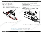
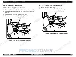
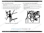
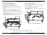
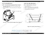
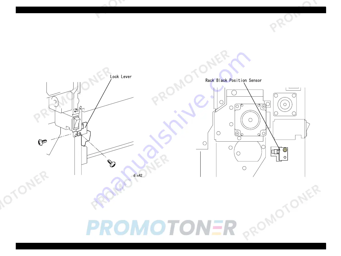
4.2.19.3 Rack Lock Lever Removal
1. Remove the Rear Controller Cover. (See “Rear Controller Cover Removal”
on page -145.)
2. Remove the Rear Cover. (See “Rear Cover Removal” on page -146.)
3. Remove the Controller Box. (See "Controller Box Removal" on page 150.)
4. Remove the Left Cover. (See “Left Cover Removal” on page -144.)
5. Remove 2 screws securing the Rack Lock Lever to the main frame.
Figure 4-45. Rack Lock Lever Removal
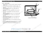
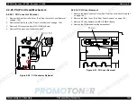
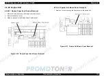
4.2.19.4 Rack Black Position Sensor Removal
1. Remove the Rear Controller Cover. (See “Rear Controller Cover Removal”
on page -145.)
2. Remove the Rear Cover. (See “Rear Cover Removal” on page -146.)
3. Remove the HV1 (High Voltage Board). (See “HV1 (High Voltage Board)
Removal” on page -152.)
4. Remove 1 screw securing the Rack Black Position Sensor and 1
connector.
Figure 4-46. Rack Black Position Sensor Removal
Summary of Contents for ACULASER COLOR 1000
Page 1: ...EPSON ACULASERCOLOR2000 ACULASERCOLOR1000 A4 Color Laser Printer SEPG00004 SERVICE MANUAL ...
Page 12: ...C H A P T E R 1 PRODUCTDESCRIPTIONS ...
Page 68: ...C H A P T E R 2 OPERATINGPRINCIPLES ...
Page 104: ...C H A P T E R 3 TROUBLESHOOTING ...
Page 138: ...C H A P T E R 4 DISASSEMBLYANDASSEMBLY ...
Page 182: ...C H A P T E R 5 ADJUSTMENT ...
Page 187: ...C H A P T E R 6 MAINTENANCE ...
Page 189: ...C H A P T E R 7 APPENDIX ...
Page 191: ......
Page 192: ......
Page 220: ......
Page 221: ......
Page 222: ......
Page 223: ......
Page 224: ......
Page 225: ......
Page 226: ......
Page 227: ......
Page 228: ......
Page 229: ......
Page 230: ......


