background image

Epson Artisan 

7

00


Epson Stylus Photo PX

7

00FW/


Epson Stylus Photo TX

7

00FW/


Color Inkjet Printer

SEMF08-004

SERVICE MANUAL

Confidential

Summary of Contents for Artisan 700 Series

Page 1: ...EpsonArtisan700 EpsonStylusPhotoPX700FW EpsonStylusPhotoTX700FW Color Inkjet Printer SEMF08 004 SERVICE MANUAL Confidential ...

Page 2: ...RKING ON POWER SUPPLY AND OTHER ELECTRONIC COMPONENTS 4 WHEN DISASSEMBLING OR ASSEMBLING A PRODUCT MAKE SURE TO WEAR GLOVES TO AVOID INJURIER FROM METAL PARTS WITH SHARP EDGES WARNING 1 REPAIRS ON EPSON PRODUCT SHOULD BE PERFORMED ONLY BY AN EPSON CERTIFIED REPAIR TECHNICIAN 2 MAKE CERTAIN THAT THE SOURCE VOLTAGES IS THE SAME AS THE RATED VOLTAGE LISTED ON THE SERIAL NUMBER RATING PLATE IF THE EPS...

Page 3: ...r reference Connector Summary Symbols Used in this Manual Various symbols are used throughout this manual either to provide additional information on a specific topic or to warn of possible danger present during a procedure or an action Be aware of all symbols when they are used and always read NOTE CAUTION or WARNING messages Indicates an operating or maintenance procedure practice or condition t...

Page 4: ...D 31 1 7 1 4 Relation Between Original and Copy 31 1 7 2 Memory Card Direct Print Function Photos Mode 32 1 7 2 1 Supported Paper and Print Mode 32 1 7 2 2 Supported File Type and Media Type 32 1 7 2 3 Automatic Detection of Images in Memory Card 33 1 7 2 4 Specifications for Handling Image Data 33 1 7 2 5 Memory Card Direct Print Menu 34 1 7 2 6 Makes Prints from Index Sheet Function 35 1 7 2 7 P...

Page 5: ...Button 106 4 2 2 5 Upper Housing 107 4 2 2 6 Rear Left Housing 109 4 2 2 7 Left Housing Decoration Belt L 109 4 2 2 8 Stacker Assy 110 4 2 2 9 Rear ASF Paper Guide Cover 111 4 2 2 10 Rear Right FAX Housing 112 4 2 2 11 Right Housing Card Cover 113 4 2 2 12 Cassette Unit 114 4 2 2 13 Paper Guide Top Assy 115 4 2 3 Removing the Circuit Board 115 4 2 3 1 Panel Unit 115 4 2 3 2 Main Board Grounding Pl...

Page 6: ...3 2 3 Card Slot Assy Artisan 700 PX700W TX700W 199 4 3 3 Disassembling the Scanner Unit Artisan 700 PX700W TX700W 200 4 3 3 1 Document Cover 200 4 3 3 2 Scanner Upper Housing Artisan 700 PX700W TX700W 201 4 4 Routing FFC cables 202 Chapter 5 ADJUSTMENT 5 1 Adjustment Items and Overview 210 5 1 1 Servicing Adjustment Item List 210 5 1 2 Required Adjustments 216 5 2 Adjustment Using Adjustment Progr...

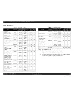
Page 7: ...Confidential C H A P T E R 1 PRODUCTDESCRIPTION ...

Page 8: ...nal storage device Backup copy of a memory card can be made on an external media Offers camera direct print PictBridge Network Available for printing scanning and memory card access via wired wireless network Wireless Mounting the optional Bluetooth unit offers wireless communication with an external device Features unique to Epson Artisan 800 Epson Stylus Photo PX800FW TX800FW FAX Sending receivi...

Page 9: ... EPSON Remote command Input buffer size 64 Kbytes Paper feed method Friction feed using the ASF Auto Sheet Feeder Paper path Front feed front out Paper feed rates T B D ms at 25 4mm feed PF interval Programmable in 0 01764 mm 1 1440 inch steps Table 1 2 Product No of Ink Cartridges Color EAI Latin CISMEA Asia Euro Black T0981 S T0811N S T0821N 2S T0791 S T0801 2S Cyan T0982 S T0992 2S T0812N S T08...

Page 10: ...I Glossy Photo Paper others Premium Photo Paper Glossy EAI Premium Glossy Photo Paper others Premium Photo Paper Semi Gloss EAI Premium Semigloss Photo Paper other Fine 720x360 MC1 2 240cps ON ON OK Photo 2 720x720 1 0 pass MC1 2 240cps ON ON OK Photo 2 720x720 2 0 pass MC2 2 280cps ON ON OK Super Photo SMGA 5760x1440 MC1 5 200cps ON ON OK PremiumPresentation Paper Matte EAI Matte Paper Heavyweigh...

Page 11: ...Photo Paper others Premium Photo Paper Glossy EAI Premium Glossy Photo Paper others Premium Photo Paper Semi Gloss EAI Premium Semigloss Photo Paper other Fine 720x360 MC1 2 240cps ON ON OK Photo 2 720x720 1 0 pass MC1 2 240cps ON ON OK Photo 2 720x720 2 0 pass MC2 2 280cps ON ON OK Super Photo SMGA 5760x1440 MC1 5 200cps ON ON OK PremiumPresentation Paper Matte EAI Matte Paper Heavyweight others ...

Page 12: ... 5 5 x8 5 Y Y A6 105 x 148 mm 4 2 x5 8 Y Y Y Y User Defined 89 x 127 215 9 x 1117 6 mm 3 5 x5 8 5 x44 Y Y Y Y 5 Premium Inkjet Plain Paper A4 210 x 297 mm 8 3 x11 7 0 11 80 g m2 21 lb Y Y Y Y Y Premium Bright White Paper EAI Letter 215 9 x 279 4 mm 8 5 x11 0 11 90 g m2 24 lb Y Y Y Bright White Inkjet Paper Euro Asia A4 210 x 297 mm 8 3 x11 7 0 13 92 5 g m2 25 lb Y Y Y Y Y Ultra Premium Glossy Phot...

Page 13: ...oto Paper Luster Letter 215 9 x 279 4 mm 8 5 x11 0 27 250 g m2 66 lb Y Y Y Double sided Matte Paper Letter 215 9 x 279 4 mm 8 5 x11 0 22 185 g m2 49 lb Y Y Y Y A4 210 x 297 mm 8 3 x11 7 Y Y Y Y Y Y Y Photo Quality Inkjet Paper Letter 215 9 x 279 4 mm 8 5 x11 0 13 102 g m2 27 lb Y Y A4 210 x 297 mm 8 3 x11 7 Y Y Y Y Envelopes 10 104 8 x 241 3 mm 4 125 x9 5 75 100 g m2 20 27 lb Y Y Y Y DL 110 x 220 ...

Page 14: ...nt are margins that bleed off the edges of paper Figure 1 1 Printing Area C A U T I O N Make sure the paper is not wrinkled fluffed torn or folded The curve of paper must be 5 mm or below When printing on an envelope be sure the flap is folded neatly Do not use the adhesive envelopes Do not use double envelopes and cellophane window envelopes Tray 1 Tray 2 CDR Tray Paper feed tray position Table 1...

Page 15: ...nary document Home position The rear left corner Photoelectric device CIS Light source LED Maximum document sizes A4 or US letter Scanning range 8 5 x 11 7 216 mm x 297 mm Maximum resolution Main scan 4 800 dpi 1 200 dpi Sub scan 4 800 dpi 600 dpi Main scan 2 400 dpi Sub scan 4 800 dpi Maximum effective pixels 40 800 x 56 160 pixels 20 400 x 28 080 pixels Pixel depth 16 bit per pixel input and 1 b...

Page 16: ...Noise Epson Artisan 800 Epson Stylus Photo PX800FW TX800FW PC Printing 1 T B D dB Scanning 2 T B D dB Epson Artisan 700 Epson Stylus Photo PX700W TX700W PC Printing 1 35 dB Scanning 2 27 dB Note 1 Premium Glossy Photo Paper Highest quality 2 default setting Table 1 11 Primary Power Specifications Item Epson Artisan 800 Epson Stylus Photo PX800FW TX800FW Epson Artisan 700 Epson Stylus Photo PX700W ...

Page 17: ...thead Six billions shots per nozzle or five years whichever comes first Scanner carriage 30 000 cycles of carriage movement Total ADF feeding 10 000 pages Table 1 12 Environmental Conditions Condition Temperature 1 Humidity 1 2 Shock Vibration Operating 10 to 35 C 50 to 95 F 20 to 80 1G 1 msec or less 0 15G 10 to 55Hz Storage unpacked 20 to 40 C 3 4 F to 104 F 5 to 85 2G 2 msec or less 0 50G 10 to...

Page 18: ...for the Wired LAN connection The communication mode can be selected from auto setting or fixed setting Note 10Base T 100Base TX Ethernet is supported MDI MDI X is selected automatically Table 1 13 USB Interface Specifications Item USB Device port USB Host port Compatible standards Universal Serial Bus Specifications Revision 2 0 Universal Serial Bus Device Class Definition for Printing Devices Ver...

Page 19: ...ll Duplex 100BASE TX Full Duplex 100BASE TX Half Duplex Auto Setting AUTO 100BASE TX Half Duplex 10BASE T Full Duplex 10BASE T Full Duplex 10BASE T Half Duplex Auto Setting AUTO 10BASE T Half Duplex Table 1 18 Wireless LAN Item Content Applied Standard 2 4GHz spectrum band wireless network standards Conforms to IEEE802 11b IEEE802 11g Wireless Operation Mode IEEE802 11b DS SS Half Duplex IEEE802 1...

Page 20: ...move the card using tweezers Table 1 21 List of Supported Memory Card Priority Slot Compatible memory card Standard Max capacity Remarks 1 Memory Stick Memory Stick PRO Memory Stick MemoryStick Standard Format Specification Ver 1 43 00 compatible 128MB Includes versions with memory select function MagicGate Memory Stick 128MB Copy protection function is not supported MagicGate Memory Stick Duo An ...

Page 21: ...l 1 6 1 Operation Buttons LEDs Figure 1 5 Control Panel Epson Artisan 700 Epson Stylus Photo PX700W TX700W LCD Mode button Display Crop button Cross Key and OK button Menu button Start button Stop Clear Settings button button Auto Correct button Unlock button Print Tray button Power button Power LED Back button Blue status light ...

Page 22: ... defaults and displays the Top screen Returns to the previous screen during printing maintaining the current settings Back Cancels the previous operation Cross Key OK Selects a menu item or a setting value Accepts the changed settings Menu Goes to the menu screen for each mode Auto Correct Changes the Auto Correct ON OFF Print Tray Ejects retracts the CDR Tray Mode Changes modes in the following o...

Page 23: ...f Brightness Standard Contrast Standard Sharpness Standard Saturation Standard Print Proof SheetPaper Paper Size 4 x 6 10 x 15 Paper Type Prem Glossy infomation File name Table 1 25 Timing of Saving or Initializing Control Panel Settings Mode Print Setting Default Value Print Photo Photo Layout Sheet Layout 2 up Paper Size 4 x 6 10 x 15 Paper Type Prem Glossy Layout Method Automatic layout Photo L...

Page 24: ... x 6 Paper Type Prem Glossy Layout Borderless Print 1 Frame 12 up Print N Frame Quality Standard Quality Expansion Standard Fit Frame On Bidirectional On Movie Enhance On Fix Photo Fix Photo On Filter Off Brightness Standard Contrast Standard Sharpness Standard Saturation Standard Table 1 25 Timing of Saving or Initializing Control Panel Settings Mode Print Setting Default Value Table 1 26 Support...

Page 25: ...ting 1 Selects either On or Off Print setting Paper type Selects paper type from the options shown in Table 1 26 Paper size Selects paper size from the options shown in Table 1 26 Quality Selects print quality from the options shown in Table 1 26 Zoom Selects zoom type from the 13 types below Actual Sets any zoom with key 25 to 400 after selecting Actual Auto Fit Page Legal Letter Letter 4x6 4x6 L...

Page 26: ...hrome copy 18 3 18 5 cpm Color copy 17 7 18 0 cpm Table 1 30 Copy Speed Copy Conditions Copy Speed per copy per five copies Default Monochrome copy 3 1 cpm 3 0 cpm Color copy 1 1 cpm 1 7 cpm Best Monochrome copy 0 8 cpm 0 4 cpm Color copy 0 8 cpm 0 4 cpm Original Document A Scan bed B Scan area 1 10 Scanning Range p 20 C Original face down OTM Top margin out of scan range 1 10 Scanning Range p 20 ...

Page 27: ...d 720x720 MC2 2 ON ON Best SMGA 5760x1440 MC1 5 ON ON Ultra Glossy letter 1 A4 5 x 7 8 x 10 1 4 x 6 16 9wide Standard 3 720x720 MC1 2 ON ON Standard 720x720 MC2 2 ON ON Best SMGA 5760x1440 MC1 5 ON ON Photo Sticker1 2 A6 Standard 720x720 MC2 2 ON ON Photo Stickers 2 100 x 148mm 3 9 x 5 8 Standard 720x720 MC2 2 ON ON CD DVD CD DVD Best SMGA 5760x1440 MC1 5 ON ON Table 1 32 Supported File System Typ...

Page 28: ...amera definition files can be selected to be printed even when the total number of images has exceeded 9 990 Up to 999 camera defined image files can be specified Maximum number of copies 99 copies for each image Up to 999 sheets in total Valid date and time 01 01 1980 00 00 00 to 12 31 2099 23 59 59 Thumbnail image data Supports DCF Ver 1 0 or 2 0 compatible data Exif format 160x120 pixels Thumbn...

Page 29: ...ndex sheet Print on CD DVD Prints the specified image as a CD DVD label Test printing on an A4 paper is also available Photo Greeting Card Prints a template with specified images and combines the images and hand writing on it by scanning it then prints it on the 4 x 6 paper Photo Layout Sheet Prints the images in a memory card with various layout Refer to Figure 1 9 for layout Print Index Sheet Pr...

Page 30: ...nt Index Sheet Setting Select According to the setting made by the control panel Table 1 36 Rules on Reading Markings Item Mark Description Remarks Left edge one each Reference position for reading markings An error occurs if these markings cannot be read due to ink stain or any other cause Right edge one each Reference position for reading markings Block code 36 pcs Sheet information memory card ...

Page 31: ...y for Euro Asia 3 Prints in a layout of the CD DVD label Note Supported paper sizes differ depending on the types of paper Table 1 38 Supported Paper Type and Layout 1 Paper Type UI notation Corresponding Layout Borderless With Border Upper 1 2 Lower 1 2 2 up 4 up 8 up 20 up 16 up 2 Index 20 up Index 30 up Index 80 up CD With Border CD 4 up CD variety Jewel Case Upper 1 2 Jewel Case Index Picture ...

Page 32: ...eeting Card 1 Photo Greeting Card 1up Borderless with Border Photo Greeting Card Upper 1 2 Photo Greeting Card Lower 1 2 Reprint Restore Photos Borderless With Border Note Print Play movie and Print Photos Print 1 frame Borderless Play movie and Print Photos Print 1 frame With Border Play movie and Print Photos Print 1 frame Upper 1 2 Play movie and Print Photos Print 1 frame Lower 1 2 Play movie ...

Page 33: ...wn in the figure below indicate the photo frame numbers used for the print layout Horizontally oriented images are printed as shown by the numbers Vertically oriented images which has more pixels vertically than horizontally the vertical photo data is allocated instead and the number shown in the figure below is then rotated 90 degrees before being printed In Index printing mode the numbers are pr...

Page 34: ... 9 10 11 12 1 2 3 4 5 6 7 8 9 10 11 12 13 14 15 16 17 18 19 20 13 14 15 16 17 18 19 20 21 22 23 24 2 3 4 5 6 7 8 9 10 11 12 13 14 15 16 17 18 19 20 5 6 1 21 22 23 24 26 27 28 29 30 25 2 3 4 5 6 7 8 1 10 11 12 13 14 15 16 9 18 19 20 21 22 23 24 17 26 27 28 29 30 31 32 25 34 35 36 37 38 39 40 33 42 43 44 45 46 47 48 41 50 51 52 53 54 55 56 49 58 59 60 61 62 63 64 57 66 67 68 69 70 71 72 65 74 75 76 ...

Page 35: ...not been made on the DSC the corresponding settings made on the printer are applied 1 7 3 4 Operations when a DSC is connected C H E C K P O I N T Before connecting the DSC check that the printer is in the following status No print job from a computer is processed or performed Direct print from a memory card is not processed or performed Stand alone copy using the scanner function is not operating...

Page 36: ...tern Head Cleaning Runs a printhead cleaning The cleaning cannot be made when low ink level is detected In such case an ink low error is displayed instead of running the cleaning Head Alignment Adjustment to improve the bi directional print quality Head alignment icon and the instructions for the adjustment are displayed on the LCD Automatic Head Maintenance Selects On Off of the auto head cleanin...

Page 37: ...settings made here For details refer to 1 7 3 Camera Direct Print Function PictBridge p 39 Select Location Selects a folder when printing from an external device other than DSC Restore Default Settings Restores the default settings for FAX and Network Individual initialization of network or other settings is available for Epson Artisan 700 Epson Stylus Photo PX700W TX700W Table 1 42 Menu List for ...

Page 38: ... IP Address Manual IP Address XXX XXX XXX XXX Subnet Mask XXX XXX XXX XXX Default Gateway XXX XXX XXX XXX APIPA Disable Acquisition way of DNS ADDR Disable Primary DNS Address XXX XXX XXX XXX Secondary DNS Address XXX XXX XXX XXX Proxy Use Disable Proxy Address 1 2 3 4 5 6 7 8 9 0 1 2 3 4 5 6 7 8 9 0 1 2 3 4 5 Proxy Port NONE Universal Plug and Play Disable Device Name 1 Internet Connect State Ena...

Page 39: ...lain paper Resolution Standard 360 x 360 dpi Dot size MC2 1 Bi directional Available Microweave N A Borderless printing N A Automatic reduction On Off Backup fax reception and reprint Available List Type Last transaction off send error every send Fax log last 30 transactions Speed dial list Power fail report Protocol trace Font size 12pt Language Depends on destination Size mismatch Print 2 Footer...

Page 40: ...irect dial Total digits 64 Max Redial Busy Fixed to two times No answer Buffer Last one number Redial interval Fixed to one minute Redial attempts Fixed to two times Dial mode Pulse PBX N A Dial prefix N A On hook dialing N A Function Specification Auto answer On Off with answer mode button Ring to answer 1 9 times DRD All single double triple double triple TAM IF Available Easy receive N A Answer...

Page 41: ... function 1 7 6 2 Backup Data You can save data as a back up from the file in the memory card to the file in the externally connected CDR drive etc or delete all the files in the memory card 1 7 6 3 Print Ruled Papers You can print ruled lines on A4 plain paper for use of a sheet of notebook or a letter by operating according to the instructions displayed on the LCD Ten types of ruled lines are av...

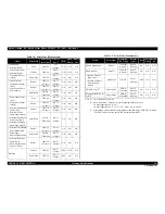
Page 42: ...Confidential C H A P T E R 2 OPERATINGPRINCIPLES ...

Page 43: ... below Figure 2 2 Nozzle Layout PF Encoder PW Sensor CR Encoder PF Roller EJ Roller Carriage Assy Printhead Cartridge Box Unit Ink System Decompression Motor 1 CDR Tray Sensor 3 Duplex Unit Sensor 1 PF Motor 2 Photo Tray Sensor CR Motor PE Sensor Carriage Shaft EJ Cover Open Plunger 2 3 CDR Tray Intermediate Roller Cover Open Sensor EJ Frame Assy LD Roller Pick up Roller Color Bk C M Y Lc Lm 6 col...

Page 44: ...Name Motors Sensors name Printhead Carriage mechanism CR Motor A CR Encoder 1 PW Sensor 2 Paper feeding mechanism PF Motor B PF Encoder 3 PE Sensor 4 CDR Tray Sensor 5 EJ Cover Open Plunger 6 Photo Tray Sensor 7 Ink Supply mechanism Decompression Motor C Duplex Printing mechanism Duplex Unit Sensor 8 C H E C K P O I N T See 3 2 1 Motor and Sensor Troubleshooting p 55 for the each motor and sensor ...

Page 45: ...e Scanner Carriage Unit Open close detection mechanism Cover Open Sensor 9 Drive section of Scanner Carriage mechanism Scanner Motor D Scanner CR Encoder 10 Table 2 3 Motors Sensors ADF Name Motors Sensors name Paper feeding mechanism ADF Motor E ADF DOC Sensor 11 ADF PE Sensor 12 C H E C K P O I N T See 3 2 1 Motor and Sensor Troubleshooting p 55 for the each motor and sensor specification 9 D 10...

Page 46: ...s 1 Pos 2 Pos 3 Pos 4 PG PG Typ PG PG PG measurement mm 1 2 1 7 2 35 5 8 Position name Home position Normal position PG large position PG max position Description Printing EPSON brand paper Plain paper printing Avoiding friction of PG Envelope printing Avoiding friction of PG Typ CD DVD Not printing Capping Wiping Ready position after initialization AID Capping Capping Capping EJ release Rotating ...

Page 47: ...2 Operator initialization Initialization when resetting the USB software and the following are performed a Clears input data buffer b Clears print buffer c Sets default values 3 Software initialization The ESC command also initialize the printer When printer is initialized the following actions are performed a Clears print buffer b Sets default values 4 IEEE 1284 4 rs command initialization The pr...

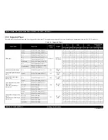
Page 48: ...Confidential C H A P T E R 3 TROUBLESHOOTING ...

Page 49: ...paper used must conform to the specification There is no error in handling of the printer Check the inside of the printer and remove foreign matters if any such as paper clips staples bits of paper paper dust or toner Clean the inside of the printer and the rubber rolls W A R N I N G Be careful to avoid electric shocks when checking the electrical circuit boards while the power is turned on Touchi...

Page 50: ... Table 3 2 Sensor check point Sensor name Check point Signal level Switch mode PE Sensor Transmissive photo interrupter Main Board Pin1 Pin2 of CN9 Less than 0 4 V No paper More than 2 4 V Detects the paper Scanner Cover Open Sensor 1 GMR sensor Main Board Pin1 Pin2 of CN10 Less than 0 4 V Scanner Open More than 2 4 V Scanner Closed Scanner Cover Open Sensor 2 GMR sensor Main Board Pin2 Pin4 of CN...

Page 51: ...ion Maintenance request waste ink over flow The printer s ink pads are at the end of their service life Please contact Epson support The waste ink counter exceeds to capacity Table 3 5 p64 Paper jam error Paper jam Open the scanner unit Remove the jammed paper close the scanner unit then press the Start button Paper remained in the paper path after paper ejection Table 3 6 p64 Double feed error Mu...

Page 52: ...intenance then press the CD tray button A medium on the CD DVD tray was detected during cleaning or the like Table 3 13 p69 ADF paper jam error Paper jam in the automatic document feeder Remove the jammed paper Paper jam occurred in the ADF Unit Table 3 14 p69 Duplex Unit related error Duplex Unit cannot be detected Paper jam occurred in the Duplex Unit 3 5Troubleshooting Duplex Unit Problems p 78...

Page 53: ...17 2 Is the CR Motor cable damaged 2 Replace the CR Motor with a new one 4 2 4 15 CR Motor p 152 3 Does the CR Motor operate normally 3 Replace the CR Motor with a new one The Carriage Unit hits against the right side of the Main Frame CR Encoder 1 Is the CR Encoder damaged 1 Replace the CR Encoder with a new one 4 2 4 16 Carriage Unit p 154 2 Is the FFC correctly connected to the connector on the...

Page 54: ... Timing Belt correctly 4 2 4 16 Carriage Unit p 154 2 Is the CR Timing Belt correctly installed to the Pinion Gear of the CR Motor 2 Install CR Timing Belt correctly CR Timing Belt Driven Pulley Assy 1 Is tension of the CR Timing Belt appropriate 1 Reassemble the CR Timing Belt and check the tension of the CR Timing Belt again If the tension is still not appropriate replace the Printer Mechanism 4...

Page 55: ...he contamination is severe replace the printer mechanism with a new one 2 Is the PF Scale damaged 2 Replace the printer mechanism with a new one The PF Motor makes abnormal noise during operation Slipping of PF Timing Belt PF Timing Belt PF Tensioner 1 Is the PF Timing Belt damaged 1 Replace the printer mechanism with a new one 4 2 4 14 PF Motor p 150 5 3 3 PF Timing Belt Tension Adjustment p 241 ...

Page 56: ... Board Grounding Plate M B p 117 2 Is the FFC connecting the SUB Board to CN7 on the Main Board damaged 2 Replace the FFC with a new one 4 2 3 5 Card Slot Assy p 123 4 3 2 3 Card Slot Assy Artisan 700 PX700W TX700W p 199 3 Is SUB Board damaged 3 Replace the Card Slot Assy with a new one At power on During CDR printing EJ Frame Assy does not move EJ Frame Assy 1 Is EJ Frame Assy correctly installed...

Page 57: ...cified amount of grease 6 1 3 Lubrication p 249 The error occurs when PF Motor is still operating after CDR Tray was retracted CDR Tray Sensor 1 Is the CDR Tray Sensor cable properly connected to CN14 connector on the Main Board 1 Connect the CDR Tray Sensor cable to CN14 on the Main Board 4 2 3 2 Main Board Grounding Plate M B p 117 2 Is the CDR Tray Sensor cable damaged 2 Replace the printer mec...

Page 58: ... one 4 2 3 2 Main Board Grounding Plate M B p 117 1 Check if the CR Stopper is blocking the printer operation because it has fallen into the mechanism 1 Remove the CR Stopper 4 1 3 Work Completion Check p 95 4 2 2 5 Upper Housing p 107 Table 3 4 Check point for Fatal error according to each phenomenon Printer Mechanism Occurrence Timing Symptoms Failed Part Part Name Check Point Remedy Reference C...

Page 59: ... Connect the Scanner CR Encoder FFC correctly to CN49 connector on the Main Board 4 2 5 4 Scanner CR Encoder Board p 172 2 Is the Scanner CR Encoder FFC damaged 2 Replace the Scanner CR Encoder FFC with a new one Scanner Carriage FFC 1 Is the Scanner Carriage FFC properly connected to CN41 connector on the Main Board 1 Connect the Scanner Carriage FFC correctly to CN41 connector on the Main Board ...

Page 60: ... 4 Does the flap of the Lower ASF Paper Guide Assy come off 4 Install the flap of the Lower ASF Paper Guide correctly LD Roller 1 Is LD Roller shaft correctly installed 1 Install the LD Roller shaft correctly 4 2 4 9 LD Roller p 142 2 Is the surface of LD Roller contaminated with micro pearl paper dust or greasy dirt 2 Clean the LD Roller Paper Guide Top Assy 1 Is the Paper Guide Top Assy correctl...

Page 61: ...ut Error according to each phenomenon Occurrence Timing Symptoms Failed Part Part Name Check Point Remedy Reference Any time The LD Roller rotates normally but paper is not fed LD Roller 1 Is the surface of LD Roller contaminated with micro pearl paper dust or greasy dirt 1 Clean the LD Roller 4 2 4 9 LD Roller p 142 The intermediate roller rotates normally but paper is not fed Intermediate roller...

Page 62: ...FC correctly 4 2 4 4 CSIC Assy p 132 CSIC Assy 1 Is the CSIC terminal damaged 1 Replace the CSIC Assy with a new one 4 2 4 4 CSIC Assy p 132 2 Is the CR contact module damaged 2 Replace the CSIC Assy with a new one Table 3 10 Check point for the Scanner Open Error according to each phenomenon Occurrence Timing Symptoms Failed Part Part Name Check Point Remedy Reference Any time The Printer Cover i...

Page 63: ...e printer mechanism with a new one 3 Is Photo Tray Sensor damaged 3 Replace the printer mechanism with a new one Table 3 12 Check point for the CD size Error according to each phenomenon Occurrence Timing Symptoms Failed Part Part Name Check Point Remedy Reference Any time The error occurs even the 12cm CD DVD is on the CDR Tray PW Sensor 1 Is the PW Sensor free from ink stain or paper dust 1 Clea...

Page 64: ...ray 4 2 4 8 CDR Tray Assy p 140 2 Is CDR Tray correctly installed 2 Install CDR Tray correctly Table 3 14 Check point for the ADF Paper Jam Error according to each phenomenon Occurrence Timing Symptoms Failed Part Part Name Check Point Remedy Reference At power on The error displays on the LCD after initialization at power on ADF Cover Assy 1 Is the ADF Cover Assy closed 1 Close the ADF Cover Assy...

Page 65: ...aper Feed Problems Problem Possible Cause Check point Remedy Paper is not fed Paper Guide Top Assy installation error Is the Paper Guide Top Assy correctly installed Install the Paper Guide Top Assy correctly See 4 2 2 13 Paper Guide Top Assy p 115 Contamination or wear of the Pick up Roller intermediate rollers LD Roller Is the surface of each Rollers contaminated with micro pearl paper dust or g...

Page 66: ...here is no connection error found See 4 2 3 2 Main Board Grounding Plate M B p 117 Table 3 18 Troubleshooting Carriage Movement Problems Problem Possible Cause Check point Remedy The movements of Carriage Unit during printing is abnormal Something is obstructing the Carriage movements Is there any obstructions on the Carriage path Remove the obstructions See 4 2 4 16 Carriage Unit p 154 Does the C...

Page 67: ...d swab Ink cartridge failure Replace the ink cartridges with new ones and run a nozzle check Replace the Ink cartridges with new ones Poor connection of the Head FFC Check the FFC using a tester Does the result show abnormality Replace the Head FFC with a new one See 4 2 4 1 Printhead p 124 4 2 4 16 Carriage Unit p 154 Printhead failure Run a cleaning several times and then run a nozzle check If t...

Page 68: ...rame and apply G 71 grease as specified See 6 1 3 Lubrication p 249 Improper platen gap Is the platen gap setting correct Carry out the PG adjustment See 5 3 1 PG Adjustment p 235 Damage of gears Are the gears of the PF and ASF mechanisms free from damage or deformation Replace the faulty part with a new one Due to contamination on the Printhead surface ink droplets are fired diagonally Run a clea...

Page 69: ...r Does the result show abnormality Replace the Head FFC with a new one See 4 2 4 1 Printhead p 124 4 2 4 16 Carriage Unit p 154 Printhead failure Run a cleaning and make a test print Repeat it several times If the cleaning does not solve the problem replace the Printhead with a new one See 4 2 4 1 Printhead p 124 Ink leak or clogging Is ink leakage observed on the Printhead Cartridge Box Unit Inst...

Page 70: ...e if any damage is observed See 4 2 4 6 Ink System p 135 Disconnection of the Ink Tube from the cap Is the tube properly connected to the lower part of the Cap Connect the tubes correctly See 4 2 4 6 Ink System p 135 Cap movement failure Is the compression spring of the cap section properly engaged Replace the Ink System with a new one See 4 2 4 6 Ink System p 135 The tube between the Waste Ink Tr...

Page 71: ...Cable properly connected to CN501 connector on the Main Board Connect the cable correctly The fuse is blown Is the fuse F1 on the Power Supply Board blown Replace the Power Supply Board Abnormal output of the Power Supply Board Is a normal voltage being output from the Power Supply Board Replace the Main Board when the output voltage is normal Replace the Power Supply Unit when the output voltage ...

Page 72: ...Card is recognized Replace the Memory Card with a new one Poor connection Are the memory card or the slot free from foreign materials Remove the foreign material and clean the contact points Is the slot pin cracked or deformed Replace the Card Board Firmware error Update the firmware Memory card can not be ejected Is the memory card inserted without the memory card adapter Turn the power off and r...

Page 73: ...lace the printer mechanism with a new one Check if the duplex unit sensor is damaged If so replace the printer mechanism with a new one The duplex unit open error occurs when duplex printing is started after recovering from a duplex unit paper jam error 1 The duplex unit is not installed correctly Install the duplex unit correctly The duplex printing is resumed from the next page Cancel the duplex...

Page 74: ... Wireless LAN and Wired LAN can not be used at the same time 2 Check if the combination for the HUB and router etc and Link Speed of the Printer is proper Correct the Link Speed setting properly 3 Check if 10Base T Repeater HUB is used Try other HUBs Switching HUB etc Table 3 29 Troubles in Installing a Software Symptom Check Point Remedy Can not connect to internet thru LAN is displayed 1 In Wire...

Page 75: ... and the printer to a LAN port such as a hub or router using a LAN cable 3 Check the status of network settings connection by printing the network status sheet Correctly set the network connection again if the network connection is not made 4 Check if the link lamp on the Access Point or hub connected to the printer is lighting or flashing Try using another port Replace the LAN cable Configure Wir...

Page 76: ...sensitive microprocessors and circuitry use static discharge equipment such as anti static wrist straps when accessing internal components Never touch the ink or wasted ink with bare hands If ink comes into contact with your skin wash it off with soap and water immediately If you have a skin irritation consult a doctor immediately W A R N I N G When powering this product high voltage current may b...

Page 77: ...003963 Nippers O Ink Supply Tube screwing tool 1508164 PG adjustment tool 1508165 Leak Check jig Air Release jig Carriage Stopper jig Table 4 2 Work Completion Check Classification Item Check Point Status Printer Unit Self test Is the operation normal OK NG ON line Test Is the printing successful OK NG Printhead Nozzle check pattern print Is ink discharged normally from all the nozzles OK NG Carri...

Page 78: ...y action normal OK NG Adjustment Specified Adjustment Are all the adjustment done correctly OK NG Lubrication Specified Lubrication Are all the lubrication made at the specified points OK NG Is the amount of lubrication correct OK NG Function ROM Version Version OK NG Packing Ink Cartridge Are the ink cartridges installed correctly OK NG Waste Ink pad Are the waste ink pads adequate to absorb OK N...

Page 79: ...arts name Reference page Artisan 800 PX800FW TX800FW Artisan 700 PX700W TX700W ADF Unit ADF mechanism No ADF mechanism Artisan 800 PX800FW TX800FW 4 2 2 1 ADF Unit Artisan 800 PX800FW TX800FW only p 102 Scanner Unit The Document Cover and Housing are different depend on the ADF mechanism or not Artisan 800 PX800FW TX800FW 4 2 6 Disassembly of the ADF Unit Artisan 800 PX800FW TX800FW only p 174 4 2...

Page 80: ...800 PX800FW TX800FW 4 2 2 Removing the Housing p 102 Artisan 700 PX700W TX700W 4 3 1 Removing the Housing p 185 Main Board The specification of the Main Board is different as well as the positions of the connectors Artisan 800 PX800FW TX800FW 4 2 3 Removing the Circuit Board p 115 Artisan 700 PX700W TX700W 4 3 2 Removing the Circuit Board Artisan 700 PX700W TX700W p 194 FAX FAX No FAX Table 4 3 Pr...

Page 81: ... Front Paper Guide Waste Ink Pad p166 4 2 2 12 Cassette Unit p114 4 2 4 21 Lower Paper Guide Waste Ink Pad Assy p165 4 2 2 7 Left Housing Decoration Belt L p109 4 2 3 3 Power Supply Unit p121 4 2 4 7 Lower ASF Paper Guide Assy p138 4 2 2 9 Rear ASF Paper Guide Cover p111 4 2 4 9 LD Roller p142 4 2 4 20 Waste Ink Tray Assy p163 4 2 2 10 Rear Right FAX Housing p112 4 2 2 11 Right Housing Card Cover ...

Page 82: ...er Guide L R PE Sensor p161 4 2 4 12 Front Frame p147 4 2 4 14 PF Motor p150 4 2 4 15 CR Motor p152 4 2 4 13 EJ Frame Assy EJ Release Frame Assy R EJ Release Frame Assy L p147 Disassembling the Scanner Unit START Artisan 700 PX700W TX700W 4 2 5 1 Scanner Upper Housing Artisan 800 PX800FW TX800FW p167 4 2 5 2 Scanner Motor Unit p168 4 2 5 3 Scanner Carriage Unit p169 4 3 3 1 Document Cover p200 4 3...

Page 83: ...00W p 188 4 2 2 6 Rear Left Housing p 109 4 3 1 4 Rear Left Housing Artisan 700 PX700W TX700W p 190 4 2 2 7 Left Housing Decoration Belt L p 109 4 3 1 5 Left Housing Decoration Belt L Artisan 700 PX700W TX700W p 191 4 2 2 10 Rear Right FAX Housing p 112 4 3 1 6 Rear Right Housing Artisan 700 PX700W TX700W p 192 4 2 2 11 Right Housing Card Cover p 113 4 3 1 7 Right Housing Card Cover Artisan 700 PX...

Page 84: ...Scanner FFCs x3 together with the Ferrite Cores x2 from the Main Board See Fig 4 6 3 Pull out the terminal of the Grounding Wire from the fixing rib of the frame Figure 4 6 Removing the Scanner Unit 1 The disassembly reassembly procedures of Artisan 700 PX700W TX700W differ from those of Artisan 800 PX800FW TX800FW See 4 3 1 1 Scanner Unit Artisan 700 PX700W TX700W p185 for the procedures Groundin...

Page 85: ...1Kgfcm Scanner Unit 1 2 When installing the Scanner Unit follow the procedure below 1 Align and insert the dowel of the Scanner Unit to the positioning hole of the printer Left inside 2 Align and insert the rib of the Scanner Unit to the groove of the Hinge Figure 4 9 Installing the Scanner Unit 1 3 While aligning the screw holes with the Scanner Unit open secure them temporarily with the screw x1...

Page 86: ...s no gap between the Scanner Unit and the printer Figure 4 11 Installing the Scanner Unit Make sure to insert the terminal of the Grounding wire to the fixing rib of the Frame See Fig 4 6 For the routing of the FFCs see 4 4 Routing FFC cables p202 When installing the Cable Cover secure it with a new Harness Cover Clamp See Fig 4 3 A D J U S T M E N T R E Q U I R E D After removing replacing the Sc...

Page 87: ...Release the hooks x2 and ribs x2 of the Upper Left Housing and remove the Upper Left Housing Figure 4 13 Removing the Upper Left Housing 3 Remove the Panel Lock Button Figure 4 14 Removing the Panel Lock Button C H E C K P O I N T The disassembly reassembly procedures of Artisan 700 PX700W TX700W differ from those of Artisan 800 PX800FW TX800FW See 4 3 1 2 Upper Left Housing Artisan 700 PX700W TX7...

Page 88: ...lease the hooks x2 and ribs x3 of the Front Harness Cover with the flathead screwdriver and remove the Front Harness Cover from the Upper Housing Figure 4 16 Removing the Upper Housing 1 C H E C K P O I N T The disassembly reassembly procedures of Artisan 700 PX700W TX700W differ from those of Artisan 800 PX800FW TX800FW See 4 3 1 3 Upper Housing Artisan 700 PX700W TX700W p188 for the procedures C...

Page 89: ... See 4 2 3 1 Panel Unit p115 1 2 3 4 5 7 8 6 Panel Unit 9 C B S 3x6 8 1Kgfcm C B S 3x8 black 8 1Kgfcm C B P 3x10 6 1Kgfcm C B A 3x8 black 6 1Kgfcm C B P 3x10 black 6 1Kgfcm Rib Hook Upper Housing Left Housing Right Housing Panel FFC Main Board Upper Housing Insert the ribs x4 of the Upper Housing to the inside of the Housing L R when installing the Upper Housing See Fig 4 17 Tighten the screws in ...

Page 90: ...using Removal procedure 1 Remove the screw x1 that secures the Decoration Belt and remove the Decoration Belt from the Left Housing See Fig 4 20 2 Remove the screw x1 that secures the Left Housing Figure 4 20 Removing the Left Housing Decoration Belt L 1 C H E C K P O I N T The disassembly reassembly procedures of Artisan 700 PX700W TX700W See 4 3 1 4 Rear Left Housing Artisan 700 PX700W TX700W p1...

Page 91: ...center of the Stacker Assy and release the dowels x4 from the grooves of the Base Frame and remove the Stacker Assy Figure 4 23 Removing the Stacker Assy C A U T I O N So as to make description easier the printer in the photographs is placed vertically in the following steps Be careful about ink spilling if the printer is tilted in practical operation Align and insert the rib in the front inside o...

Page 92: ...hook x1 and remove the Rear ASF Paper Guide Cover Figure 4 25 Removing the Rear ASF Paper Guide Cover Make sure that the antistatic seals x2 on the bottom of the Stacker Assy are correctly attached Figure 4 24 Attachment position of the antistatic seal Antistatic seals 0 2 mm 0 1 mm 0 1 mm Insert the ribs x2 of the Rear ASF Paper Guide Cover to the inside of the Housing and secure it with the hook...

Page 93: ...e Rear Right FAX Housing by lifting it in the direction of the arrow See Fig 4 26 Fig 4 27 Figure 4 27 Removing the Rear Right FAX Housing 2 C H E C K P O I N T The disassembly reassembly procedures of Artisan 700 PX700W TX700W See 4 3 1 6 Rear Right Housing Artisan 700 PX700W TX700W p192 for the procedures C B A 3x8 black 6 1Kgfcm C B S 3x6 black 8 1Kgfcm C B P 3x10 6 1Kgfcm Hook A Rear Right FAX...

Page 94: ...e Fig 4 28 and hooks x3 on the bottom of the Right Housing and remove the Right Housing Figure 4 29 Removing the Right Housing Card Cover 2 3 Release the hooks x2 from the back of the Right Housing and remove the Card Cover Figure 4 30 Removing the Right Housing Card Cover 3 C H E C K P O I N T The disassembly reassembly procedures of Artisan 700 PX700W TX700W See 4 3 1 7 Right Housing Card Cover ...

Page 95: ...ng to the dowel of the Base Frame See Fig 4 28 Attach the Card Cover after installing the Right Housing to the Printer When attaching the Card Cover insert the ribs x2 of the Card Cover to the inside of the Right Housing and secure it with the hooks x2 Figure 4 31 Attaching the Card Cover Hook Rib Right Housing Card Cover When replacing the cork A B wipe the attaching position with ethanol and att...

Page 96: ... Upper Left Housing Removal procedure 1 Remove the Grounding Wire See 4 2 2 5 Upper Housing Step1 p107 2 Remove the Panel Spring x1 See Fig 4 35 3 Remove the screws x2 that secure the Ratchet Holder Assy Figure 4 35 Removing the Ratchet Holder Assy 1 Align and insert the dowels x2 of the Paper Guide Top Assy to the grooves of the Housing and secure it with the hooks x2 See Fig 4 34 Paper Guide Top...

Page 97: ...isconnect the Panel FFC from the connector of the Panel Unit See Fig 4 38 9 Remove the screw x1 that secures the Panel Unit and remove the Panel Unit from the Upper Housing Figure 4 38 Removing the Panel Unit 2 Step 4 Rib A Panel Unit Step 5 Ratchet Holder Assy Front Panel Unit Cover Panel Unit Upper Panel Cover Hook of the Upper Panel Cover Hook of the Front Panel Unit Cover Align and insert the ...

Page 98: ... because the data of the number of printed CDRs can not be transferred When this happens replace the CDR Tray Assy with a new one together with the Main Board See 4 2 4 8 CDR Tray Assy p140 Table 4 4 Connectors on the Main Board CN No Cable FFC Connector Color Number of pins Artisan 800 PX800FW TX800FW Artisan 700 PX700W TX700W CN1 Head FFC 14 CN2 Head FFC 14 CN3 Head FFC 14 CN4 Head FFC 14 CN5 CS...

Page 99: ...d Artisan 800 PX800FW TX800FW only See Fig 4 41 2 Remove the screws x7 that secure the Upper Shield Plate M B and remove the Upper Shield Plate M B Figure 4 41 Removing the Main Board 1 3 Remove the screws x3 that secure the Main Board and remove the Main Board from the Lower Shield Plate M B Figure 4 42 Removing the Main Board 2 C B P 3x10 6 1Kgfcm Step 3 Holder IC Shield Plate Ferrite Core Holde...

Page 100: ...fcm I F B FFC Dowel groove Align the positioning holes x2 of the Main Board with the dowels x2 of the Upper Shield Plate M B See Fig 4 42 When installing the Main Board tighten the screws in the order shown in Fig 4 42 Align the dowels x2 of the Lower Shield Plate M B with the grooves x2 of the Upper Shield Plate M B See Fig 4 41 Align the positioning holes x2 of the FAX Board with the dowels of t...

Page 101: ...unding Plate M B Attach this part to the FAX Board side I F B FFC Main Board Hole Rib Grounding Plate M B When attaching the CR Encoder FFC follow the procedure below 1 Put the CR Encoder FFC through the ferrite core 2 Connect the CR Encoder FFC to the connector CN6 on the Main Board 3 Insert the rib of the Ferrite Core Holder B to the hole of the Main Board and secure it with the screw x1 Figure ...

Page 102: ...e Base Frame Figure 4 49 Removing the Power Supply Unit Double sided tape Rib Connector Power Supply Unit cable PF Encoder FFC C B P 3x8 6 1Kgfcm C B S 3x6 8 1Kgfcm Power Supply Unit Route the Power Supply Unit Cable through the groove of the Base Frame then install the Power Supply Unit to the Base Frame Figure 4 50 Installing the Power Supply Unit Install the Power Supply Unit inside the ribs x2...

Page 103: ...sing Right Housing Removal procedure 1 Remove the screws x2 that secure the Wireless LAN Board and remove the Wireless LAN Board from the hooks x2 of the Base Frame Figure 4 51 Removing the Wireless LAN Board 1 2 Disconnect the Wireless LAN cable from the connector and remove the Wireless LAN Board Figure 4 52 Removing the Wireless LAN Board 2 Wireless LAN Board C B P 3x8 6 1Kgfcm Hook When instal...

Page 104: ...9 for the procedures The Card Slot Assy includes the SUB Board and the STG Board W A R N I N G When powering this product high voltage current may be applied on the SUB Board To prevent ELECTRIC SHOCK do not touch the SUB Board section when the power is ON If the shock should happen the flowing current is very tiny about a few hundreds μA therefore it will not do any harm on the human body C B P 3...

Page 105: ...ad C A U T I O N The procedure including checks adjustments required before after removing or replacing the Printhead varies according to the target part to replace Make sure to follow the figure below when operating Figure 4 56 Related work for removing installing the Printhead 5 4 1 I S Decompress p244 Disassembling an exterior etc See Disassembling Flowchart 1 p99 Removing Printhead p125 Removi...

Page 106: ...ock and placing the Carriage stopper jig 4 Remove the screws x4 that secure the Printhead and the Ink Supply Tube Assy and detach the Printhead from the Carriage Unit Figure 4 58 Removing the Printhead 1 5 Disconnect the Head FFC x2 from the Printhead Figure 4 59 Removing the Printhead 2 Spur Gear Carriage Lock is under the Carriage Unit Carriage Lock 0 digit side Carriage Unit Carriage stopper ji...

Page 107: ...2 5Kgfcm Printhead C A U T I O N When assembling the Printhead make sure to use the Ink Supply Tube screwing tool following the procedure in this section in order to avoid spilling ink from the joint of the Ink Supply Tube Assy and the Printhead Figure 4 61 Ink Supply Tube screwing tool C H E C K P O I N T When installing the Printhead confirm the CR Seal is not folded or out of position then inst...

Page 108: ... align the screw to the hole and turn it to the left slightly to engage the threaded parts of the screw and the hole correctly then tighten it Make sure to follow the specified tightening torque When securing the Printhead make sure to observe strictly the following Otherwise the Printhead may be secured at an angle which may adversely affect the print quality C B P 2x10 2 5Kgfcm Printhead 1 2 3 2...

Page 109: ... the Ink Supply Tube screwing tool and remove the tool gently while holding the Ink Supply Tube Assy Figure 4 67 Assembling the Printhead 4 8 Tighten the screws x2 in order shown in Fig 4 68 while holding the thickness gauge and secure the Ink Supply Tube Assy to the Printhead Figure 4 68 Assembling the Printhead 5 C H E C K P O I N T If the joint of the Printhead and the Ink Supply Tube Assy is n...

Page 110: ...nk penetrating into the Decompression Tube located inside the Ink Supply Tube Assy If such ink penetration is observed make sure to replace the Ink Supply IC Holder Assy p133 together with the Printhead A D J U S T M E N T R E Q U I R E D After removing replacing the Printhead make the specified adjustments See Chapter 5 ADJUSTMENT When disconnecting the joint of the Printhead and the Ink Tube in ...

Page 111: ...f the Cartridge Box Unit See Fig 4 71 2 Release the decompression tube from the groove on the Base Frame Figure 4 71 Removing the Decompression Pump Unit Attach the CR Scale to the hook on the left of the printer with the chipped part upward See Fig 4 70 Make sure to put the CR Scale through the slit of the CR Encoder Sensor See Fig 4 69 When installing the Torsion Spring 16 43 follow the procedur...

Page 112: ...B P 3x8 6 1Kgfcm When routing the Decompression Pump Motor cable make sure to secure it with the dowels x6 and the hook on top of the Decompression Pump Unit as shown in Fig 4 72 When routing the decompression tube confirm no clipped part or fold on the tube See Fig 4 71 Fig 4 73 Figure 4 73 Installing the Decompression Pump Unit Put the decompression tube through the groove on the Base Frame sect...

Page 113: ...r Guide Top Assy Upper Housing Removal procedure 1 Disconnect the CSIC FFC from the CSIC connector Figure 4 74 Removing the CSIC Assy 1 2 Release the hooks x2 on the rear of the Cartridge Box and remove the CSIC Assy upward Figure 4 75 Removing the CSIC Assy 2 C H E C K P O I N T In the case of Artisan 700 PX700W TX700W removing the Right Rear Housing p192 and the Right Housing p193 earlier will m...

Page 114: ... from the Cartridge Box Unit Figure 4 77 Removing the IC Guide 3 Disconnect the decompression tube from the socket on the Cartridge Box Unit See Fig 4 71 4 Remove the screws x7 that secure the Cartridge Box Unit Figure 4 78 Removing the Cartridge Box Unit C H E C K P O I N T The Ink Supply IC Holder Assy consists of the Ink Supply Tube Assy and the Cartridge Box Unit See Fig 4 55 If the replacemen...

Page 115: ...se ink leakage therefore make sure to replace the Ink Supply IC Holder Assy with a new one Cartridge Box Unit Ink Supply Tube Assy FFC Clamp Tube FFC Holder Section A Make sure to insert the decompression tube into the socket on the Cartridge Box Unit to the full to its base See Fig 4 71 Make sure to align the positioning hole x1 on the Cartridge Box Unit with the dowel x1 of the Base Frame when r...

Page 116: ...Fig 4 81 Figure 4 81 Installing the Clamp Tube When installing the Ink Supply IC Holder Assy make sure to remove slack around the section B by moving the Carriage Unit between the 0 digit side and the 80 digit side a few times Figure 4 82 Installing the Ink Supply IC Holder Assy For routing the FFCs see 4 4 Routing FFC cables p202 A D J U S T M E N T R E Q U I R E D After removing replacing the In...

Page 117: ...about ink spilling from the Waste Ink Tube Do not damage the Rubber Seal or the Head Cleaner on the cap with frames or other parts See Fig 4 87 Ink System Waste Ink Tube AID cable Connector on SUB Board Groove on Base Frame Bottom side Install the Ink System as follows 1 When the Carriage Lock sticks out rotate the Combination Gear in the direction of the arrow to lower the Carriage Lock Figure 4 ...

Page 118: ...wel Positioning hole Transmission Holder Assy Position A 5 Push the switch lever in the direction of the arrow and turn the spur gear see Fig 4 86 then align the Transmission Arm to the position A Ink System operation point shown in Fig 4 87 6 Connect the AID cable to the connector on the SUB Board and route the cable through the groove on the Base Frame See Fig 4 84 7 Visually check the cap secti...

Page 119: ...over Removal procedure 1 Release the hooks x2 and remove the Spur Gear A Figure 4 88 Removing the Lower ASF Paper Guide Assy 1 2 Remove the screws x3 that secure the Lower ASF Paper Guide Assy See Fig 4 89 3 Remove the Lower ASF Paper Guide Assy while avoiding hitting the shaft of the Intermediate Roller A to the groove A on the Base Frame Figure 4 89 Removing the Lower ASF Paper Guide Assy 2 Left...

Page 120: ...ving the Lower ASF Paper Guide Assy 4 C B P 3x8 6 1Kgfcm Roller fixing plate Lower ASF Paper Guide Assy Intermediate Roller A Rear side Lower ASF Paper Guide Assy Intermediate Roller A Rear side Paper feed defect will occur if the flap of the Lower ASF Paper Guide Assy comes off therefore take care in the following points to make sure that the flap is surely attached when installing the Lower ASF ...

Page 121: ... Spur Gear C See Fig 4 89 When installing the Lower ASF Paper Guide Assy the tip of the flap is inserted between the CDR Tray Assy and the Upper Paper Guide Take care not to damage the flap by getting contact with such parts then See Fig 4 93 Make sure to attach the Intermediate Roller A into the bearing on the Base Frame See Fig 4 89 Attach the rear side of the Lower ASF Paper Guide Assy so as to...

Page 122: ...nto the groove on the CDR Guide See Fig 4 95 Place the left arm over the right arm before installation See Fig 4 95 If an arm comes off place it to the CDR Tray at an angle as shown in Fig 4 96 and insert the hole of the arm into the hook on the tray then rotate it in the direction of the arrow to engage the arm to the tray Figure 4 96 Reassembling the CDR Tray Assy When installing the Spur Gear B...

Page 123: ...ler 1 2 Release the hooks x2 on the Spur Gear and remove it from the shaft of the Intermediate Roller Figure 4 98 Removing the LD Roller 2 3 Lift the Intermediate Roller on the Power Supply Unit side and remove the roller while pulling the other side of the shaft from the hole on the Base Frame Figure 4 99 Removing the LD Roller 3 4 Remove the screws x2 that secure the Rear Paper Guide Assy and re...

Page 124: ... Shaft Figure 4 102 Removing the Pick up Roller 1 C A U T I O N Never touch or damage the surface of the LD Roller as doing so can adversely affect print quality Make sure to align the dowels x4 on the Base Frame with the positioning holes x4 when reassembling the Rear Paper Guide Assy See Fig 4 100 A D J U S T M E N T R E Q U I R E D When replacing the LD Roller make sure to carry out the specifi...

Page 125: ...SF Paper Guide Cover Lower ASF Paper Guide Assy CDR Tray Assy Main Board CSIC Assy Wireless LAN Board Cartridge Box Unit Ink Supply Tube Assy Card Slot Assy Decompression Pump Unit Waste Ink Tray Assy Removal procedure C A U T I O N Be careful not to touch or damage the Pick up Roller so can adversely affect print quality A D J U S T M E N T R E Q U I R E D When replacing the Pick up Roller make s...

Page 126: ...connector See Fig 4 105 Figure 4 105 Removing the Main Frame 1 4 Remove the Grounding Plate B See Fig 4 106 5 Remove the screws x7 that secure the Main Frame and remove the Main Frame from the Base Frame Figure 4 106 Removing the Main Frame 2 Dowel of the Base Frame PE Sensor Cable Front Frame Plunger Cable Hook Connector of the PF Motor Cable Hole of the Base Frame C A U T I O N When removing the...

Page 127: ...Base Frame See Fig 4 106 Tighten the screws in the order shown in Fig 4 106 For routing the cables see 4 4 Routing FFC cables p202 Grounding Plate A Grounding Plate B Hook and hole When installing the Main Frame be careful not to let it hit the Base Frame If the EJ Release Frame Assy L hits the Base Frame see Fig 4 113 the gear will come off which may cause the operation defect Figure 4 108 Instal...

Page 128: ...nd remove the EJ Release Frame Assy R Figure 4 110 Removing the EJ Release Frame Assy R C H E C K P O I N T The Main Frame becomes unstable once it is removed from the Base Frame Be careful not to deform the frame during performing the following procedures Refer to 4 2 4 11 Main Frame p144 for the Parts Components need to be removed before removing the Main Frame Align the positioning holes x2 of ...

Page 129: ...ut and remove the EJ Frame Assy from the EJ Frame Shaft Figure 4 112 Removing the EJ Frame Assy 2 5 Remove the screw x1 that secures the EJ Release Frame Assy L and remove the EJ Release Frame Assy L with the EJ Frame Shaft Figure 4 113 Removing the EJ Release Frame Assy L Spur Gear EJ Frame Assy Grounding spring Grounding spring EJ Frame Shaft EJ Frame Assy EJ Release Frame Assy L EJ Frame Shaft ...

Page 130: ...J Frame Assy Protrusions and holes EJ Frame Assy After installing the EJ Release Frame Assy L follow the procedure below to check the movement of the EJ Release Trigger 1 Rotate the EJ Roller counterclockwise as seen from the left side and make the EJ Release Trigger stay on the CR Guide Plate 2 Lift the CR Guide Plate slightly and push the EJ Release Trigger to the 80 digit side 3 Make sure to en...

Page 131: ...e Tensioner together with the Driven Pulley Figure 4 119 Removing the PF Motor 2 C H E C K P O I N T The Main Frame becomes unstable once it is removed from the Base Frame Be careful not to deform the frame during performing the following procedures Refer to 4 2 4 11 Main Frame p144 for the Parts Components need to be removed before removing the Main Frame C A U T I O N Be careful not to touch the...

Page 132: ...ion Gear PF Motor Hole When installing the PF Motor keep the groove of the PF Motor upward Figure 4 122 Installing the PF Motor When installing the Spacer align the positioning holes x2 of the Spacer with the dowels x2 of the Holder Make sure there is no gap between upper left end of the Spacer and the Tensioner If there is a gap turn the Spacer around or over so that another letter 2 4 or 1 comes...

Page 133: ... the dowels x2 of the Main Frame See Fig 4 120 Insert the Compression Spring to the dowel of the Tensioner and attach it to the protrusion of the Tension Holder reinforcing plate See Fig 4 119 A D J U S T M E N T R E Q U I R E D After removing replacing the PF Motor make the specified adjustments See Chapter 5 ADJUSTMENT After replacing the PF Motor be sure to perform the required lubrication See ...

Page 134: ...Remove the screws x4 that secure the CR Motor and remove the CR Motor Assy Figure 4 126 Removing the CR Motor 2 7 Remove the screws x2 that secure the CR Motor and remove the CR Motor from the CR Motor Holder Figure 4 127 Removing the CR Motor 3 PG Lever R Right side Parallelism Bushing C B S 3x6 Secure it after PG Adjustment Dowel shaft hole Parallelism Bushing The screw that secures the CR Motor...

Page 135: ...t of the Spur Gear Align the point B of the Spur Gear B with the point C of the Spur Gear C to make the phases of both gears match Figure 4 128 Aligning the Spur Gear A D J U S T M E N T R E Q U I R E D After removing replacing the CR Motor make the specified adjustments See Chapter 5 ADJUSTMENT After replacing the CR Motor be sure to perform the required lubrication See Chapter 6 MAINTENANCE Spur...

Page 136: ...the Frame Sheet from the Main Frame 8 Remove the E ring and remove the PG Lever R See Fig 4 132 9 Remove the Torsion Spring R Figure 4 132 Removing the Carriage Unit 1 10 Remove the securing ring that secure the PG Cam R and remove the PG Cam R See Fig 4 135 11 Remove the Flat Washer and the Spring Washer Figure 4 133 Removing the Carriage Unit 2 C A U T I O N Be careful not to lose the Driven Pul...

Page 137: ...iage Unit at the cutout of the CR Guide Plate and remove the point A on the rear of the Carriage Unit from the CR Guide Plate Figure 4 136 Removing the Carriage Unit 5 16 Move the Carriage Unit to the center Figure 4 137 Removing the Carriage Unit 6 C A U T I O N Be careful not to touch the PF Scale with bare hands Be careful not to damage or contaminate the PF Scale Left side E ring PG Lever L Ri...

Page 138: ... attach it to the ribs x2 of the Main Frame See Fig 4 135 When installing the Frame Sheet attach it with double sided tape while aligning it with the edge of the Main Frame See Fig 4 132 Carriage Unit Carriage Shaft Point B When replacing the CR Timing Belt insert the CR Timing Belt to the Timing Belt Holder and install it to the Carriage Unit as shown in Fig 4 139 Figure 4 139 Installing the CR T...

Page 139: ...er Assy C H E C K P O I N T The Main Frame becomes unstable once it is removed from the Base Frame Be careful not to deform the frame during performing the following procedures Refer to 4 2 4 11 Main Frame p144 for the Parts Components need to be removed before removing the Main Frame Switch Lever Transmission Arm C B P 3x8 6 1Kgfcm Transmission Holder Assy PE Sensor Cable Make sure that all gears...

Page 140: ...omes unstable once it is removed from the Base Frame Be careful not to deform the frame during performing the following procedures Refer to 4 2 4 11 Main Frame p144 for the Parts Components need to be removed before removing the Main Frame C A U T I O N Deformed antistatic cloth attached on the Rear Frame will cause ink mist adhering to the print surface therefore make sure not to touch the antist...

Page 141: ...e ribs x2 of the Rear Frame with the positioning holes x2 of the Main Frame See Fig 4 145 Take care of the following points when installing the Torsion Spring A B and C Attach the Torsion Spring A x4 to the ribs of the Main Frame Attach the Torsion Spring B x2 and C x2 to the ribs of the Rear Frame Align and attach the straight legs of the springs to the groove of the Upper Paper Guide L R Attach ...

Page 142: ...emoving the Upper Paper Guide R PE Sensor 2 Disconnect the PE Sensor cable from the connector See Fig 4 149 3 Remove the screw x1 that secures the PE Sensor and remove the PE Sensor avoiding the damage to the Upper Paper Guide sheet Figure 4 149 Removing the PE Sensor C H E C K P O I N T The Main Frame becomes unstable once it is removed from the Base Frame Be careful not to deform the frame durin...

Page 143: ...nsor with the dowel of the Paper Guide Front Assy See Fig 4 149 When installing the PE Sensor insert the sensor with the Upper Paper Guide sheet in between See Fig 4 149 Fig 4 151 Figure 4 151 Installing the PE Sensor The roller of the Upper Paper Guide R in the figure below only is installed in the opposite direction therefore make sure to install it properly when the roller comes off Figure 4 15...

Page 144: ...eck if the point A of the Sub Transmission Cam Holder locks the protrusion of the Transmission Arm and the arm moves to the middle 2 By sliding the switch lever further to the 0 digit side check if the lock is released and the Sub Transmission Cam Holder returns to the regular position when letting go of the change lever Figure 4 153 Installing the Sub Transmission Cam Holder A D J U S T M E N T R...

Page 145: ...6 Figure 4 156 Attaching the Waste Ink Tube Waste Ink Tube Tube Stopper Waste Ink Tray Assy Waste Ink Cover Hook 47mm Waste Ink Tube Tube Stopper The Waste Ink Tray Assy includes below waste ink pads Figure 4 157 Installing the Waste Ink Tray Assy Location ASP Name Qty A POROUS PAD INK EJ FRONT LOWER 1 B POROUS PAD INK EJ LOWER 1 C POROUS PAD INK EJ LEFT 2 D POROUS PAD INK EJ FRONT 2 2 E POROUS PA...

Page 146: ...with the hook x1 and screw x1 See Fig 4 154 Fig 4 155 Fig 4 158 Figure 4 158 Installing the Waste Ink Tray Assy A D J U S T M E N T R E Q U I R E D After removing replacing the Waste Ink Tray Assy make the specified adjustments See Chapter 5 ADJUSTMENT Rib hole Waste Ink Tray Assy C A U T I O N Be careful about ink spilling if the printer is tilted in practical operation Align the ribs x3 of the L...

Page 147: ... Unit Lower Paper Guide Waste Ink Pad Assy Removal procedure 1 Remove the Front Paper Guide Waste Ink Pad with tweezers Figure 4 160 Removing the Front Paper Guide Waste Ink Pad Install the Front Paper Guide Waste Ink Pad without any gap See Fig 4 160 Insert the Front Paper Guide Waste Ink Pad till the legs x8 of Front Paper Guide Waste Ink Pad come out from the Front Paper Guide Figure 4 161 Inst...

Page 148: ...W Refer to procedures on the flowchart Flowchart 4 2 Disassembling Flowchart 2 p100 for Artisan 700 PX700W TX700W C A U T I O N It is recommended to remove the Scanner Upper Housing in a clean room or on a clean bench to keep away from dust and dirt Be careful not to damage the document glass on the Scanner Upper Housing Bottom side C B P 3x10 5 1kgfcm Scanner Upper Housing When installing the Upp...

Page 149: ...e provided in Reassembly etc C A U T I O N Be sure of the following Be careful not to touch the Scanner CR Scale with bare hands Be careful not to damage the Scanner CR Scale Scanner Motor Unit Scanner Motor cable CN2 Scanner CR Encoder Board C B P 3x8 5 1kgfcm Positioning hole dowel Groove Screw it with the Grounding Wire Grounding Wire When installing the Scanner Motor Unit be sure of the follow...

Page 150: ...Route the Grounding Wire between the ribs x5 and frame Groove Grounding Wire C H E C K P O I N T Some of the parts of Artisan 800 PX800FW TX800FW differ from those of Artisan 700 PX700W TX700W Unless otherwise specified this section describes the procedures for Artisan 800 PX800FW TX800FW The differences that may affect the disassembly reassembly procedures of Artisan 700 PX700W TX700W will be pro...

Page 151: ... 3 Turn the Combination Gear 12 1 11 3 in the direction of the arrow and move the Scanner Carriage Unit to the center 4 Remove the Driven Pulley and Combination Gear12 1 11 3 from the Scanner Lower Housing and remove the Scanner Timing Belt Figure 4 169 Removing the Scanner Carriage Unit 2 Ferrite Core Scanner Cable Cover Scanner Carriage FFC Rib Scanner Carriage FFC Rear side Artisan 800 PX800FW ...

Page 152: ...secured with double sided tape x2 When attaching the Scanner Cable Cover route the FFC and Grounding Wire as shown below Figure 4 171 Attaching the Scanner Cable Cover Scanner Carriage Unit Scanner Carriage FFC Scanner CR Encoder FFC Cover Open Sensor FFC Scanner Carriage FFC Grounding Wire A B C C A C A B B Rib Groove Rear side Artisan 800 PX800FW TX800FW Artisan 700 PX700W TX700W Rear side A D J...

Page 153: ...ncoder FFC from the connector CN1 on the Scanner CR Encoder Board 3 Loosen the screw that secures the Scanner CR Encoder Board to the Scanner Lower Housing and remove Scanner CR Encoder Board from the Scanner Lower Housing Figure 4 172 Removing the Scanner CR Encoder Board Scanner CR Encoder Board CN1 Scanner CR Encoder FFC Rib C B S 3x8 5 1kgfcm When routing the Scanner CR Encoder FFC of Artisan ...

Page 154: ...74 Removing the Cover Open Sensor 1 2 Disconnect the Cover Open Sensor FFC from the connector of the Cover Open Sensor and remove the Cover Open Sensor from the Scanner Lower Housing Figure 4 175 Removing the Cover Open Sensor 2 C H E C K P O I N T Sensor Cover Artisan 800 PX800FW TX800FW Hook Sensor Cover Artisan 700 PX700W TX700W When attaching the Cover Open Sensor insert it into the space insi...

Page 155: ... the ADF Hinges and remove the ADF Hinges from the ADF Base Assy Figure 4 178 Removing the ADF Hinge When routing the Cover Open Sensor FFC route it as shown below and in Fig 4 171 Figure 4 177 Routing the Cover Open Sensor FFC Rib Double sided tape Artisan 800 PX800FW TX800FW Artisan 700 PX700W TX700W Cover Open Sensor FFC Cover Open Sensor FFC Put FFC through ferrite core and secure it with doub...

Page 156: ... 2 Release the guide pins x2 that secure the ADF Cover Assy and remove the ADF Cover Assy Figure 4 179 Removing the ADF Cover Assy 3 Release the hooks x2 and the dowel x1 that secure the ADF Cover L and remove the ADF Cover L Figure 4 180 Removing the ADF Cover L ADF Cover Assy Guide Pin When installing the ADF Cover L align the ribs x5 of the ADF Cover L with the grooves x5 of the ADF Base Assy F...

Page 157: ...2 Removing the ADF LD Frame Assy 4 2 6 4 ADF Right Cover ADF Rear Cover Parts Components need to be removed in advance Scanner Unit ADF Unit ADF Cover Assy Removal procedure 1 Release the hooks x3 that secure the ADF Right Cover and remove the ADF Right Cover from the ADF Base Assy Figure 4 183 Removing the ADF Right Cover When installing the ADF LD Frame Assy align the dowels x4 of the ADF Cover ...

Page 158: ...ng the ADF Rear Cover ADF Rear Cover C B P 2 5x6 black 6 1kgfcm Hook C B P 2 5x6 6 1kgfcm ADF Base Assy ADF Document Support Cover When installing the ADF Right Cover align the positioning holes x2 with the dowels x2 of the ADF Right Cover and the ADF Base Assy and also align the ribs x6 shown in Fig 4 183 Figure 4 185 Installing the ADF Right Cover When installing the ADF Rear Cover align the rib...

Page 159: ...er and remove the ADF Cover Stacker from the ADF Base Assy Figure 4 187 Removing the ADF Cover Stacker 2 Release the dowels x2 that secure the ADF Document Support Cover and remove the ADF Document Support Cover from the ADF Base Assy Figure 4 188 Removing the ADF Document Support Cover Dowel ADF Cover Stacker ADF Base Assy Protrusions of the ADF Document Support Cover When installing the ADF Cove...

Page 160: ...ent Support Assy Parts Components need to be removed in advance Scanner Unit ADF Unit ADF Cover Assy ADF Right Cover ADF Rear Cover ADF Cover Stacker ADF Document Support Cover ADF Front Cover Removal procedure 1 Release the hooks x2 that secure the ADF Document Support Assy 2 Release the dowels x2 that secure the ADF Document Support Assy and remove the ADF Document Support Assy from the ADF Base...

Page 161: ...it 3 Release the dowel x1 of the ADF Base and the dowels x2 of the ADF Frame Unit then remove the ADF Frame Unit from the ADF Base Assy Figure 4 192 Removing the ADF Frame Unit 2 ADF Frame Unit Groove ADF Base Assy Acetate tapes Cable of the ADF Unit ADF Cable Cover When installing the ADF Frame Unit align the positioning holes x3 of the ADF Frame Unit and ADF Base Assy with the dowels x3 as shown...

Page 162: ... and the Grounding Wire 2 Release the hooks x4 of the ADF Cable Cover and open the ADF Cable Cover then release the ADF Motor cable the ADF Sensor cable and the Grounding Wire Figure 4 193 Releasing the cables 3 Remove the screws x2 that secure the ADF Motor Unit Figure 4 195 Removing the ADF Motor Unit 1 ADF Cable Cover Hook Acetate tapes x2 Acetate tape ADF Sensor cable Grounding Wire ADF Motor ...

Page 163: ...afts holes ADF Frame Unit ADF Motor Unit C B P 3x8 6 1kgfcm Grounding Wire Be careful of the following when installing the ADF Motor Unit Route the ADF Motor cable the ADF Sensor cable and the Grounding Wire as shown below Figure 4 197 Routing the cables Attach the torsion spring from under the ADF EJ Roller Figure 4 198 Attaching the torsion spring Insert the shaft of the ADF Motor Unit to the ho...

Page 164: ...Spur Gear 6 4 securing ring and the ADF EJ Rear Bush from the ADF PF Roller Figure 4 200 Removing the ADF PF Roller 1 2 Release the hooks x2 and remove the ADF EJ Front Bush from the ADF Frame Unit Figure 4 201 Removing the ADF PF Roller 2 When placing the cables on the ADF Cable Cover route them as shown below Figure 4 199 Routing the cables in the ADF Cable Cover ADF Cable Cover ADF Sensor cable...

Page 165: ...ADF PF Roller from the ADF Frame Unit in the direction of the arrow Figure 4 202 Removing the ADF PF Roller 3 When installing the ADF PF Roller attach the leg of the torsion spring on the ADF PF Roller as shown in Fig 4 202 A D J U S T M E N T R E Q U I R E D After replacing or removing the ADF PF Roller be sure to perform the required lubrication See Chapter 6 MAINTENANCE ADF PF Roller E ring Tor...

Page 166: ...the Ferrite core x1 from the Main Board 5 Pull out the terminal of the Grounding Wire from the Frame Figure 4 204 Removing the Scanner Unit 1 6 Remove the screw x1 that secures the Scanner Unit Figure 4 205 Removing the Scanner Unit 2 C H E C K P O I N T The disassembly reassembly procedures for Artisan 800 PX800FW TX800FW differ from those of Artisan 700 PX700W TX700W see 4 2 2 2 Scanner Unit p10...

Page 167: ...the procedure below 1 Align and insert the dowel of the Scanner Unit to the positioning hole of the printer Left inside 2 Align and insert the rib of the Scanner Unit to the groove of the Hinge Figure 4 207 Installing the Scanner Unit 1 3 While aligning and inserting the rib of the Scanner Unit to the groove of the Hinge secure them with the screw x1 temporarily with the screw holes aligned as sho...

Page 168: ... screw x1 after making sure that there is no gap between the Scanner Unit and the printer Figure 4 208 Installing the Scanner Unit 2 Make sure to insert the terminal of the Grounding wire to the fixing rib of the frame See Fig 4 204 For the routing the FFCs see 4 4 Routing FFC cables p202 When installing the Cable Cover secure it with a new Harness Cover Clamp See Fig 4 203 A D J U S T M E N T R E...

Page 169: ... While pushing the Panel Lock Button slide the Panel Upper Cover in the direction of the arrow to release the hook x8 of the Panel Upper Cover and remove the Panel Upper Cover Figure 4 211 Removing the Upper Housing 1 C H E C K P O I N T The disassembly reassembly procedures for Artisan 800 PX800FW TX800FW differ from those of Artisan 700 PX700W TX700W see 4 2 2 5 Upper Housing p107 for the proced...

Page 170: ...o the Panel Unit See Fig 4 214 8 Disconnect the Panel FFC from the connector on the Panel Unit and remove the Upper Housing together with the Panel Unit Figure 4 214 Removing the Upper Housing 4 9 Remove the Panel Unit from the Upper Housing See 4 3 2 1 Panel Unit Artisan 700 PX700W TX700W p194 1 2 3 4 5 7 8 C B S 3x6 8 1Kgfcm C B S 3x8 black 8 1Kgfcm C B P 3x10 6 1Kgfcm C B A 3x6 black 6 1Kgfcm 6...

Page 171: ...ft Housing and remove the Rear Left Housing Figure 4 216 Removing the Rear Left Housing A D J U S T M E N T R E Q U I R E D After removing replacing the Upper Housing make the specified adjustments See Chapter 5 ADJUSTMENT C H E C K P O I N T The disassembly reassembly procedures for Artisan 800 PX800FW TX800FW differ from those of Artisan 700 PX700W TX700W see 4 2 2 6 Rear Left Housing p109 for t...

Page 172: ...he Left Housing Decoration Belt L 2 C H E C K P O I N T The disassembly reassembly procedures for Artisan 800 PX800FW TX800FW differ from those of Artisan 700 PX700W TX700W see 4 2 2 7 Left Housing Decoration Belt L p109 for the procedures C B A 3x6 black 6 1Kgfcm C B P 3x10 6 1Kgfcm Decoration Belt Left Housing C A U T I O N So as to make description easier the printer in the photographs is place...

Page 173: ... lifting it in the direction of the arrow See Fig 4 220 Figure 4 221 Removing the Rear Right Housing 2 l C H E C K P O I N T The disassembly reassembly procedures for Artisan 800 PX800FW TX800FW differ from those of Artisan 700 PX700W TX700W see 4 2 2 10 Rear Right FAX Housing p112 for the procedures C B A 3x10 black 6 1Kgfcm C B S 3x6 black 8 1Kgfcm C B P 3x10 6 1Kgfcm Hook A Rear Right Housing W...

Page 174: ...e front side See Fig 4 222 and hooks x3 on the bottom of the Right Housing and remove the Right Housing Figure 4 223 Removing the Right Housing Card Cover 2 3 Release the hooks x2 on the back of the Right Housing and remove the Card Cover Figure 4 224 Removing the Right Housing Card Cover 3 C H E C K P O I N T The disassembly reassembly procedures for Artisan 800 PX800FW TX800FW differ from those ...

Page 175: ...ing Figure 4 226 Removing the Panel Unit 1 Align and insert the positioning hole of the Right Housing to the dowel of the Base Frame See Fig 4 222 Attach the Card Cover after installing the Right Housing to the printer When attaching the Card Cover insert the ribs x2 of the Card Cover to the inside of the Right Housing and secure it with the hooks x2 Figure 4 225 Attaching the Card Cover Hook Rib ...

Page 176: ... the Panel Unit 2 4 Lift the Panel Unit so as not to let the Right Hinge interfere with the Upper Housing and remove the shaft from the bushing on the left side of the Panel Unit and then remove the Panel Unit Figure 4 228 Removing the Panel Unit 3 Rib of the shaft Groove of the Upper Housing Bushing Panel Unit Right Hinge A D J U S T M E N T R E Q U I R E D After replacing the Panel Unit be sure ...

Page 177: ...e disassembly reassembly procedures for Artisan 800 PX800FW TX800FW differ from those of Artisan 700 PX700W TX700W see 4 2 3 2 Main Board Grounding Plate M B p117 for the procedures C A U T I O N When printing the CDR the CDR Tray feed amount is adjusted with compensation depending on the deterioration of the CDR Tray and the correction level is determined by the number of printed CDRs If the data...

Page 178: ...moving the Main Board 1 7 Remove the screws x6 that secure the Upper Shield Plate M B and remove the Upper Shield Plate M B Figure 4 233 Removing the Main Board 2 8 Remove the screws x3 that secure the Main Board and remove the Lower Shield Plate M B from the Main Board Figure 4 234 Removing the Main Board 3 Step 5 C B P 3x10 6 1Kgfcm C B S 3x6 7 1Kgfcm C B P 3x8 6 1Kgfcm Positioning hole dowel Ma...

Page 179: ...ing Plate M B See Fig 4 232 Fig 4 235 Figure 4 235 Attaching the Grounding Plate M B Hole Rib When replacing the Grounding Plate Sheet M B insert the sheet between the FFC and the Main Frame and secure it with double sided tape to the Grounding Plate M B See Fig 4 230 When attaching the Ferrite Core Holder A follow the procedure below 1 Align the dowels x2 of the Main Board Unit with the positioni...

Page 180: ...the MAC address need to be set if the EEPROM data could not be read from the old Main Board In this case attach the new Label MAC address Parts number 1489232 to the position shown in Fig 4 237 and execute 5 2 6 MAC Address Setting p223 Figure 4 237 Position for the MAC Address Label After removing replacing the Main Board make the specified adjustments See Chapter 5 ADJUSTMENT Label MAC address C...

Page 181: ...ent Cover closed and remove the Document Cover from the Scanner Upper Housing in the direction of the arrow Figure 4 240 Removing the Document Cover Connect the AID cable properly to the connector on the SUB Board See Fig 4 239 Align the grooves x2 of the Card Slot Assy with the dowels x2 of the Base Frame See Fig 4 238 When attaching the Grounding Plate install it over the Card Slot Assy and tigh...

Page 182: ...ousing Figure 4 241 Removing the Scanner Upper Housing 1 3 Release the ribs x4 on the Scanner Upper Housing and remove the Scanner Upper Housing in the direction of the arrow Figure 4 242 Removing the Scanner Upper Housing 2 C A U T I O N It is recommended to remove the Scanner Upper Housing in a clean room or on a clean bench to keep away from dust and dirt Be careful not to damage the document g...

Page 183: ...FFC cable name CN No Remarks 1 Scanner Cover Open Sensor FFC CN10 Ferrite Core x1 2 Scanner Carriage FFC CN41 Ferrite Core x1 3 Scanner CR Encoder FFC CN49 4 Grounding Wire x1 Scanner CR Encoder FFC Scanner Carriage FFC Scanner Cover Open Sensor FFC Double sided tape Grounding Wire Ferrite Core B Put the Scanner Cover Open Sensor FFC through this and secure it together with the FFC on the Main Boa...

Page 184: ... CN22 3 CR Motor Cable Ferrite Core x1 H d C B CN21 4 Decompression Pump Motor Cable H C B CN24 5 Duplex Unit Sensor Cable D A CN13 CDR Tray Sensor Cable CN14 Photo Tray Sensor Cable D A F G CN12 6 Power Supply Unit Cable Groove B Insert it between Base Frame and Decompression Pump Unit CN501 CN501 CN22 CN21 CN24 CN49 CN14 CN8 CN41 CN10 CN12 CN9 CN6 CN4 CN3 CN2 CN1 CN5 CN19 CN31 CN7 CN32 CN13 G 1 ...

Page 185: ...Fold Bottom of the Card Slot Assy SUB FFC I F FFC Mounted only in Japanese models Secure this with acetate tape on the bottom of the Card Slot Assy Acetate tape STG FFC Double sided tape Main Board Unit Ferrite Core Holder A After installation Fold STG FFC Put the FFC through the Ferrite Core Holder A after folding it back Before installation Ferrite Core Ferrite Core Holder A Double sided tape Fo...

Page 186: ...No FFC cable name CN No Remarks 1 Panel FFC CN33 Ferrite core x1 2 CR Encoder FFC CN6 3 Head FFC x4 CN1 2 3 4 4 CSIC FFC CN5 Head FFC x4 Panel FFC CSIC FFC CR Encoder FFC Put Panel FFC only through ferrite core Fold line Rib Double sided tape Spacer Attach it to Panel FFC with double sided tape and secure it with the hooks x3 CR Encoder FFC Head FFC x4 Route them through the ribs x4 and secure the...

Page 187: ...tinued to the next page No FFC cable name CN No Remarks 1 CR Encoder FFC CN6 2 Head FFC x4 CN1 2 3 4 Rib Hole Fold line Insert the CR Encoder FFC and Head FFC x4 together to the rib on the FFC Holder and the hole FFC Holder Ink Supply Tube Assy Cover Ink Supply Tube Assy with CR Encoder FFC and Head FFC x4 and secure them to the FFC Holder No FFC cable name CN No Remarks 1 Plunger cable CN19 Do no...

Page 188: ... Power Supply Unit cable Groove PF Motor cable Route through the hooks x5 and secure with the acetate tape Acetate tape Views without the CDR Power Supply Unit cable Route this through the groove on Base Frame PF Motor cable Place the relay connector to the hole on Base Frame and route the cable through the hooks x3 and the groove x1 Relay Connector Do not let this get caught Right side No FFC cab...

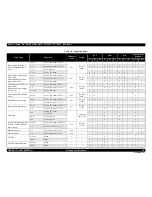
Page 189: ...Confidential C H A P T E R 5 ADJUSTMENT ...

Page 190: ...justment p235 If the position of the notch on the Parallelism Adjustment Busings have not changed only Checking the result of PG adjustment p239 is necessary Parallelism adjustment jigs two types the one for 0th column side and the one for 80th column side Fixtures for precision control Thickness Gauge 1 15mm 1 3mm Phillips screwdriver Hex wrench CR timing belt tension adjustment This adjustment i...

Page 191: ... the top left to the bottom right The Characters that can be entered as head ID are as follows ABCDEFGHJKLMNPQRSTUVWXYZ0123456789 Adjustment Program Top margin adjustment This corrects timing of printing in the paper feeding direction A top margin adjustment pattern is printed Examine the printout and carry out the adjustment so that the distance between the paper edges and the printed line falls ...

Page 192: ...esult a correction value is automatically calculated and stored into the serial flash ROM on the main board The correction value is applied when printing in the corresponding mode For more details see 5 2 10 Banding Reduction System BRS Adjustment Paper Feed Amount Profile PFP Correction p230 Adjustment Program Specified Scanner PFP base scale PFP Adjustment This adjustment is made to ensure both ...

Page 193: ...counter reaches its maximum Use this to reset the counter after replacing the Waste Ink Pad If you find the counter is close to the maximum during servicing carry out the pad replacement and the counter reset to avoid the printer returned from the user due to the maintenance error Replace the waste ink pads Waste Ink Tray Assy Lower Paper Guide Waste Ink Pad Assy and reset the counter to the defau...

Page 194: ...eplacement counter Black SS Ink replacement counter Yellow S Ink replacement counter Yellow SS Ink replacement counter Magenta S Ink replacement counter Magenta SS Ink replacement counter Cyan S Ink replacement counter Cyan SS Ink replacement counter Light Magenta S Ink replacement counter Light Magenta SS Ink replacement counter Light Cyan S Ink replacement counter Light Cyan SS Total AID counter...

Page 195: ...nt program and run it Adjustment Program I C latest error code Magenta I C latest error code Yellow I C latest error code Light Cyan I C latest error code Light Magenta Total print pass counter Total print page counter Total print page counter Duplex Total CD R print counter Total CDR tray open close counter 1st TI received time Latest fatal error code Latest fatal error code 2 Scanner fatal error...

Page 196: ...k Pad Assy and CDR Tray Assy must be replaced after replacing the main board with a new one After all required adjustments are completed use the Final check pattern print function to print all adjustment patterns for final check If you find a problem with the printout patterns carry out the adjustment again When using a new main board for replacing the Printer Mechanism the Initial setting must ha...

Page 197: ...d Assy Remove O O Replace O O O Printer Mechanism Replace O O O O O O O O O O O O O O O O O O O O O O Table 5 4 Required Adjustment List Priority 1 2 3 4 5 6 7 8 9 10 11 12 13 14 15 16 17 18 19 20 21 22 23 24 25 26 27 28 29 I S Decompress 1 3 Leak Check PG Adjustment CR timing belt tension adjustment PF timing belt tension adjustment Touch Panel Adjustment 2 EEPROM Data Copy Initial setting MAC ad...

Page 198: ...nsion adjustment Touch Panel Adjustment 2 EEPROM Data Copy Initial setting MAC address Setting PG offset value adjustment CD R Print Counter Clear Memory card check Consumables maintenance counter Ink Charge Head ID input Top margin adjustment First dot position adjustment PW adjustment Head angular adjustment AID inspection Bi D adjustment PF deterioration offset initialize PF deterioration offse...

Page 199: ...from the paper edge to the printed line Enter the value for the line that is exactly 5 mm away from the edge 5 2 2 Bi D Adjustment The pattern shown below is printed for each of the PG settings and four print modes Figure 5 2 Bi D Adjustment Pattern How to Judge Find the pattern with no gaps or overleaps of the left and right pattern and enter the value of that pattern Additional information If an...

Page 200: ...Enter the value of the point of intersection of the PW Adjustment pattern line and First Dot Position Adjustment pattern line on the left Measure the distance from the left edge of the paper to the printed line Enter the value for the line that is exactly 5 mm away from the edge Example In the left figure enter 2 since the lines intersect at 2 8 7 6 5 4 3 2 1 0 1 2 3 4 5 6 7 8 9 10 11 12 13 14 15 ...

Page 201: ...d 0 80 and enter the values of the most straight lines Additional information If the most straight lines are found on the pattern of either end reassemble the Printhead and carry out this adjustment again Microweave Pattern Figure 5 5 Head angular adjustment Pattern Printing 2 How to Judge Examine the printout patterns 2 to 2 and select the value for the group of which the gaps between the 2 color...

Page 202: ...ustment Bottom Edge Area Pattern How to Judge Input the value shown above the patterns which has no gap between the upper pattern and the lower pattern and also the both upper and lower patterns do not overlap each other Example In the above figure patterns below 4 has no gap and overlap so input 4 Additional information In case that all patterns have gap or overlap select the value for the patter...

Page 203: ... O N To avoid a conflict of MAC address on a network make sure to correctly follow the MAC address setting flowchart given on the right The MAC Address is written correctly The IP Address will be initialized also The user should be notified of the change of MAC address because of the following reasons If the user has set the printer s MAC address on a router the repaired printer with a new MAC add...

Page 204: ...eet print menu on the printer s control panel and print the sheet Check the MAC address printed on the sheet to see if it is correct refer to Figure 1 11 Sample of Network Status Sheet Figure 5 10 MAC Address Setting Screen C A U T I O N The MAC address required on the adjustment program is written on the MAC address label on the Upper M B Shield Plate Make sure that the address written on the MAC...

Page 205: ... side and note down the offset value according to the figure below Figure 5 11 Checking the PG Offset Setting procedure 1 Start the adjustment program and select PG offset value Adjustment from the menu Figure 5 12 PG offset value Adjustment Screen 2 Enter the PG offset value noted down in advance and press Input button Rear on 0 column side Rib 4 0 8 4 12 10 6 2 Conversion of notch position to of...

Page 206: ...al inspection mode Turn the power on while pressing the Stop Clear Settings button Menu button and Top Menu button at the same time for more than three seconds Figure 5 15 Starting the Special Inspection Mode Epson Artisan 700 Epson Stylus Photo PX700W TX700W C A U T I O N Make sure to perform the Case open sensor check as described below Otherwise it cannot be judged correctly for the sensor to o...

Page 207: ...ylus Photo PX800FW TX800FW you can operate selection of each menu etc by pressing the following areas on the touch panel while in the special inspection mode Figure 5 16 Panel Operation in Special Inspection Mode In the case of Epson Artisan 700 Epson Stylus Photo PX700W TX700W use the Cross Key and OK button for menu selection Power Left side of the touch panel Menu backward Right side of the tou...

Page 208: ...nner is closed Refer to Figure 5 19 8 Press CD DVD tray button to return to Special Inspection menu 9 By pressing the Power button turn off the printer to complete Check 1 and perform Check 2 p229 continuously Front left Place the gauge 0 9mm aligning it with the edge of Upper Housing Sensor Check Cover open sensor condition Close Photo Tray sensor condition Open DUP unit sensor condition Open Aft...

Page 209: ...stalled Procedure 1 Start the adjustment program and select the AID inspection from the menu 2 Click the Perform button to run the AID inspection 3 Check the inspection result displayed on the adjustment program screen 4 When the result shows NG check the following cables to see if they are wrongly connected or broken Cable connection between the Ink System and the AID Board FFC connecting the Mai...

Page 210: ...yweight A4 PFP Premium Glossy Photo Paper 4 x 6 C A U T I O N Install the driver of the scanner to the PC in advance As the profile required for the adjustment is not prepared for scanners other than the ones specified below BRS PFP Adjustment can not be carried out by the other scanners Table 5 6 Specified Scanner for BRS PFP Adjustment Model Name Sensor type Remarks Perfection 4990 Photo CCD Per...

Page 211: ...Adjustment Pattern Scanning the BRS Adjustment Pattern Printing the PFP Adjustment Pattern Judging the Pattern Scanning the BRS Adjustment Pattern Error NG Printing the PFP Check Pattern OK End 3 1 2 3 1 C H E C K P O I N T When an error is displayed in the adjustment program check the points below then carry out the adjustment again If an error occurs even after checking the points below change t...

Page 212: ... the scale adjustment pattern is not tilted then repeat from step 5 Figure 5 26 PFP Base Scale and BRS Adjustment Pattern Position As seen from the document glass of the scanner C H E C K P O I N T In the adjustment program the identification code is used to distinguish whether the printer that printed the pattern and the printer to register the adjustment value is the same Make sure to let the pr...

Page 213: ...rror occurs check that the document table glass and the scale is clean and the scale adjustment pattern is not tilted then repeat from step 4 Figure 5 28 PFP Base Scale and PFP Adjustment Pattern Position As seen from the document glass of the scanner C H E C K P O I N T In the adjustment program the identification code is used to distinguish whether the printer that printed the pattern and the pr...

Page 214: ...pped bands in all the check patterns If any bands are found carry out the steps below 1 Re print the check pattern to see if the bands appear again 2 When bands appear in Step 1 try the PFP adjustment again from the beginning 3 When bands appear even after the re adjustment in step 2 determine that it is the mechanism failure and carry out check reassemble of the parts that was removed replaced Fi...

Page 215: ...s during standby after power on performing AID adjustment PG typ Mechanical default 1 7 Plain paper Select when PG is too narrow Applied while capping PG 2 35 Envelopes Select when PG typ is too narrow Applied while capping PG 2 95 CD DVD Applied while capping Applied while EJ release operation C A U T I O N Handle the jigs with care because the bit on the shaft of dial gauge of parallelism adjust...

Page 216: ...the fixture until the value becomes 30 Figure 5 32 Setting the origins of dial gauges Checking the status of printer mechanism Before starting the PG adjustment confirm the printer mechanism is in the following status The phases of the spur gear of APG Assy and the Carriage Shaft have been aligned correctly when assembling the carriage Figure 5 33 Phase of the spur gear of APG Assy The centers of ...

Page 217: ... procedure 1 Move the carriage to the home position 2 Loosen all the screws the secure each parallelism adjustment bushing Fig 5 34 3 Attach the parallelism adjustment jigs to the printer mechanism Figure 5 37 Installing the parallelism adjustment jigs 80 column side 0 column side Confirm they are set here Right side Left side Place the rear of Jig on Carriage Shaft A B C D Place the front of Jig ...

Page 218: ...38 PG adjustment Figure 5 39 Operating the parallelism adjustment bushing Left side Figure 5 40 Operating the parallelism adjustment bushing Right side 6 Tighten the screw of each parallelism adjustment bushing to secure them Fig 5 34 7 Remove the parallelism adjustment jigs from the printer mechanism 1 2 1 1 2 2 A B C D 0 0 1 0 9 0 2 0 8 0 3 0 7 0 4 0 6 0 5 0 5 0 6 0 4 0 7 0 3 0 8 0 2 0 9 0 1 0 0...

Page 219: ...riage to both ends and confirm the carriage does not touch the gauges 3 If the carriage comes in contact with a gauge perform the adjustment again 4 Move the carriage to the center of the platen and place 1 3 mm thickness gauges on the same position in step1 instead of 1 15mm ones 5 Pull the Timing Belt to move the carriage to both ends and confirm the carriage comes in contact with the gauges 6 I...

Page 220: ...rocedure 1 Set the following parameters to the tension gauge Weight 1 0 Width 4 0 Span 310 2 Bring the microphone closer to the center of the Timing Belt 3 Press the MEASURE button on the Tension gauge and flip the Timing Belt with plastic tweezers 4 Repeat the steps three times and confirm that the measured values are within the standard If not replace the Mechanism Unit Figure 5 42 Preparation C...

Page 221: ... 9 Width 3 0 Span 73 3 Bring the microphone closer to the center of the Timing Belt See Figure 5 43 p 241 4 Press the MEASURE button on the Tension gauge and flip the Timing Belt with plastic tweezers Figure 5 43 Preparation 5 Repeat the steps three times and make sure all the measured values are within the standard If not turn the Spacer around or over so that another letter 2 4 or 1 comes to the...

Page 222: ...rom the menu Figure 5 53 I S Decompress Screen 2 Press the Perform button and perform the operation according to the instruction displayed on the adjustment program 3 Unplug the AC cable to turn the printer off according to the instruction displayed on the adjustment program 4 Make sure that the printer is turned off perform the required disassembling reassembling operations C H E C K P O I N T Pr...

Page 223: ... adjustment program and press the Reset button Figure 5 54 AID SHK Error Reset Screen 2 To save the data to the EEPROM turn off the printer once and restart it 3 Select AID SHK Error Reset from the menu of the adjustment program again and press the Check button and confirm that the counter is initialized Error Code Fatal Error Name 96H AID SHK error C H E C K P O I N T When checking the fatal erro...

Page 224: ...ocate the cause of trouble C A U T I O N In the next step when executing a manual cleaning make sure to run it from the control panel on the printer not by the cleaning of the adjustment program Yes Nozzles clogged No Print nozzle check pattern from adjustment program to check if nozzle clogging occurs START Nozzle clogging corrected Yes Correct the connection of AID board and ink system If the ca...

Page 225: ...Confidential C H A P T E R 6 MAINTENANCE ...

Page 226: ...ng actions to clear the error This error is displayed in EPSON Status Monitor 3 and on the LCD panel 6 1 2 1 Printhead cleaning This product automatically checks the nozzle with the AID function at the following timing and carries out cleaning automatically AID detection cleaning according to the settings of Auto Cleaning ON OFF and the check result Auto Cleaning ON At power on When receiving FAX ...

Page 227: ...s Ink Waste Tray Assy with a new one and reset the waste ink counter using the Adjustment program If the waste ink counter is close to its limit recommend that the Waste ink pads Ink Waste Tray Assy will be replaced with new one This is because the Maintenance request error will may occur after returning the repaired product to the customer 6 1 3 Lubrication The type and amount of the grease used ...

Page 228: ... the Carriage Unit from side to side while rotating the Carriage Shaft to spread the grease evenly Apply the grease through the holes x2 Carriage Shaft Carriage Unit Application Point CR guide plate Lubrication Points 1 Contact points between the PG Cam L and Left Parallelism Bushing 2 Contact points between the PG Cam R and Right Parallelism Bushing Type G 71 Application Amount 1 φ 1 x sliding su...

Page 229: ... the Driven Pulleys bushings x2 Type G 71 Application Amount φ 1 x 1 mm Application Timing Before installing the Driven Pulley Timing Assy Remarks Apply with injector Driven Pulley Holder Driven Pulley Application Point Driven Pulleys Application Point Lubrication Points Seven contact points between the bushings of the Paper Guide Front Assy and EJ Roller Shaft PF Roller Shaft Type G 71 Applicatio...

Page 230: ...EJ Frame Assy 3 4 Before installing the EJ Release Frame Assy L R Remarks Apply with injector 1 1 Bottom of the EJ Frame Assy EJ Frame Assy 2 Left of the EJ Frame Assy EJ Frame Assy 3 4 Left side EJ Release Rack Spur Gear 8 8 3 4 Right side EJ Release Rack Application Point Spur Gear 8 8 Lubrication Points Contact point between the EJ Release Frame Assy L and the EJ Release Slider Frame Type G 71 ...

Page 231: ...Timing Before installing the Lower ASF Paper Guide Assy Remarks Apply with injector Intermediate Roller shaft Lower ASF Paper Guide Assy Application Point Lower ASF Paper Guide Assy Spur Gear 26 Application Point Lubrication Points 1 Five points on the shafts of the Main Frame and APG Holder Assy 2 On the toothed areas of the Spur Gear A B C and Combination Gear A B Type G 71 Application Amount 1 ...

Page 232: ...rface at the Sub Transmission Cam Holder Type G 71 Application Amount φ 1 x Cam surface Application Timing Before installing the Sub Transmission Cam Holder Remarks Apply with injector Spur Gear13 6 Transmission Gears Transmission Holder Assy Application Point Sub Transmission Cam Holder Application Point Lubrication Points Four contact points between the Spur Gear 17 6 and the EJ Release Trigger ...

Page 233: ... injector Lubrication Points 1 On half the toothed area of the Spur Gear 36 2 On the shaft of the Base Frame Type G 71 Application Amount Sufficient quantity Application Timing Before installing the CDR Guide Remarks Apply with injector Pick Up Roller transmission shaft Pick Up Roller Application Point Spur Gear 36 Application Point Base Frame Lubrication Points Two Contact points between the LD R...

Page 234: ...ore installing the LD Roller Shaft and the Intermediate Roller Shaft Remarks Apply with injector Lubrication Points On the CDR Guide Type G 74 Application Amount Sufficient quantity all along Application Timing Before installing the CDR Guide Remarks Apply with injector Application Point Spur Gear A s shaft Combination Gear A s shaft Combination Gear B s shaft CDR Guide Application Point Lubricati...

Page 235: ...ct points between the Main Frame and the fixing plate R Three hooks 2 Contact points between the Main Frame and the fixing plate R Two dowels Type G 71 Application Amount 1 φ 3 x sufficient quantity 2 φ 1 x sufficient quantity Application Timing Before installing the fixing plate R Remarks Apply with injector 取付板右 2 2 Application Point Main Frame 1 1 1 Application Point Main Frame ...

Reviews: