


Epson Artisan 700/Epson Stylus Photo PX700W/TX700W
Revision C
DISASSEMBLY/ASSEMBLY
Routing FFC/cables
204
Confidential
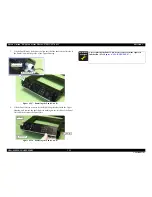
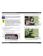
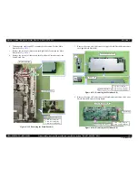
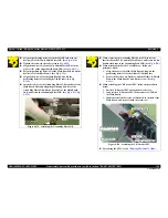
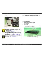
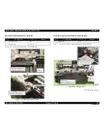
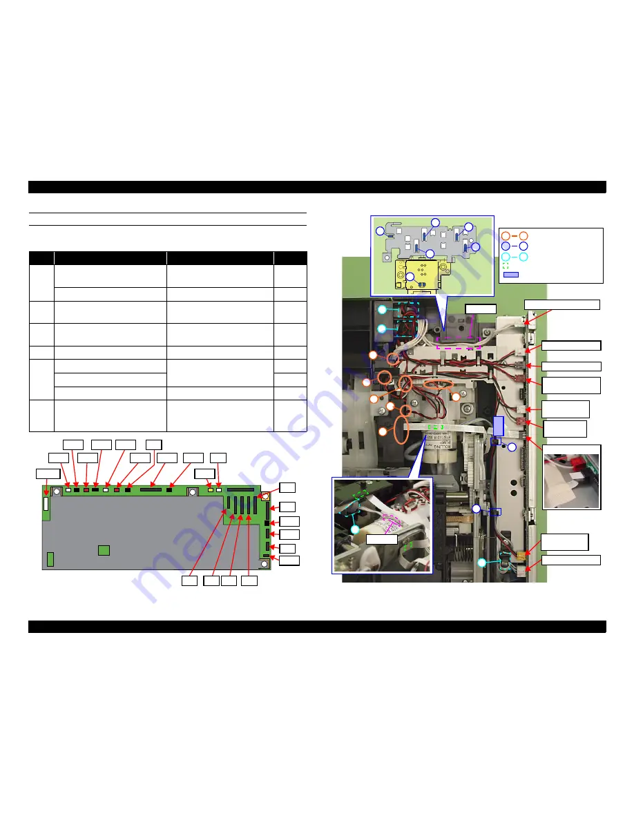
MAIN BOARD (TOP SIDE) (ARTISAN 700/PX700W/TX700W)
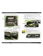
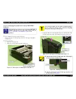
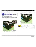
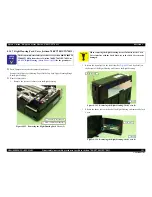
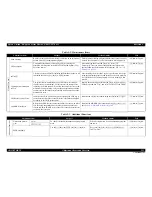
Following describes routing the cables and FFCs that connect to the Main Board.
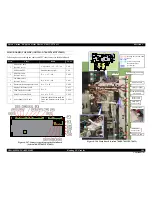
Figure 4-247. Connector positions on the Main Board
(Artisan 700/PX700W/TX700W)
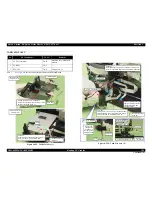
Figure 4-248. Main Board (Artisan 700/PX700W/TX700W)
Start
Cable
Route
CN No.
1
PE Sensor Cable
(Ferrite Core x2)
a
→
groove A
→
F
→
G
→
b
CN9
PF Encoder FFC
Double-sided tape (x4)
CN8
2
PF Motor Cable
(Ferrite Core x1)
E
→
c
→
C
→
B
CN22
3
CR Motor Cable
(Ferrite Core x1)
H
→
d
→
C
→
B
CN21
4
Decompression Pump Motor Cable
H
→
C
→
B
CN24
5
Duplex Unit Sensor Cable
D
→
A
CN13
CDR Tray Sensor Cable
CN14
Photo Tray Sensor Cable
D
→
A
→
F
→
G
CN12
6
Power Supply Unit Cable
Groove B (Insert it between Base
Frame and Decompression Pump
Unit)
CN501
CN501
CN22
CN21
CN24
CN49
CN14
CN8
CN41
CN10
CN12
CN9
CN6
CN4 CN3
CN2
CN1
CN5
CN19
CN31
CN7
CN32
CN13
G
1
2
3
4
5
6
b
d
c
a
Groove A
A
B
C
E
D
H
A
H
a
d
1
6
Groove B
F
Power Supply Unit Cable
PF Motor Cable
CR Motor Cable
Decompression Pump
Motor Cable
Duplex Unit
Sensor Cable
CDR Tray
Sensor Cable
PE Sensor Cable
Photo Tray
Sensor Cable
Hook
Double-sided tape
Ferrite Core position
Routing hole for FFC/cable
PF Encoder FFC
Acetate tape
Summary of Contents for Artisan 700 Series
Page 7: ...Confidential C H A P T E R 1 PRODUCTDESCRIPTION ...
Page 42: ...Confidential C H A P T E R 2 OPERATINGPRINCIPLES ...
Page 48: ...Confidential C H A P T E R 3 TROUBLESHOOTING ...
Page 189: ...Confidential C H A P T E R 5 ADJUSTMENT ...


