Manual
Appendix
A.1 CONNECTOR SUMMARY
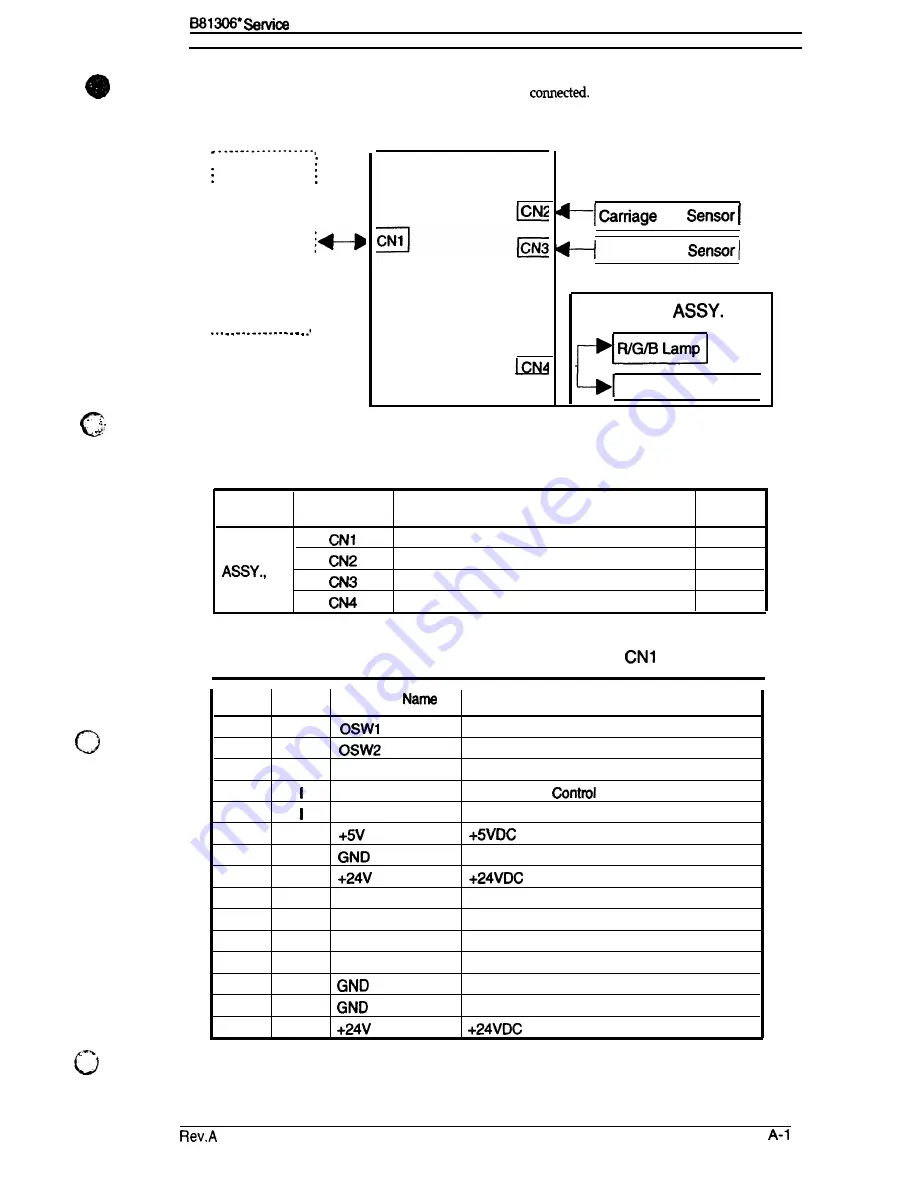
Figure A-1 illustrates how the primary components are
Table A-1 summarizes the
functions and sizes of the connectors.
SCANNER
,
B81306* MAIN Board
HP
Cover Open
CARRIAGE
CARRIAGE MOTOR I
Figure A-1. Cable Connections
Table A-1. Connector Summary
Board
Connector
Function
Pins
Interface
15
BOARD
HP Sensor
3
MAIN
Cover Open Sensor
2
LAMP, CARRIAGE MOTOR
13
Table A-2. Connector Pin Assignments -
Pin
I/o
Signal
Function
1
0
Carriage Home Position Signal
2
0
Cover Open Signal
3
I
B
Blue
Lamp Control
4
G
Green Lamp
5
R
Red Lamp Control
6
-
7
-
Ground
8
-
9
T)(D
Transmitted Data
10
SCK
Option Clock
11
LOO
Option Control
12
SEL
Select Signal
13
-
Ground
14
-
Ground
15
-
Summary of Contents for B81306 series
Page 1: ...TRANSPARENCY UNIT B81306 FOR EPSON IMAGE SCANNER SERVICE MANUAL EPSON ...
Page 5: ...REVISION SHEET b Revision Issue Date Revision Page Rev A November 28 1994 Ist issue c L v ...
Page 22: ...CHAPTER 4 Adjustments The transparency unit is not need any adjustment ...
Page 32: ...B81306 SeMce Manual Appendix A 4 EXPLODED DIAGRAM m Figure A 4 Exploded Diagram 1 Rev A A 5 ...


