


EPSON OVERSEAS
MARKETING LOCATIONS
1
EPSON AMERICA. INC.
2780 Lomita Blvd..
Torrance, Calif. 90505. U.S.A
P h o n e : ( 2 1 3 ) 5 3 9 - 9 1 4 0
Fax: (213) 534-5654
E P S O N D E U T S C H L A N D G m b H
6. 4000
1 1
F.R. Germany
Phone: 10211) 56030
T e l e x : 6 5 8 4 7 6 6
EPSON UK LTD.
Campus 100. Maylands Avenue.
HP2
U.K.
Phone:
Telex. 5 162467
EPSON FRANCE S. A.
68 bis.
9 2 3 0 0 .
France
P h o n e :
4 7 - 3 7 3 3 3 3
T e l e x . 6 1 0 6 5 7
EPSON AUSTRALIA PTY. LTD.
17 Rodborough Road.
Forest. NSW 2066,
P h o n e :
(2)
EPSON SINGAPORE PTE. LTD.
No. 1 Raffles Place #26-00
OUB
Singapore 0104
Phone: 533-0477
Fax: 533-6119
EPSON ELECTRONICS TRADING LTD. EPSON ELECTRONICS TRADING LTD.
25/F.
(TAIWAN BRANCH)
25
Road.
No. 287
E. Road Sec. 3.
Hong Kong
Taipei. Taiwan. R.O.C.
P h o n e : 5 - 6 3 1 4 6 0 0
Phone: (02) 717-7360
T e l e x : 6 5 5 4 2
Fax: (02) 712-9164
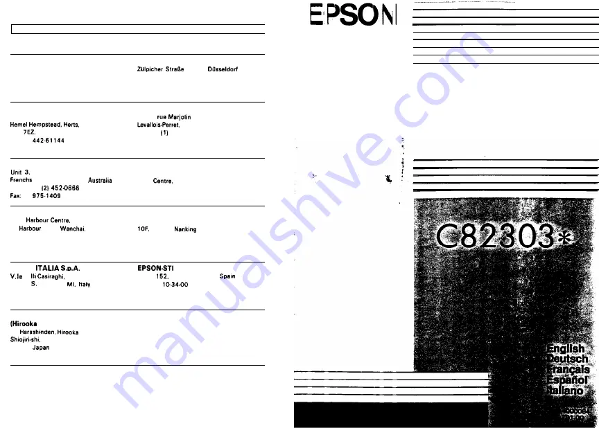
EPSON
F.
4 2 7 2 0 0 9 9
SESTO
GIOVANNI
P h o n e : 2 . 2 6 2 3 3 ,
F a x : 2 . 2 4 4 0 7 5 0
S.A.
Pans.
08036 Barcelona.
Phone: 4
Fax: 239-95-17
SEIKO EPSON COR
PORATION
Office)
8 0
Nagano-ken
3 9 9 . 0 7
P h o n e : ( 0 2 6 3 ) 5 2 . 2 5 5 2
32KB
Parallel Interface
1989 July
Printed in Japan 89.12-.4
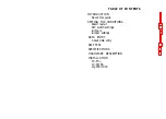
Summary of Contents for C82303
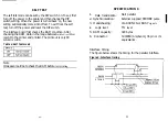
Page 18: ...L xda xiI Xii NOILV IWLSNI 3 ...
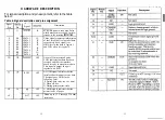
Page 19: ...C 000T 008 iTI we 98 08 X1 ...


