background image

Summary of Contents for DFX-5000+

Page 1: ......

Page 2: ......

Page 3: ......

Page 4: ...ous a deux personnes pour la transporter ou la soulever comme indique ci dessus Ne pas essayer d enlever le cordon élastique des tracteurs avant ou arrière Cen est pas un matériau de protection NOTA Si tiene que mover o transportar esta impresora no lo haga sólo levántela con ayuda de otra persona sujetándola por la base tal como se indica en la ilustración No intente retirar el cable elástico de1...

Page 5: ...tirer avant de l installer NOTA L imballaggio della vostra stampante contiene molti elementi protettivi per prevenire danni durante il trasporto Non dimenticate di toglierli prima di iniziare a utilizzare la stampante NOTA Para evitar darios durante el transporte su impresora viene protegida por varias piezas de material protector Debe retirar estas piezas antes de montar su impresora Please also ...

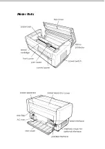
Page 6: ...Printer Parts ...

Page 7: ...ccident misuse or abuse of this product or unauthorized modifications repairs or alterations to this product or excluding the US failure to strictly comply with Seiko Epson Corporation s operating and maintenance instructions Seiko Epson Corporation shah not be liable against any damages or problems arising from the use of any options or any consumable products other than those designated as Origi...

Page 8: ... different from that to which the receiver is connected Consult the dealer or an experienced radio TV technician for help WARNING The connection of a non shielded equipment interface cable to this equipment will invalidate the FCC Certification of this device and may cause interference levels which exceed the limits established by the FCC for this equipment It is the responsibility of the user to ...

Page 9: ...t Unpacking the Printer Checking the parts Removing the protective materials Choosing a Place for the Printer Installing the Ribbon Cartridge Plugging in the Printer Testing the Printer Loading paper onto the front tractor Running the self test Connecting the Printer to Your Computer Connecting the built in interface Using Software Programs Microsoft Windows 3 1 What is a Printer Driver Non Window...

Page 10: ...Between Front and Rear Tractors 2 19 Changing the Paper 2 21 Printing on Multi part Forms and Labels 2 24 Using multi part forms 2 25 Using labels 2 26 Chapter 3 Using the Printer The Control Panel 3 2 Indicator lights 3 2 Buttons 3 3 Other control panel features 3 7 Using DIP Switches 3 7 Changing DIP switch settings 3 8 DIP switch tables 3 10 DIP switch functions 3 14 Printer mode 3 14 Draft pri...

Page 11: ...tor with the front tractor 4 5 Using the pull tractor with the rear tractor 4 9 Removing the pull tractor 4 12 Optional Interface Cards 4 14 Installing an interface card 4 15 Chapter 5 Troubleshooting and Maintenance Error Indicators 5 2 Problems and Solutions 5 3 The printer does not print 5 3 The printer stops printing 5 4 The printout is spaced incorrectly 5 4 The printout is faint or uneven 5 ...

Page 12: ...terface A 13 Optional interfaces A 14 Initialization A 14 Top of form reset A 15 Appendix B Printer Commands and Character Tables Sending Printer Commands B 2 Using the Command Summary B 2 Epson ESC P Commands Arranged by Topic B 3 IBM Emulation Mode Commands Arranged by Topic B 9 Commands that duplicate Epson ESC P commands B 10 Commands that differ from Epson ESC P commands B 11 Character Tables...

Page 13: ...r 2 Use the rest of this user s guide as a reference for enhancing print quality using printer options and troubleshooting printer problems Features Here are some of the features that make your printer unique Extra fast printing speeds Up to 560 characters per second in draft mode Two built in push tractors front and rear for convenient paper handling This dual system lets you switch between diffe...

Page 14: ...to the top of the page so it is ready to print An automatic interface selection feature that allows you to connect more than one computer at a time Compatibility with the Epson ESC P commands used by Epson FX printers An IBM Proprinter emulation mode that provides compatibility with software written specifically for IBM printers Options The following options are available for use with your printer...

Page 15: ... United States Users Can Get Help Epson America provides local customer support and service through a nationwide network of authorized Epson dealers and Service Centers Epson also provides the following support services through the Epson ConnectionSM at 800 922 8911 Assistance in locating your nearest Authorized Epson Reseller or Service Center Technical assistance with the installation configurat...

Page 16: ... to furnish such proof Epson UK Limited does not issue or operate any form of guarantee registration card Claims are made by the user returning the product to the supplier from whom it was purchased or if this is impractical to any Epson supplier who also handles the same product In the event of any difficulty users are requested to contact the Service Co ordinator Manager at Epson UK Limited Epso...

Page 17: ...he guarantee does not cover visits to the user s premises or the repair or commissioning of the product on site Use of options Epson UK Limited shall not be liable against any damages or problems arising from the use of any options or consumable products other than those designated as Original Epson Products or Epson Approved Products by Epson UK Limited Safety information Warning This appliance m...

Page 18: ...e terminal in the plug marked with the letter L or coloured red If damage occurs to the plug replace the cord set or consult a qualified electrician Replace fuses only with a fuse of the correct size and rating Important Safety Instructions Read all of these instructions before you set up your printer Follow all warnings and instructions marked on the printer Unplug the printer from the wall outle...

Page 19: ...u are unable to insert the plug into the outlet have an electrician replace your obsolete outlet Do not defeat the purpose of the grounding type plug Do not put your printer where the cord wiIl be walked on If you use an extension cord make sure that the total of the ampere ratings on the products plugged into the extension cord does not exceed the extension cord s ampere rating Also make sure tha...

Page 20: ...perating instructions since improper adjustment of other controls may result in damage and will often require extensive work by a qualified technician to restore the printer to normal operation If it has been dropped or the cabinet has been damaged If it exhibits a distinct change in performance indicating a need for service Warnings Cautions and Notes Warnings must be followed carefully to avoid ...

Page 21: ...tridge l 6 Plugging in the Printer l 10 Testing the Printer 1 11 Loading paper onto the front tractor 1 12 Running the self test 1 18 Connecting the Printer to Your Computer l 20 Connecting the built in interface l 21 Using Software Programs l 24 Microsoft Windows 3 1 l 24 What is a Printer Driver l 26 Non Windows Software 1 26 You re Ready to Print l 27 Set Up and Print 1 1 ...

Page 22: ...tridge l 6 Plugging in the Printer l 10 Testing the Printer 1 11 Loading paper onto the front tractor l 12 Running the self test l 18 Connecting the Printer to Your Computer l 20 Connecting the built in interface l 21 Using Software Programs l 24 Microsoft Windows 3 1 l 24 What is a Printer Driver l 26 Non Windows Software l 26 You re Ready to Print l 27 Set Up and Print 1 1 ...

Page 23: ...Unpacking the Printer Because the printer weighs approximately 29 kg 64 lb you should not lift or carry it by yourself Two people should carry it lifting from the bottom 1 2 Set Up and Print ...

Page 24: ...e printer store the packing materials in case you ever need to transport the printer Removing the protective materials The printer is protected during shipping by several pieces of packing material that must be removed before you turn on the printer Please see the Notice Sheet inserted in your printer for instructions on removing the protective materials Then store them with the other packing mate...

Page 25: ... stacks of continuous paper as well as your printed output Use a grounded outlet do not use an adapter plug Avoid locations that are subject to direct sunlight excessive heat moisture or dust Avoid using electrical outlets that are controlled by wall switches or automatic timers Accidental disruption of power can wipe out information in both your computer s memory and your printer s memory Avoid u...

Page 26: ...rts at least 58 kg 128 lb Never use a stand that tilts the printer It should always be kept level Make sure to provide enough clearance below the stand and between the legs so your continuous paper feeds smoothly Place cables so they do not interfere with paper feeding secure them to a leg of the stand if possible Set Up and Print 1 5 ...

Page 27: ...n cartridge from its box and plastic wrapper and then follow these steps 1 Open the top cover by gently lifting its front edge up and away from you Warning Never move the print head while the printer is turned on because this can damage the printer Also if you have been using the printer the print head may be hot let it cool for a few minutes before touching it 1 6 Set Up and Print ...

Page 28: ...hown below 3 Remove and throw away the plastic separator from the middle of the ribbon cartridge Next detach the ribbon guide from the cartridge and turn the ribbon tightening knob in the direction of the arrow to take up any slack in the ribbon Set Up and Print 1 7 ...

Page 29: ... toward you slide the slots nearest you over the corresponding two pins in the printer Then push the cartridge down into position until the other two slots snap into place over the mounting pins in the printer 5 Press lightly on both sides of the cartridge to make sure it is locked in place 1 8 Set Up and Print ...

Page 30: ...aller end of the guide should be on top with its angled edge facing back toward the platen Turn the ribbon tightening knob again to remove any slack in the ribbon 7 Slide the print head from side to side to see that it moves smoothly and that the ribbon is not twisted or creased Set Up and Print 1 9 ...

Page 31: ...ower switch located on the lower right side of the printer should be visible 2 Check the label on the printer s rear panel to see if the voltage required by the printer matches that of your electrical outlet If it does not match contact your Epson dealer without connecting the power cord 1 10 Set Up and Print ...

Page 32: ... the power wait at least five seconds before turning it back on otherwise you may damage the printer Testing the Printer Now that your printer is fully assembled you can use your printer s built in test function to be sure the printer is working correctly before you connect it to a computer Before performing the test you need to load paper Set Up and Print 1 11 ...

Page 33: ...fting the middle of its bottom edge up until it locks in place as shown below 2 Release the sprocket lock levers on both the right and left sprocket units by pulling each lever down Caution Do not try to pull on or remove the elastic cord from the tractor 1 12 Set Up and Print ...

Page 34: ...cket unit all the way to the left Lock it into place by pushing the sprocket lock lever up 4 Now slide the right sprocket unit to approximately match the width of your paper Do not lock it in place yet Set Up and Print 1 13 ...

Page 35: ...5 Slide the two paper supports so that they are spaced evenly between the sprocket units 6 Open both sprocket covers 1 14 Set up and Print ...

Page 36: ...of the sprocket units as shown below The side of the paper that you want to print on should be facing you Now close the sprocket covers 8 Slide the right sprocket unit so that the paper is straight and has no wrinkles Lock the sprocket unit in place by pushing the sprocket lock lever up Set Up and Print 1 15 ...

Page 37: ...ull out slightly on the printer s front cover and lower it until it is closed Caution Do not push down on the front cover always pull it out slightly before closing Before turning on the printer be absolutely sure you have removed all protective materials Turning on the printer while the print head cannot move may seriously damage the mechanism 1 16 Set Up and Print ...

Page 38: ... or rear tractor arrow on the PAPER SELECT indicator lights up 11 Press the LF FF LOAD button to load your paper If the paper does not load the front tractor may not be selected Press the FRONT REAR button to select the front tractor This loads the paper automatically 12 After the paper loads turn off the printer Set Up and Print 1 17 ...

Page 39: ... printout in high speed draft Note When NLQ quality is selected using DIP switch l 3 the serf test runs in NLQ mode even if you press the LF FF button 2 The self test continues until the paper runs out or until you press the PA USE button If the test results are satisfactory and you wish to stop the test press the PAUSE button To resume the test press the PAUSE button again 3 To end the self test ...

Page 40: ...printer beeps four times stops printing and goes into pause status To resume printing close the top cover and press the PAUSE button You can select normal draft mode or high speed draft mode using DIP switch 1 2 For details see Chapter 3 If continuous paper is fed past the sprocket on the last page for example the paper may not feed properly Set Up and Print 1 19 ...

Page 41: ...ur computer check your computer manual Note Your printer has an automatic interface selection feature that allows you to connect more than one interface to the printer at a time See the section on using automatic interface selection in Chapter 3 If you have a suitable shielded cable you should be able to connect the printer immediately If you have one of the few computers that requires a different...

Page 42: ...or either the built in parallel or serial interface 1 Turn off both your printer and computer 2 Open the rear cover by grasping it by the handholds on each side 3 Plug the cable connector securely into the parallel or serial interface Set Up and Print 1 21 ...

Page 43: ... wire clips together until they lock in place on either side of the connector If your cable has a ground wire connect it to the printer s ground connector When you connect the serial interface fasten the screw on the cable connector 1 22 Set Up and Print ...

Page 44: ...terface replace the lock nuts with the optional lock nuts provided with the printer 5 Open the plastic clamp to the right of the interface connectors by pulling out its top tab Insert the cable in the plastic clamp and close the clamp as shown below 6 Close the rear cover Set Up and Print 1 23 ...

Page 45: ... switches in Chapter 3 for more information Using Software Programs To take full advantage of your printer s features find the instructions for your software programs below Microsoft Windows TM 3 1 If Windows is already installed on your system follow the steps below to set it up with your printer Then your printer will work correctly for all your Windows programs such as Word for Windows and Lotu...

Page 46: ...ruct you to insert a diskette If necessary insert the diskette required Choose the Setup button Choose the OK button Highlight Epson DFX 5000 or the printer you added and click the button labeled Set As Default Printer 10 Click the Close button You have now installed the printer driver for Windows Note To use 15 characters per inch on your printer you need the DFX 5000 driver If your version of Wi...

Page 47: ...s Software Most software programs let you specify the type of printer you are using so that the program can take full advantage of the printer s features If your application program has an installation or setup procedure that lets you select your printer from a list of printers choose the Epson DFX 5000 printer If the list does not include the DFX 5000 choose one of the following printers listed i...

Page 48: ...about your printer such as loading different paper types look for the appropriate topic in other chapters in this user s guide Caution Running the printer continuously for extended periods of time is not recommended It can cause the printer to wear out sooner than expected Set Up and Print 1 27 ...

Page 49: ...ing the top of form position 2 11 Adjusting the printing position 2 13 Tearing Off the Printed Pages 2 14 Tear off mode 2 14 Using the TEAR OFF button 2 16 Adjusting the tear off position 2 16 Switching Between Front and Rear Tractors 2 19 Changing the Paper 2 21 Printing on Multi Part Forms and Labels 2 24 Using multi part forms 2 25 Using labels 2 26 Loading and Using Paper 2 1 ...

Page 50: ...ost often onto the rear tractor That way you can reserve the front tractor which is easier to reach for the paper you change more frequently Use only the front tractor for printing on labels Caution Before using your paper check that it matches the specifications described in Appendix A Also check that your paper has a straight edge Note If continuous paper is fed past the sprocket on the last pag...

Page 51: ... Paper onto the Rear Tractor The following steps show you how to load paper onto the rear tractor You do not need to remove the paper from the front tractor first because the printer does this for you when you select the rear tractor Note If you performed a self test as described in Chapter 1 you loaded continuous paper onto the front tractor If you did not run a self test see Loading paper onto t...

Page 52: ...2 Open the printer s top cover by gently lifting its front edge up and away from you as shown below 3 Open the rear flap at the back of the top cover 2 4 Loading and Using Paper ...

Page 53: ...nd left sprocket units by pushing each lever back Caution Do not try to pull on or remove the elastic cord from the tractor 5 Slide the left sprocket unit all the way to the left Lock it in place by pulling the sprocket lock lever forward Loading and Using Paper 2 5 ...

Page 54: ...the right sprocket unit to approximately match the width of your paper Do not lock it in place yet 7 Slide the two paper supports so they are spaced evenly between the two sprocket units 2 6 Loading and Using Paper ...

Page 55: ...paper you want to print on facing down insert your paper through the opening at the rear You may find it easier to load the paper by standing to the side of the printer That way you can feed the paper into the rear opening with one hand and pull it through with the other Loading and Using Paper 2 7 ...

Page 56: ...e sprocket units as shown below NOW close the sprocket covers 11 Slide the right sprocket unit to a position so that the paper is straight and has no wrinkles Lock the sprocket unit in place by pulling the sprocket lock lever forward 2 8 Loading and Using Paper ...

Page 57: ...op cover and the rear flap The paper is now loaded to the standby position 13 Turn on the printer The print head moves to the left of the printer and the POWER and PAPER OUT lights go on Also either the front or rear tractor arrow on the PAPER SELECT indicator lights up depending on which tractor was selected when the printer was turned off last Loading and Using Paper 2 9 ...

Page 58: ...ded to the top of form position If it looks like the printing will start too high or low on the page see the next section for instructions on adjusting the paper position Adjusting the Paper Position You can adjust the top of form position as well as the printing position at any point on the page by using the TOP OF FORM and MICRO FEED buttons The printer then remembers the new top of form positio...

Page 59: ... the top of form position you enter the top of form mode using the TOP OF FORM control panel button The printer remembers the new top of form position even after the printer is turned off reset or initialized The printer remembers separate top of form positions for the front and rear tractors When you want to temporarily change the top of form position you adjust the position using the MICRO FEED ...

Page 60: ...er top of form mode The printer beeps once and the TOP OF FORM light flashes Also the printer advances the paper so that the top of form position is lined up with the red line on the clear plastic ribbon protector Open the top cover Use the MICRO FEED buttons to feed the paper to the desired top of form position The to pedge of the ribbon protector shows you where the bottom edge of your first lin...

Page 61: ... position when using labels follow the steps below When you move the printing position you temporarily change the top of form position by the same amount For example if you adjust the printing in the middle of the page so that it falls a half inch lower the next page will begin printing a half inch lower as well The printer remembers this temporary top of form position until the next time you load...

Page 62: ... lost between documents You can use the tear off feature in two ways by turning on DIP switch 3 8 to select automatic tear off mode or by pressing the TEAR OFF button on the control panel If the perforation between pages is not aligned with the tear off edge you can adjust the tear off position using the micro feed feature The printer remembers this new tear off position Caution Never use the fear...

Page 63: ...ff mode is on and you print on continuous paper on the push tractor the printer advances the final printed page to the tear off position Then you can tear off all printed pages If the perforation is not aligned with the tear off edge adjust the tear off position as described in the section on adjusting the tear off position When you resume printing the printer automatically feeds the paper back to...

Page 64: ...inted pages If the perforation is not aligned with the tear off edge adjust the tear off position as described in the next section 3 When you resume printing the printer automatically feeds the paper back to the loading position and begins printing You can also manually feed the paper back to the loading position by pressing the TEAR OFF button again Adjusting the tear off position If the paper s ...

Page 65: ...art of the printer s top cover This exposes the printer s tear off edge 3 Press the TEAR OFF button to enter the tear off mode The TEAR OFF light goes on and the printer feeds the paper s perforation to the printer s tear off edge Loading and Using Paper 2 17 ...

Page 66: ...RO FEED button to feed the paper Note You can reset the tear off position only when you are in tear off mode after you press the TEAR OFF button once and the TEAR OFF light is on The printer remembers the new tear off position even after the printer is turned off reset or initialized 5 Tear off the page using the tear off edge on the printer s top cover 2 18 Loading and Using Paper ...

Page 67: ... but you can follow the same steps to switch from the rear tractor to the front tractor To switch tractors when the optional pull tractor is installed see Chapter 4 Caution Never switch between tractors when labels are already loaded in the printer Instead completely remove the labels first by tearing off the fresh supply below the tractor and pressing LF FF to eject the remaining labels Before yo...

Page 68: ...ing on page 2 3 2 If you have a printed document or excess paper still in the printer use the tear off feature described in the previous section to tear off the document or excess paper Caution Always tear off the printed document and any excess paper before witching tractors Never feed more than one page backward through the printer 2 20 Loading and Using Paper ...

Page 69: ...ge the paper on the rear tractor Before you start make sure the printer is turned on and the front tractor is selected If you are changing the paper on the rear tractor the rear tractor should be selected instead Caution Never change paper using the following procedure if labels are already loaded in the printer Instead completely remove the labels first by tearing off the fresh supply below the t...

Page 70: ... document or excess paper Caution Always tear off printed documents before changing the paper Never feed more than one page backward through the printer 2 Press the FRONT REAR button to switch to the rear tractor The front loaded paper automatically feeds back to the standby position 2 22 Loading and Using Paper ...

Page 71: ...Open the printer s front cover To change the rear loaded paper open the printer s top cover and the rear flap 4 Open the sprocket covers and remove the paper from the tractor Loading and Using Paper 2 23 ...

Page 72: ...inter automatically adjusts to the width and thickness of your paper When you print on multi part forms and labels the positioning of your text on the page can be critical For more information on aligning your text see the sections on adjusting top of form and printing positions earlier in this chapter You should also check both your printer and your software page length settings before you load l...

Page 73: ...way you load any other type of continuous paper Before loading multi part forms however make sure the paper has a clean straight edge and does not separate or tear apart See the sections on loading paper earlier in this chapter When you use the paper memory feature described in Chapter 3 the DFX 5000 can print on multi part forms that vary in thickness such as forms with labels on them or forms th...

Page 74: ... the TEAR OFF FRONT REAR or reverse feeding bottom MICRO FEED button when labels are loaded in the printer Labels must never be fed backward through the printer because they can easily come off the backing and jam the printer Although you must never feed labels backward through the printer you can still use the automatic paper handling features if you follow these precautions Instead of using the ...

Page 75: ...r printing position use only the forward feeding top MICRO FEED button Caution Because labels are especially sensitive to extreme temperatures and humidity always use them under normal operating conditions Loading and Using Paper 2 27 ...

Page 76: ...r quality 3 15 Character table 3 15 Shape of zero 3 15 Input buffer 3 16 Auto line feed 3 16 Interface type parity 3 16 Serial bit rate 3 17 Page length 3 17 Skip over perforation 3 18 Paper memory overlapping multi part forms multi part forms with labels 3 18 Skip over binding 3 18 Automatic tear off 3 18 Using Automatic Interface Selection 3 19 Using the Paper Memory Feature 3 19 Saving paper me...

Page 77: ...henever no paper is positioned behind the print head even if paper is loaded on the tractors in the standby position Flashes when the paper jams PAUSE On when printing is paused TEAR OFF On when the printer is in tear off mode The printer remembers any change you make to the tear off position when this light is on TOP OF FORM Flashes when the printer is in top of form mode The printer remembers an...

Page 78: ...ront tractor is selected The light is green when paper is loaded even if the paper is in the standby position and red when the tractor is out of paper On when the rear tractor is selected The light is green when paper is loaded even if the paper is in the standby position and red when the tractor is out of paper PAUSE Controls whether the printer can print or not Press this button to stop or start...

Page 79: ...ning the self test in Chapter 1 Feeds the paper to the printer s tear off edge and puts the printer in tear off mode If the perforation of your paper does not align exactly with the printer s tear off edge use the MICRO FEED buttons to adjust the tear off position See the section on adjusting the tear off position in Chapter 2 This button can also be used to run the printer s NLQ self test See the...

Page 80: ...n press the TEAR OFF button to enter tear off mode and feed the paper to the tear off position Then use the MICRO FEED buttons to move the paper to the desired position See the section on adjusting the tear off position in Chapter 2 To adjust the printing position press either MICRO FEED button to advance or reverse the paper to the desired position See the section on adjusting the printing positi...

Page 81: ...position in Chapter 2 Lets you select the characters per inch for printing Push the button until the light appears next to your preference Your software setting overrides this setting PAPER SELECT FRONT REAR Lets you select the front or rear tractor If you have been using paper loaded on one tractor first remove the printed output before pressing this button to switch the tractor When you switch b...

Page 82: ...on problems between the computer and printer See the section on the hex dump mode in Chapter 5 for more information Print settings By holding down the PAUSE button while you turn on the printer the printer prints the current DIP switch settings Using DIP Switches This printer has three sets of DIP switches DIP switches control a variety of printer functions such as page length and printing speed D...

Page 83: ...e printer 2 Open the printer s front cover by lifting the middle of its bottom edge up until it locks in place 3 The DIP switches are located in a small compartment on the front paper guide behind the front tractor paper If paper is loaded on the front tractor either remove it or lift it up out of the way so you can reach the DIP switches 3 8 Using the Printer ...

Page 84: ...rument such as the tip of a ballpoint pen to turn the switch either on or off A DIP switch is on when it is up and off when it is down Note Always make sure that the printer is turned off before changing the DIP switch settings Using the Printer 3 9 ...

Page 85: ...ch tables The following tables show the settings for each DIP switch For more information about each feature see the explanations following the DIP switch tables DIP switch 1 Switch Description 1 1 Printer mode 1 2 Draft printing speed 1 3 Character quality 1 4 Character table 1 5 in Epson ESC P mode 1 6 1 7 For setting in IBM mode see table E 1 8 IBM Pro Printer II emulation ON OFF IBM ESC P Norm...

Page 86: ...Serial bit rate See table C 2 8 DIP switch 3 Switch Description O N OFF 3 1 Page lenght See table D 3 2 3 3 Skip over perforation Skip No skip 3 4 Paper memory Memory 2 Memory 1 3 5 Overlapping multi part forms Yes N o 3 6 Multi part forms with label Yes N o 3 7 Skip over binding Y e s N o 3 8 Automatic tear off Yes N o These switches are for paper memory settings Using the Printer 3 11 ...

Page 87: ...Table A Epson ESC P mode only Available in the European version only PC437 is selected by all other switch combinations 3 12 Using the Printer ...

Page 88: ... ON OFF OFF ON ON ON OFF OFF Serial odd parity ON OFF ON ON ON OFF Serial even parity Serial no parity ON ON ON The printer waits this interval after a print job before it accepts data from another interface Table C Serial bit rate Bit rate 19200 9600 1200 300 SW 2 7 SW 2 8 OFF OFF OFF ON ON OFF ON ON Table D Page length Page length 11 inches 12 inches 8 5 inches 70 6 inches SW 3 l SW 3 2 OFF OFF ...

Page 89: ...DIP switches l 4 1 5 1 6 1 7 and l 8 in IBM mode Table A shows the functions of those same DIP switches in ESC P mode Draft printing speed When DIP switch l 2 is off high speed draft mode is selected When this switch is on normal draft mode is selected This switch affects the printer only if DIP switch l 3 is set to draft mode turned off or if draft mode is selected in your software In high speed ...

Page 90: ...it prints in draft mode This is NLQ printing T h i s i s n o r m a l d r a f t p r i n t i n g Character table When DIP switch l l is off and DIP switches l 4 through 1 8 are set on and off in various combinations you can select the character tables available in the Epson ESC P mode When DIP switch l l is on and DIP switches l 6 or l 8 are on or off you can select character table settings in IBM e...

Page 91: ... line feed commands to the printer Since most computers and application programs automatically add line feeds to carriage returns you should use this feature only if your text is printing all on one line Note If you select auto line feed but your text still prints on one line you need to disable the AUTO FEED XT signal See your Epson dealer for assistance Interface type parity You may need to chan...

Page 92: ...sure your computer and printer have the same parity setting Serial bit rate Besides selecting the interface and parity if your computer is set up for serial communications you may also need to change the serial bit also known as baud rate setting The serial bit rate is the rate at which the printer receives data from the computer Table C shown earlier has the DIP switch settings for the printer s ...

Page 93: ...g multi part forms multi part forms with labels By setting DIP switches 3 4 through 3 6 you can print on multi part forms that vary in thickness See the section on using the paper memory feature later in this chapter Skip over binding When DIP switch 3 7 is on the print head avoids the binding area along the right and left edges of multi part forms during paper feeding thus avoiding paper jams Aut...

Page 94: ... built in serial interface if you have installed an optional serial interface card C82305 C82306 the optional card overrides the built in interface If the DIP switch on the optional card is set to disable you can use the built in serial interface Using the Paper Memory Feature When you use multi part forms that overlap or forms with labels on them use the paper memory feature for better print qual...

Page 95: ...s Saving paper memory settings This procedure requires setting several DIP switches See the section on changing DIP switch settings earlier in this chapter 1 2 3 4 Make sure the printer is turned off Turn DIP switch 3 4 off to save your settings for memory number 1 or on for memory number 2 Select the page length by turning DIP switches 3 1 and 3 2 on or off as shown below Page length SW 3 1 SW 3 ...

Page 96: ...shed all steps for saving information on overlapping multi part forms without a label For regular and overlapping multi part forms with a label hold down both MICRO FEED buttons and turn on the printer The printer beeps Press the LF FF LOAD button to load the forms The printer loads and checks the forms When the check is finished the printer beeps continuously until you open the top cover in the n...

Page 97: ...er beeps one or two times the settings were saved If the printer beeps ten times the settings were not saved In this case turn off the printer and repeat steps 5 through 11 Loading paper memory settings 1 Make sure the printer is turned off 2 To recall the memory 1 setting hold down the top MICRO FEED button while you turn on the printer To recall the memory 2 setting hold down the bottom MICRO FE...

Page 98: ...aper memory settings 1 or 2 for a particular job simply hold down the FRONT REAR button while you turn on the printer A one inch skip over perforation is automatically included for overlapping multi part forms Using the Printer 3 23 ...

Page 99: ... 4 2 Installing the pull tractor 4 2 Using the pull tractor with the front tractor 4 5 Using the pull tractor with the rear tractor 4 9 Removing the pull tractor 4 12 Optional Interface Cards 4 14 Installing an interface card 4 15 Using the Printer Options 4 1 ...

Page 100: ...with either the printer s front or rear built in tractor as described in this section Installing the pull tractor To install the pull tractor you need a cross head screwdriver Note If you are going to be using the pull tractor with the built in rear tractor you should load paper onto the rear tractor before installing the pull tractor See the section on loading paper onto the rear tractor in Chapt...

Page 101: ...curing the paper separator to the printer Then lift the paper separator off the printer 3 Using the two screws you just removed from the printer s original paper separator install the paper separator that comes with the pull tractor Using the Printer Options 4 3 ...

Page 102: ...he paper separator cover and open the printer top cover 5 Holding the pull tractor with its gears to the left fit the tractor s front notches over the mounting shaft of the printer 4 4 Using the Printer Options ...

Page 103: ...tor If you are using labels or multi part forms with more than four parts including the original you should use the pull tractor with the printer s built in front tractor You can switch between the front and rear tractors at any time when you are using the pull tractor Just press the FRONT REAR button and then use the LF FF button to feed the paper the additional distance to the pull tractor Label...

Page 104: ...dy on the tractor but it is in the standby position press the FRONT REAR or LF FF button depending on which tractor is selected to load the paper to the top of form position If no paper is on the front tractor at all load paper as described in Chapter 1 Once you have paper loaded on the printer s front tractor use the LF FF button to advance the paper to the pull tractor Release both sprocket lock...

Page 105: ...5 Adjust the sprocket units to match the width of your paper 6 Slide the two paper supports so they are spaced evenly between the two sprocket units Using the Printer Options 4 7 ...

Page 106: ...e sprocket pins pull up the paper slightly and use the pull tractor knob to adjust the position of the paper as shown below Slide the knob to the right first and then turn it as necessary Caution Be sure the sprocket units of the built in front tractor and the optional pull tractor are aligned 8 Close the sprocket covers 4 8 Using the Printer Options ...

Page 107: ...ket unit and lock if again 10 Adjust the top of form position as described in Chapter 2 if necessary 11 Close the top cover Press the LF FF button to feed the paper out the back of the printer Make sure the edge of the first sheet emerges below the paper separator Using the pull tractor with the rear tractor If you are using labels or multi part forms with more than four parts including the origin...

Page 108: ...press the LF FF button to advance the paper to a point where it can be tom off The following steps show you how to load paper using the optional pull tractor already installed with the printer s built in rear tractor If you have not yet installed the pull tractor load paper onto the rear tractor and then install the pull tractor as described earlier in this chapter 1 Open the top cover Note If pap...

Page 109: ... 4 Load paper onto the rear tractor as described beginning on page 2 4 steps 3 through 11 5 Open the paper bail using the tab on its right side Then tilt the pull tractor back until the rear latches click into place over the printer s rear mounting pins Using the Printer Options 4 11 ...

Page 110: ...ss head screwdriver and the paper separator that was originally installed on the printer 1 Remove any paper installed on the tractor and turn off the printer 2 Open the top cover and locate the levers that lock the pull tractor in place on the printer Pull these levers forward to release the pull tractor Then lift the tractor up and out of the printer 4 12 Using the Printer Options ...

Page 111: ...and open the paper separator cover 4 Using a cross head screwdriver remove the paper separator that came with the pull tractor 5 Reinstall the original paper separator and close the paper separator cover Using the Printer Options 4 13 ...

Page 112: ...able the printer to communicate with an IBM minicomputer or mainframe via coax or twinax protocol This allows Epson printers to function as local IBM printers without the addition of any other circuitry or components The following Epson interfaces are compatible with your printer Not all of these interfaces are available in all countries Number Name C82305 C82306 Serial interface card C82307 C8230...

Page 113: ...en remove all power and interface cables from the printer 2 Turn your printer so that the rear cover faces you 3 Open the printer s rear cover 4 Be sure to set any switches and jumpers on the card as necessary See the interface cards manual for details Make sure that you set jumper JG to on or the card will not work properly To set the jumper to on cover both wires of the terminal with the rectang...

Page 114: ...rews securing the interface shield plate remove the shield plate 6 Slide the interface card into the grooves in the interface slot Push it in firmly to make sure it connects to the printer s internal socket 4 16 Using the Printer Options ...

Page 115: ...ith the card 8 Plug the connector cable into the interface card as shown 9 Plug the other end of the cable into your computer 10 Close the interface cover 11 Plug the power cord into your printer and an electrical outlet Using the Printer Options 4 17 ...

Page 116: ...ops printing 5 4 The printout is spaced incorrectly 5 4 The printout is faint or uneven 5 5 The printout is not what you expect 5 5 Paper does not feed properly 5 6 Hex Dump Mode 5 7 Maintaining the Printer 5 8 Cleaning the printer 5 8 Replacing the ribbon cartridge 5 9 Transporting the printer 5 11 Troubleshooting and Maintenance 5 1 ...

Page 117: ... Other paper errors Load paper Tear off any printed page when switching the tractors Top cover open Close the top cover and press the PAUSE button Paper memory l Redo the paper setting error memory setting Micro adjustment Stop pressing the limit reached continuous MICRO FEED button Other errors Turn off the printer and leave it about 10 minutes then turn on the printer again If the error occurs a...

Page 118: ...rely to the computer Check both ends of the cable between the printer and the computer Make sure that the PAUSE light is not lit If it is lit printing has been temporarily suspended Press the PAUSE button to continue Make sure the printer is not out of paper The tractor arrow on the PAPER SELECT indicator should be green Make sure the correct tractor arrow is lit on the PAPER SELECT indicator If t...

Page 119: ... tighten the ribbon or the section on replacing the ribbon later in this chapter The top cover may be open If the top cover is opened during printing the printer beeps four times and stops printing To resume printing close the top cover and press the PAUSE button If the printer stops and the beeper sounds turn the printer off and check for paper jams or other problems Turn it back on and try to pr...

Page 120: ... the head replaced Never attempt to replace the head yourself because other parts of the printer should be checked at the same time The printout is not what you expect The wrong character table may be selected See the section on selecting character tables with DIP switches in Chapter 3 You can also select the character table using software commands See Appendix B The printer may not be securely co...

Page 121: ...sing an optional interface card make sure that DIP switches on the printer are set for parallel regardless of whether the optional card is parallel or serial See the section on DIP switch settings for interface type in Chapter 3 Paper does not feed properly The paper may not be mounted on the sprockets correctly Make sure the sprocket holes of the paper fit correctly over the sprockets Make sure t...

Page 122: ...cation programs In hex dump mode all codes received by the printer are printed 1 To enter hex dump mode hold down both the LF FF and TEAR OFF buttons while you turn on the printer 2 Next run a software program even one you have written in any programming language and send a print job to the printer Your printer prints all the codes it receives in hexadecimal format as shown in the sample below Dat...

Page 123: ... of the printout sample 1B 40 1B 55 31 Each hex 1B represents the ESC code 40 represents 55 represents U and 31 represents the numeral 1 Check the first line of the right column and you will find a dot an sign another dot a U and a 1 If you look in Appendix B you will see that these are the commands to initialize the printer and turn on unidirectional mode Maintaining the Printer Cleaning the prin...

Page 124: ... or abrasive brush Do not spray the inside of the printer with lubricants Unsuitable oils can damage the mechanism Contact your Epson dealer if you think lubrication is needed Replacing the ribbon cartridge When your printing becomes too faint you need to replace the ribbon Use the 8766 Epson replacement cartridge only Warning If the printer has been used recently the print head may be hot Let if ...

Page 125: ...the print head as shown below 4 Pull up on the side of the ribbon cartridge as shown below to release it from the printer s mounting pins Remove the cartridge by lifting it up and away from you 5 10 Troubleshooting and Maintenance ...

Page 126: ...hen you need to carry the printer only a short distance do not carry it by yourself The printer should always be carried by two people holding the printer at the bottom 1 Turn off the printer and remove any paper loaded in the printer If any printer options are installed remove them 2 Unplug the power cord from the electric outlet and the back of the printer Disconnect the interface cable from the...

Page 127: ...rinting A 2 Paper Mechanical A 3 A 9 Electrical A 10 Environmental A 10 Safety approvals A 10 Interface Specifications A 11 Parallel interface A 11 Serial interface A 13 Optional interfaces A 14 Initialization A 14 Top of form reset A 15 Technical Specifications A 1 ...

Page 128: ...onal for graphics can also be switched to bidirectional by using the proper software command Line spacing l 6 inch 1 8 inch or programmable increments of l 216 inch Paper feed speed Continuously Intermittently Approx 17 ms line 10 inches per second Approx 26 ms line Note Feeding speed reduces to 6 inches per second when the optional pull tractor is mounted Printable columns Pitch Maximum printed c...

Page 129: ...ons Serif NLQ 10 12 15 17 The 15 cpi pitch is available only by sending software commands Character tables Europe Other countries Character sets Paper Continuous paper Printable area One italic and 20 graphics character tables One italic and 8 graphics character tables 13 international character sets Technical Specifications A 3 ...

Page 130: ...0 012 inches maximum 45 to 70 kg 14 to 22 lb 35 to 48 kg 11 to 15 lb x n n 8 and within the total thickness Labels Printable area printable area inside each label Size Backing sheet Width Length 63 5 mm W x 23 8 mm H 2 inches W x 15 16 inches H 101 mm W x 23 8 mm H 4 inches W x 15 16 inches H 101 mm W x 26 99 mm H 4 inches W x 17 16 inches H 101 to 406 mm 4 to 16 inches 88 9 mm 3 5 inches minimum ...

Page 131: ...ability Front Overlap length Total thickness Print area Overlap Weight Multi part Backing sheet Plain paper Front only 101 to 406 mm 4 to 16 inches 5 sheets 1 original 4 copies 10 mm 0 394 inches maximum 0 46 mm 0 018 inches maximum 0 71 mm 0 028 inches maximum including the backing sheet 35 to 48 kg 11 to 15 lb within the total thickness 45 to 70 kg 14 to 22 lb Technical Specifications A 5 ...

Page 132: ...Paper path Width Total thickness Weight Single Multi part Plain paper Front only 101 to 406 mm 4 to 16 inches 0 46 mm 0 018 inches maximum 45 to 70 kg 14 to 22 lb 35 to 48 kg 11 to 15 lb x n n 8 and within the total thickness A 6 Technical Specifications ...

Page 133: ...dges of the paper as shown below The edges of paper are not perforated At the perforation between pages the horizontal and vertical perforation cuts should not cross as shown here The ratio of the cut uncut length at the perforation should be less than 5 1 Expansion at the perforation when the paper is kept flat should be less than 1 mm 0 04 inches Technical Specifications A 7 ...

Page 134: ...ts Also crimping should be double sided using single sided crimping may cause the printer to jam top view double sided crimping top view single sided crimping For multi part forms joined with spot gluing be sure the spots of glue are spaced the same way on the left and right edges of the paper The binding area should be flat and have no creases Overlapping multi part forms should be joined togethe...

Page 135: ... with optional pull tractor Ribbon Cartridge ribbon available in black only 8766 Do not use ribbons for 24 pin printers Life expectancy is 15 million characters at 14 dots character MTBF 8000 power on hours 25 duty Running the printer continuously for extended periods of time is not recommended It can cause the printer to wear out sooner than expected Print head life 300 million characters at 14 d...

Page 136: ...st printing in draft mode at 10 cpi AC 220 to 240 V AC 198 to 264 V 50 to 60 Hz 49 5 to 60 5 Hz 3 0 A Approx 110 W during self test printing in draft mode at 10 cpi Operation 5 C to 35 C 41 F to 95 F Storage 30 C to 65 C 22 F to 150 F Operation 10 to 80 RH without condensation Storage 5 to 85 RH without condensation Safety approvals Safety standards US model European model R F I UL1950 with D3 CSA...

Page 137: ...4 22 DATA 3 IN parallel data respectively 5 23 DATA 4 IN Each signal is at HIGH level 6 24 DATA 5 IN when data is logical 1 and 7 25 DATA 6 IN LOW when it is logical 0 8 26 DATA 7 IN 9 27 DATA 8 IN 10 28 ACKNLG OUT About an 11 µs pulse LOW indicates that data has been received and that the printer is ready to accept more data 11 29 BUSY OUT A HIGH signal indicates the printer cannot receive data T...

Page 138: ...l becomes LOW the printer controller is reset to its state when the power is first turned on and the print buffer is cleared This level is normally HIGH its pulse width must be more than 50 at the receiving terminal 32 ERROR OUT This level becomes LOW when the printer is 1 In a paper out or a paper jam state 2 When the PAUSE button is pressed 3 In an error state 33 GND Signal ground 3 4 N C Not us...

Page 139: ...eturn denotes the twisted pair return to be connected at signal ground level For the interface wiring be sure to use a twisted pair cable for each signal and to complete the connection on the return side Serial interface The DFX 5000 built in serial interface is an RS 232C asynchronous interface with the following characteristics Data format 1 start bit Data word length 8 bits Odd even or no parit...

Page 140: ...XOFF RXD IN Receives data NC Not connected SG Signal ground NC DTR OUT Not connected Indicates whether or not the printer is ready to receive input data If data input is not ready DTR MARK NC NC Not connected Not connected The column heading Direction refers to the direction of signal flow from the printer Optional interfaces The interface cards that may be used with this printer are listed on pag...

Page 141: ... typestyle according to the default settings selected by the DIP switches inside the front cover However ESC does not initialize the printer mechanism clear the input data buffer or clear the user defined character set Top of form reset The top of form TOF position is reset by Printer initialization ESC P software reset command ESC Page length set command ESC C IBM mode top of form setting command...

Page 142: ...g the Command Summary B 2 Epson ESC P Commands Arranged by Topic B 3 IBM Emulation Mode Commands Arranged by Topic B 9 Commands that duplicate Epson ESC P commands B 10 Commands that differ from Epson ESC P commands B 11 Character Tables B 14 Printer Commands and Character Tables B 1 ...

Page 143: ... at all In addition your software probably specifies certain punctuation you must use to enter the command If your software allows you to send commands to the printer the software manual should explain exactly what format and punctuation are required Using the Command Summary The following section lists and describes all the commands by topic If a command has no parameters it is merely listed If i...

Page 144: ...1 3D Set MSB to 0 62 3E Set MSB to 1 35 23 Cancel MSB Control 7 07 Beeper ASCII Dec Hex Description CR 13 OD Carriage Return CAN 24 18 Cancel Line DEL 127 7F Delete Character Vertical motion ASCII Dec Hex Description FF 12 0C Form Feed ESC Cn 67 43 Set Page Length in Lines n Number of lines ESC C 0 n 67 43 Set Page Length in Inches n Number of lines ESCNn 78 4E Set Ship Over Perforation n Number o...

Page 145: ... x 256 120 inches n Moves current print position by n 120 inches If displacement is to the left subtract it from 65536 5C Description Line Feed Select l inch Line Spacing Select 7 72 inch Line Spacing Select l 6 inch Line Spacing Set n 216 inch Line Spacing Select n 72 inch Line Spacing Perform n 216 inch Line Feed Tab Vertically Set Vertical Tabs Up to 16 tabs entered in ascending order last n sh...

Page 146: ...raft 1 NLQ Select NLQ Font n 0 Roman 1 Sans Serif Master Select To find the value of n add together the numbers of the typestyles you want to combine from the list below n 0 10 cpi 16 Double strike 1 12 cpi 32 Double width 2 Proportional 64 Italic 4 Condensed 128 Underline 8 Emphasized Select 10 cpi Select 12 cpi Select 15 cpi Turn Proportional Mode On Off Select Condensed Mode Select Condensed Mo...

Page 147: ...Select Italic Mode ESC 5 53 35 Cancel Italic Mode ESC 1 0 45 2D Turn Underline On Off Word processing ASCII ESC an Dec Hex Description 97 61 NLQ Justification n 0 Left justification 1 Centering 2 Right justification 3 Full justification ESC SP 32 20 Set Intercharacter Space n 1 120 inch space O 127 added or right side of each character Character tables ASCII ESC t n Dec Hex Description 116 74 Sele...

Page 148: ...57 Turkish 14 0 PC 866 Russia 15 0 PC 869 Greek 24 0 PC 861 Icelandic 25 0 BRASCII Brazilian Portuguese 26 0 Abicomp Brazilian Portuguese 27 0 MAZOWIA Poland 28 0 Code MJK CSFR 29 7 ISO 8859 7 Latin Greek 31 0 IS0 Latin 1T Turkish 32 0 Bulgaria Bulgaria Available in European version only ESC Rn 82 52 Select an International Character Set n 0 USA 7 Spain I 1 France 8 Japan 2 Germany 9 Norway 3 UK 1...

Page 149: ...1 columns of each character being defined Copy ROM to RAM n 0 Roman 1 Sans Serif Select User Defined Set n 0 Normal set 1 User defined set Printable Code Area Expansion Codes 0 to 31 and 128 to 159 decimal n 0 Non printable codes 1 Printable codes for userdefined characters Graphics ASCII Dec Hex Description ESC K n1 n2 75 4B Select Single Density Graphics Mode Total columns n1 n2 x 256 ESC L n1 n...

Page 150: ...ent dots cannot be printed in this mode ESC sn 63 3F Reassign Graphics Mode s is the character K L or Z to be reassigned to mode n O 6 ESC ˆ m n1 n2 94 5E Select 9 Pin Graphics Mode m Print density 0 for single 1 for double Total columns n1 n2 x 256 IBM Emulation Mode Commands Arranged by Topic This section lists and describes the commands available in IBM ProPrinter II emulation mode Commands tha...

Page 151: ... ESC U Data control CR CAN Vertical motion LF VT FF ESC 0 ESC 1 ESC 3 ESC C ESC C 0 ESC N ESC 0 Horizontal motion BS HT Print size and character width SO SI DC4 ESC SO ESC SI ESC W Print enhancement ESC ESC E ESC F ESC G ESC H ESC SO ESC S1 ESC T Graphics ESC K ESC L ESC Y ESC Z Note IBM emulation mode graphics are the same as Epson ESC P mode graphics except that ESC ESC and ESC ˆ are not availab...

Page 152: ...ed on 0 Mode is turned off Set n 72 inch Line Spacing n must be from 1 to 85 Perform n 216 inch Line Feed n must be from 0 to 255 Set Vertical Tabs ESC B n1 n2 0 Sets up to 64 vertical tabs 1 to 255 in ascending order Terminated by 0 Horizontal motion ASCII ESC D nn Dec Hex Description 68 44 Set Horizontal Tabs ESC D n1 n2 0 Sets up to 28 horizontal tabs 1 to 137 terminated by 0 ESC R 82 52 ESC X ...

Page 153: ...0 cpi user defined font resident Roman font for undefined characters 11 NLQ Roman 10 cpi italic Print size and character width In IBM emulation mode four modes are incompatible with each other These modes are 10 cpi 12 cpi condensed and proportional If you select any one of these you cancel all the others ASCII Dec Hex Description DC2 18 12 Select 10 cpi ESC 58 3A Select 12 cpi ESC P n 80 50 Turn ...

Page 154: ...nged Unchanged Single Single Single Double Double Double m4 sets the character width 1 Standard 2 Double width Print enhancement ASCII ESC_n Dec Hex Description 95 5F Turn Overscoring Mode On Off n 1 Mode is turned on 0 Mode is turned off Character tables ASCII Dec Hex Description ESC 6 54 36 Select International Character Set ESC 7 55 37 Select Standard Character Set ESC nn 92 5C Print Characters...

Page 155: ...ough nk are the data numbers that define the characters with 11 data numbers for each character Character Tables These character tables are selected with the DIP switches or by using a software command All tables except the italic character table are the same as the PC437 table for hex codes 00 through 7F so only the PC437 and italic tables are shown completely The rest of the tables show only the...

Page 156: ...PC437 USA standard Europe PC850 Multilingual PC860 Portuguese Printer Commands and Character Tables B 15 ...

Page 157: ... Canadian French PC868 Norwegian PC861 Icelandic BRASCII Brazilian Portuguese B 16 Printer Commands and Character Tables ...

Page 158: ...Abicomp Brazilian Portuguese PC437 Greek Greek PC869 Greek ISO 8859 7 Latin Greek Printer Commands and Character Tables B 17 ...

Page 159: ...PC853 Turkish PC857 Turkish ISO Latin 1T Turkish PC855 Cyrillic B 18 Printer Commands and Character Tables ...

Page 160: ...PC866 Russian PC852 East Europe MAZOWIA Poland Code MJK CSFR Printer Commands and Character Tables B 19 ...

Page 161: ...Bulgaria Bulgaria Italic No character is available for hex code 15 in the italic character table B 20 Printer Commands and Character Tables ...

Page 162: ...last five sets are available only when you send the ESC R command The value of n is used for the ESC R command Character tables in the IBM emulation mode This section lists the character tables available in the IBM emulation mode The IBM emulation mode can be selected with the DIP switches These character tables can be selected with the DIP switches or by using the ESC 6 table 2 or ESC 7 table 1 s...

Page 163: ...PC437 table 1 PC437 table 2 B 22 Printer Commands and Character Tables ...

Page 164: ...65 table 1 PC865 table 2 Symbol set Characters defined in the following symbol set can be printed using the ESC characters or ESC ˆ one character software command Printer Commands and Character Tables B 23 ...

Page 165: ... every other line and from right to left on the others This increases the speed of printing bit A binary digit 0 or 1 which is the smallest unit of information used by a printer or computer buffer See memory byte A unit of information consisting of eight bits character set A collection of letters numbers and symbols that provides you with the characters used in a particular language character tabl...

Page 166: ...most software programs for personal computers font A style of type designated by a family name such as Epson Roman or Epson Sans Serif hex dump A troubleshooting feature that helps advanced users detect the cause of communication problems between the printer and computer When the printer is in hex dump mode it prints each code that it receives in hexadecimal notation and ASCII code Also called dat...

Page 167: ...per bail The part of the printer that holds the paper flat against the platen parallel interface See interface parity A method for a computer and printer to check the reliability of data transmission pitch The number of characters per inch cpi The standard is 10 cpi platen The silver plate behind the paper bail that provides a backing for the printing printing position The position on the page whe...

Page 168: ... Cleaning the printer 5 8 9 Command summary using B 2 Commands arranged by topic B 3 9 IBM emulation mode B 9 14 printer B 2 14 Connecting the built in interface 1 21 24 printer to your computer 1 20 Control panel 3 2 7 other features 3 7 D DIP switch functions 3 14 18 settings changing 3 S 10 tables 3 10 14 DIP switches using 3 7 18 Draft printing speed 3 14 E Emulation mode IBM commands B 9 14 E...

Page 169: ...nd labels printing on 2 24 27 using 2 25 26 with labels 3 18 3 19 23 N Non Windows software l 26 O Optional interface cards 3 4 14 17 Options 2 3 using the printer 4 1 17 Overlapping multi part forms 3 18 3 19 23 P Page length 3 17 Paper memory 3 18 3 19 23 PAPER OUT light 3 2 PAPER SELECT FRONT REAR button 3 6 FRONT REAR lights 3 3 Parallel interface A 11 13 PAUSE button 3 3 light 3 2 PITCH butto...

Page 170: ...r perforation 3 18 Software non Windows 1 26 programs using 1 24 26 Specifications interface A 11 14 printer A 2 10 technical A 1 15 Switching between front and rear tractors 2 19 21 T TEAR OFF button 3 4 light 3 2 Tear off automatic 3 18 mode 2 14 15 position adjusting 2 16 19 Technical specifications A 1 15 Testing the printer 1 11 19 TOP OF FORM button 3 6 light 3 2 Top of form position adjusti...

Reviews: