background image

EPSON DFX-9000

Serial Impact Dot Matrix Printer

SEDM04003

SERVICE MANUAL

Summary of Contents for DFX-9000

Page 1: ...EPSONDFX 9000 Serial Impact Dot Matrix Printer SEDM04003 SERVICE MANUAL ...

Page 2: ... being informed of them The contents of this manual are subject to change without notice The above not withstanding SEIKO EPSON CORPORATION can assume no responsibility for any errors in this manual or the consequences thereof EPSON is a registered trademark of SEIKO EPSON CORPORATION General Notice Other product names used herein are for identification purpose only and may be trademarks or regist...

Page 3: ...E MUST BE CONNECTED USE EXTREME CAUTION IN WORKING ON POWER SUPPLY AND OTHER ELECTRONIC COMPONENTS 4 When disassembling or assembling a product be sure to wear gloves to avoid injuries from metal parts with sharp edges WARNING 1 REPAIRS ON EPSON PRODUCT SHOULD BE PERFORMED ONLY BY AN EPSON CERTIFIED REPAIR TECHNICIAN 2 MAKE CERTAIN THAT THE SOURCE VOLTAGES IS THE SAME AS THE RATED VOLTAGE LISTED O...

Page 4: ...mponents layout Electrical circuit boards schematics Exploded diagram Parts List Symbols Used in this Manual Various symbols are used throughout this manual either to provide additional information on a specific topic or to warn of possible danger present during a procedure or an action Be aware of all symbols when they are used and always read NOTE CAUTION or WARNING messages Indicates an operati...

Page 5: ...Revision Status Revision Date of Issue Description A July 1 2005 First release B October 24 2005 Revision up All pages are reviewed and revised ...

Page 6: ...ess Control APTC mechanism 72 Other mechanisms 75 Circuit operation 77 ROM board 78 OP board 89 Power supply circuit 90 Troubleshooting Overview 94 Troubleshooting procedure 94 Preliminary checks 95 Power on initialization sequence 96 Error and warning messages 101 Fatal errors 103 Troubleshooting 104 Test reference values 104 Troubleshooting based on error codes 106 Troubleshooting based on sympt...

Page 7: ... sensitivity adjustment 235 APTC thickness detection adjustment 238 APTC detection position adjustment 241 Top margin adjustment 245 Left margin adjustment 247 Bottom margin adjustment 248 Bi D adjustment 250 Additional functions 252 Maintenance Overview 258 Preventive maintenance 258 Lubrication 258 Lubricants 258 Lubrication points 259 Appendix System connection diagram 280 Electrical system con...

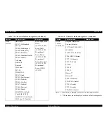
Page 8: ...C H A P T E R 1 PRODUCT DESCRIPTION ...

Page 9: ...version 13 tables NLSP version 42 tables Input buffer 128 Kbytes Acoustic noise 58 dB A ISO 7779 pattern Reliability MVBF Mean print Volume Between Failures except print head 1 3 billion lines MTBF 25 duty cycle MTBF 20 000 POH Print head life 200 million strokes wire approx 400 million characters Draft 10 cpi 14 dots character Ribbon life 15 million characters Draft 10 cpi 14 dots character Inter...

Page 10: ...t also can be selected Auto paper change Paper source change Rear Tractor Front Tractor from software or the control panel Paper jam detection Detects paper jams and indicates the error status 1 1 1 1 External view and part names Figure 1 1 External View Front Top Cover Paper Separator Cover Print Head Front Tractor Power Switch Card Guide Front Cover Control Panel ...

Page 11: ...s and options Name Epson Product Code Consumables Ribbon cartridge black S015384 Options Pull tractor unit C12C800381 Perforation cutter C815071 Serial I F card C823051 32 KB intelligent serial I F card C823071 Local Talk I F card C823121 Coax I F card C823141 Twinax I F card C823151 EpsonNet 10 100 Base Tx internal print servers C12C823912 C12C824341 EpsonNet 802 11b g wireless external print ser...

Page 12: ...rms Dimension W D H 700 378 363 mm 27 6 14 9 14 3 inches 700 382 369 mm 27 6 15 0 14 5 inches Weight 34 0 kg 74 8 lbs 29 0 kg 63 8 lbs Interface Std IEEE 1284 Bi D Serial RS232C USB 1 1 Optional Type B slot 1 Std IEEE 1284 Bi D Serial RS232C Optional Type B slot 1 Buffer Memory 128 KB 128 KB Reliability MTBF 20 000 POH MTBF 10 000 POH Life Printhead 400 million characters 200 million strokes wire ...

Page 13: ...int High Speed Draft 10 cpi 90 dpi 72 dpi No High Speed Draft 12 cpi 96 dpi 72 dpi No Draft 120 dpi 72 dpi No Draft condensed 240 dpi 72 dpi No Draft emphasized 120 dpi 72 dpi Yes NLQ 240 dpi 144 dpi No Bit Image 60 72 80 90 or 120 dpi 72 dpi Yes 120 or 240 dpi 72 dpi No Table 1 4 Print speed and printable columns Printing mode Character pitch cpi Printable columns Printing speed cps 1 Normal mode...

Page 14: ...ont or rear Feeder Front push tractor Rear push tractor Pull tractor option Paper path Front or rear in top out Line spacing 4 23 mm 1 6 inch or programmable in increments of 0 059 mm 1 432 inch Feed speed Normal mode 4 23 mm 1 6 inch feed 25 ms Continuous feed 0 381 m sec 15 0 inches sec Copy mode 4 23 mm 1 6 inch feed 25 ms Continuous feed 0 279 m sec 11 0 inches sec 1 2 1 2 Input data buffer 12...

Page 15: ... 60H 7BH 7CH 7DH 7EH Bar code EAN 13 EAN 8 Interleaved 2 of 5 UPC A UPC E Code 39 Code 128 POSTNET Coda bar NW 7 Industrial 2 of 5 Matrix 2 of 5 Table 1 5 Character tables and typefaces Version Character table Bitmap font Standard version Italic table PC437 US Standard Europe PC850 Multilingual PC860 Portuguese PC861 Icelandic PC863 Canadian French PC865 Nordic Abicomp BRASCII Roman 8 ISO Latin 1 ...

Page 16: ...MAZOWIA Poland Code MJK CSFR ISO 8859 7 Latin Greek ISO Latin 1T Turkish Epson High speed Draft 10 CPI 12 CPI Epson Draft 10 CPI 12 CPI Proportional Epson Roman 10 CPI 12 CPI Proportional Epson Sans Serif 10 CPI 12 CPI Proportional Epson OCR B 10 CPI Table 1 5 Character tables and typefaces continued Version Character table Bitmap font NLSP version Continued Bulgaria Bulgarian Estonia Estonia PC 7...

Page 17: ...n using the Manual Platen Gap mode the platen gap must be set to the proper position as shown below This setting is for customization only Table 1 6 Platen Gap Setting and Paper Thickness SelecType setting Paper thickness inch Paper thickness mm Platen gap mm Min Max Auto 0 0028 0 0311 0 07 up to 0 79 0 39 to 1 09 0 0 0003 Under 0 08 0 39 1 0 0035 0 0051 0 09 up to 0 13 0 44 2 0 0055 0 0071 0 14 u...

Page 18: ...61 Letter pattern Approx 9 5 W in sleep mode 0 W in powered off mode Energy Star Compliant Dielectric strength AC 1500 Vrms 1 sec between AC line and chassis The printer enters sleep mode after 5 minutes of inactivity if both of the following are true The printer is not in an error condition There is no data in the input buffer 1 2 3 Safety approvals Safety standards UL60950 CSA C22 2 No 60950 EN6...

Page 19: ...nvironment conditions Operating Temperature 5 to 35 C 15 to 25 C when printing labels continuous forms with labels and overlapping continuous forms Humidity 10 to 80 RH non condensing 30 to 60 RH non condensing when printing labels continuous forms with labels and overlapping continuous forms Shock Resistance 1 G within 1 ms Vibration Resistance 0 25 G 10 to 55 Hz Non operating Temperature 30 to 6...

Page 20: ...aper multipart Table 1 7 Continuous form single sheet paper specifications front or rear paper path Item Tractor Tractor Cutter Min Max Min Max Width mm 76 2 419 1 101 6 406 4 inch 3 16 5 4 16 Length one page mm 76 2 558 8 101 6 431 8 inch 3 22 4 17 Total thickness mm 0 065 0 1 0 065 0 1 inch 0 0025 0 0039 0 0025 0 0039 Weight single sheet g m2 52 82 52 82 lb 14 22 14 22 Table 1 8 Multipart paper ...

Page 21: ...use the table below find the column that represents the total number of sheets in your multipart form The rows in the column indicate the maximum weight for each sheet in the form in grams per square meter g m2 Item Tractor only Tractor and Cutter Min Max Min Max Width mm 76 2 419 1 101 6 406 4 inch 3 16 5 4 16 Length one page mm 76 2 558 8 101 6 431 8 inch 3 22 4 17 Copies 1 original 9 copies 1 o...

Page 22: ... are joined with metal staples one sided crimping tape staples or bar gluing Less than 25 4 mm 1 inch Less than 25 4 mm 1 inch Less than 76 2 mm 3 inch The thickness of the crimped part when extended should be less than 0 9 mm Less than 25 4 mm 1 inch Less than 76 2 mm 3 inch Printing Side Non printing Side The thickness of the crimped part when extended should be less than 0 9 mm The any crimp de...

Page 23: ...ength of the perforation should be between 2 1 and 5 1 The space between horizontal perforation cuts and paper edge should be more than 1 mm If a vertical line and horizontal line are crossed at the cut parts a the area shown in the figure below will be the unprintable area If crossed at the uncut parts b the printable area will not be limited 3 mm 28 mm Cross Part Uncut a b Cross Part Cut 28 mm 3...

Page 24: ...thickness platen gap is measured on the label or use the appropriate manual setting 8 Do not print labels when the Perforation Cutter is installed Labels and base sheet type Figure 1 10 Base sheets entirely covered with label material Figure 1 11 Base sheets not covered with label material Table 1 11 Label specifications front or rear paper path Item Min Max Label size Refer to Figures 1 10 and 1 ...

Page 25: ...er is installed Figure 1 12 Continuous forms with labels Figure 1 13 A sheet composed of continuous paper and labels paper Table 1 12 Item Rear paper path Front paper path Min Max Min Max Base sheet width mm 76 2 419 1 76 2 419 1 inch 3 16 5 3 16 5 Base sheet length mm 76 2 558 8 76 2 558 8 inch 3 22 3 22 Total thickness mm 0 065 0 53 0 065 0 79 inch 0 0025 0 021 0 0025 0 031 Base Sheet Label Less...

Page 26: ...h Front paper path Min Max Min Max Base sheet width mm 76 2 419 1 76 2 419 1 inch 3 16 5 3 16 5 Base sheet length mm 76 2 558 8 76 2 558 8 inch 3 22 3 22 Total thickness mm 0 13 0 53 0 13 0 79 inch 0 0051 0 021 0 0051 0 031 Cut Sheet Multipart Base Sheet Glue Point Area Perforation Glue Point Area More than 3 3 mm From the perforation to the top of the next overlapping form Less than 17 mm From th...

Page 27: ...ble 1 14 Printable area for continuous paper Item Continuous paper PW width Refer to sections 1 2 6 1 Continuous paper single sheet p 13 and 1 2 6 2 Continuous paper multipart p 13 PL length LM left margin 13 mm or more when the paper width is at least 127 mm 5 inches 10 mm or more when using the Pull Tractor RM right margin 13 mm or more TM top margin 4 2 mm or more BM bottom margin 4 2 mm or mor...

Page 28: ...us labels Parameter Specifications PW width Refer to 1 2 6 3 Labels p 17 PL length LM left margin 13 mm or more when the paper width is 127 mm 5 inches 10 mm or more when using the Pull Tractor RM right margin 13 mm or more TM top margin 2 2 mm or more LOL left margin on label 3 mm or more ROL right margin on label 3 mm or more TOL top margin on label 2 mm or more BOL bottom margin on label 2 mm o...

Page 29: ...ion PW width Refer to 1 2 6 4 Continuous forms with labels p 18 PL length LM left margin 13 mm or more when the paper width is 127 mm 5 inches 10 mm or more when using the Pull Tractor RM right margin 13 mm or more TM top margin 4 2 mm or more BM bottom margin 4 2 mm or more LFL left margin from label 30 9 mm or more RFL right margin from label 30 9 mm or more TFL top margin from label 20 2 mm or ...

Page 30: ...ntable Area PW LM RM Base Sheet Cut Sheet TM1 TM2 BM PL Perforation Table 1 17 Printable area for overlapping multipart forms Item Labels paper PW width Refer to 1 2 6 5 Overlapping multipart forms p 19 PL length LM left margin 16 mm or more RM right margin 16 mm or more TM1 top margin 26 3 mm or more TM2 top margin 26 3 mm or more starting on page 2 BM Bottom margin 16 6 mm or more ...

Page 31: ... is off and 3 0 V or higher when the printer is on The receiver has an impedance equivalent to 7 5 kΩ Data transmission timing Figure 1 19 Data transmission timing Notes 1 Rise and fall time of output signals 2 Rise and fall time of input signals Table 1 18 Parameters Parameter Minimum Maximum Condition VOH 5 5 V VOL 0 5 V IOH 0 32 mA VOH 2 4 V IOL 12 mA VOL 0 4 V CO 50 pF VIH 2 0 V VIL 0 8 V IIH ...

Page 32: ... there is a cover open error When there is a paper jam error When there is a ribbon out error When there is an incomplete paper change error The PE signal is active high when there is a paper out error Table 1 20 Connector pin assignment forward channel Pin No Signal name Return GND Pin In Out Function description 1 STROBE 19 In This signal is a strobe pulse Input data is latched at the falling ed...

Page 33: ... the printer is powered on 14 AFXT 30 In Not used 31 INIT 30 In This signal s negative pulse initializes the printer 32 ERROR 29 Out This signal is low when the printer has error 36 SLIN 30 In Not used 18 Logic H Out This line is pulled up to 5 V through a 3 9 kΩ resistor 35 5 V Out This line is pulled up to 5 V through a 1 0 kΩ resistor 17 Chassis Chassis GND 16 33 19 30 GND Signal GND 15 34 NC N...

Page 34: ...tive when the request is 00h or 04h 00h Request nibble mode of reverse channel transfer 04h Request device ID in nibble mode of reverse channel transfer Device ID The printer sends the following device ID strings when it is requested When IEEE 1284 4 is enabled 00h 50h MFG EPSON CMD ESCP9 PRPII9 BDC D4 MDL DFX 9000 CLS PRINTER DES EPSON SP DFX 9000 When IEEE 1284 4 is disabled 00h 4Dh MFG EPSON CM...

Page 35: ...e channel transfer data bit 2 or 6 13 Xflag DataBit 1 5 28 Out X flag signal and reverse channel transfer data bit 1 or 5 14 HostBusy 30 In Host busy signal 31 INIT 30 In Not used 32 DataAvail DataBit 0 4 29 Out Data available signal and reverse channel transfer data bit 0 or 4 36 1284 Active 30 In 1284 active signal 18 Logic H Out This line is pulled up to 5 V through a 3 9 kΩ resistor 35 5 V Out...

Page 36: ...nput buffer is 256 bytes The DTR signal is SPACE and the XON code DC1 11h is transmitted as soon as the available space in the input buffer exceeds 256 bytes Error handling Only parity errors are detected Overrun and framing errors are ignored Connector 25 pin subminiature D shell connector female In Out refers to the signal flow direction from the printer s point of view Table 1 22 Connector pin ...

Page 37: ...m error During a ribbon jam error During a ribbon out error During a paper out error During an incomplete paper change error The USB responds to a BULK OUT transaction with NAK and BULK IN transaction with NAK under the following conditions When the input buffer is full During hardware initialization In the self test mode In the adjustment mode When there is a printer hardware error fatal error th...

Page 38: ...MD ESCP9 PRPII9 BDC D4 MDL DFX 9000 CLS PRINTER DES EPSON SP DFX 9000 When IEEE 1284 4 is disabled 00h 4Dh MFG EPSON CMD ESCP9 PRPII9 BDC MDL DFX 9000 CLS PRINTER DES EPSON SP DFX 9000 SOFT RESET This USB Device Request is used when the Host initializes the printer s input buffer Table 1 24 GET PORT STATUS reply specification Bit Field Field 7 6 Reserved Reserved 5 Paper Empty 0 Paper Not Empty 1 ...

Page 39: ...h Start Software Reset Init signal on the std Parallel Type B I F Option command 01h Panel Reset Cold start 02h Send Option Type Determines the level of Type B I F after powered on 04h Send Name Data Type B I F Option command 05h 07h Inquire Software Emulation Type Changing control language 0Eh Inquire ASCII Message Writing to DBIN register 14h Inquire Emergency Reply Reply for background job comm...

Page 40: ...uire Name Data Accept Execute OK 06h Send Product Name Accept See 2 Table 1 27 See 2 Table 1 27 Execute OK 07h Send Software Emulation Type Accept See 3 Table 1 27 See 3 Table 1 27 Execute OK 08h Complete Buffered Data Accept Execute OK 09h Stop Procedure Reject 0Ah Return Buffered Data Reject 0Bh Send Entity Type Accept See 4 Table 1 27 See 4 Table 1 27 Execute OK 0Ch Send Status Accept See Table...

Page 41: ...ork Settings Accept 0000h Execute OK 18h 1Fh Reserved N A Table 1 27 Major optional command OPCMD replies Level 2 Type B interface OPCMD Reply Message ESC P IBM PPDS 1 03h Main Type MT9p PW136cl10cpi PRG Wxxxxxxx rev AP500ma MT9p PW136cl10cpi PRG Wxxxxxxx rev AP500ma 2 06h Product Name DFX 9000 DFX 9000 3 07h Emulation Type ESCP9 PRPII9 BDC ESCP9 PRPII9 BDC 4 0Bh Entity Type EPSONFX EPSONPRPII9 Ta...

Page 42: ...0 0 0 1 Paper Jam Error Paper Jam Error Printer Error Paper SP Jam 0 0 0 0 1 0 1 Ribbon Jam Error Expanded Error Printer Error Expanded SP Error 1 0 0 0 0 0 1 Ink or Ribbon End Error Expanded Error Printer Error Expanded SP Error 1 0 0 0 0 0 1 Paper Out Error Paper Out Error Printer Error Paper SP Out 0 0 0 0 0 1 1 Setting Mode Setting Mode Printer Error SelecType 0 0 0 0 0 0 1 Expanded Error Expa...

Page 43: ...ith the Simplified Serial I F Card 19200 9600 4800 2400 1200 600 300 Table 1 29 Supplemental printer information returned for 06h with 02h 03h Printer s information ST status code ER error code TP self print code PP paper path CD characteristic status codes IG nn1 nn2 nn3 nnx1 nnx2 nnx3 TEC ii1 FF Table 1 30 Background job commands BGJC BGJC number Command Response 0x00 Get device ID Device ID Nor...

Page 44: ... serial interface card is installed and it is not selected the interface sends XOFF and sets the DTR signal to MARK When the optional interface is not selected the printer sets the OFFLINE bit of the MNSTS register to the optional interface When the printer is initialized or returned to the idle state the parallel interface enters a ready state the USB interface is ready to respond to an OUT trans...

Page 45: ...ceived communication in IEEE 1284 4 packet mode starts Off Communication is carried out in the conventional mode When printing from a Windows based printer driver set the packet protocol to Auto The functionality of the Off mode in IEEE 1284 4 protocol is not guaranteed on the USB I F NOTE The packet protocol of IEEE 1284 4 allows a device to carry on multiple exchanges or conversations that conta...

Page 46: ... with 9 switches 6 LEDs and 1 LCD 16 characters 2 line which are located as shown below 1 3 1 1 Buttons The following table explains the button functions Some buttons perform multiple operations Figure 1 21 Control Panel buttons and LEDs Pause Micro Feed LF FF Load Top of Form Tear Off Pitch Font Front Rear Micro Feed Pause LED Tear Off LED Top of Form LED Front LED Rear LED LCD Paper Out LED ...

Page 47: ...ver is open Enters the Top of Form Adjustment mode when you press it Enters the Paper Loading Adjustment mode when pressed immediately after loading paper NLQ self test Changes the setting Tear Off Set Advances continuous paper to the Tear off position Changes the setting Pitch Item Selects the font pitch Selects pitch Selects the menu Font Item Selects the font and draft quality Default setting m...

Page 48: ... Pause Micro Feed LF FF Load Clears the EEPROM See Clear EEPROM p 51 Pitch Font Front Rear Error analysis mode See Error analysis mode acquire EEPROM information p 52 Table 1 31 Summary of button functions Button Function Normal mode At power on SelecType mode ...

Page 49: ...en LED turns on when the front paper path is selected and paper is loaded in the front tractors Red LED turns on when the front paper path is selected but no paper is loaded in the front tractors Turns off when the rear paper path is selected Rear Green Red Green LED turns on when the rear paper path is selected and paper is loaded in the rear tractors Red LED turns on when the rear paper path is ...

Page 50: ...r Ribbon jam 5 Ink ribbon out error Error Ribbon out 6 Paper out error Error Paper out 7 Paper out error Loading Error No paper loaded 8 Incomplete paper path change Error Switching not completed 9 Print head is overheated Print head hot Please wait 10 The entry to SelecType and Default setting mode Setting mode 11 Panel lock out2 Locked 12 Top of Form Loading position 3 Loading position adjustmen...

Page 51: ...nting Top of Form position Micro Feed Adjusts the paper position for Top of Form and Tear Off The Micro Feed button advances the paper forward by 0 118 mm 1 216 inch and the Micro Feed button advances the paper backwards by 0 118mm 1 216 inch The TOF just after loading adjustment range is 4 2 to 33 9 mm The default setting is 8 5 mm Default The buzzer sounds at the minimum default and maximum posi...

Page 52: ...d again this mode is terminated The adjusted position is stored as the Tear Off position in non volatile memory and the paper is fed back to its previous position Pitch Press this button to select one of the following pitches 10 cpi factory default 12 cpi 15 cpi 17 cpi 20 cpi Proportional Font Pressing this button selects one of the following fonts High speed draft factory default Draft Roman Sans...

Page 53: ...on or exit SelecType mode 9 When you finish reviewing or changing the settings press the Menu Tear Off Top of Form button 10 The LCD displays Save Setting If you wish to save the settings select Yes by pressing the Set Tear Off button If you do not want to save the settings select No by pressing the Set Top of Form button 11 The printer exits SelecType mode C H E C K P O I N T The language you sel...

Page 54: ...arallel Bi D On Packet mode Auto Baud rate 19200 BPS Parity None Data length 8 bit Character table PC437 Auto CR IBM Off IBM table Table 2 Buzzer On Low noise mode Off Auto cut mode Off Auto cut back Off Overlapping forms Off Forms w labels Off Skip binding Off Get IP address Panel IP byte 1 000 000 000 000 IP byte 2 000 000 000 000 IP byte 3 000 000 000 000 IP byte 4 000 000 000 000 SM byte 1 000...

Page 55: ...direction Bi D Uni D Software ESC P IBM PPDS Others1 0 slash Off On I F mode Auto Parallel Serial USB Optional I F wait time 10 seconds 30 seconds Parallel Bi D Off On Packet mode Auto Off Baud rate 19200 BPS 9600 BPS 4800 BPS 2400 BPS 1200 BPS 600 BPS 300 BPS Parity None Odd Even Ignore Data length 8 bit 7 bit Character table STD version PC437 PC850 PC860 PC863 PC865 PC861 BRASCII Abicomp Roman8 ...

Page 56: ... labels Off On Skip binding Off On Get IP address3 Panel Auto PING IP byte 14 000 000 000 000 to 255 255 255 255 IP byte 24 000 000 000 000 to 255 255 255 255 IP byte 34 000 000 000 000 to 255 255 255 255 IP byte 44 000 000 000 000 to 255 255 255 255 SM byte 13 000 000 000 000 to 255 255 255 255 SM byte 23 000 000 000 000 to 255 255 255 255 SM byte 33 000 000 000 000 to 255 255 255 255 SM byte 43 ...

Page 57: ...the Pause button 2 The printer prints the adjustment instructions and the first alignment pattern 3 Select the most closely aligned pattern number using the Item Font or Item Pitch buttons to scroll through the selection numbers The LCD shows the pattern number currently selected 4 Select the best pattern number by pressing the Set Top of Form button That pattern number is saved and the next align...

Page 58: ... To turn off the panel lock out mode repeat steps 1 and 2 The printer beeps once indicating that the panel lock out mode has been turned off The table below shows the available custom lockout settings with the factory default settings underlined Notes 1 If Unlock is selected the switch function is enabled whether Panel Lock Out mode is on or off 2 If Lock is selected the switch function is disable...

Page 59: ...in an error state To enable Error Analysis mode turn the power on while holding down the Front and Pitch buttons The printer beeps once and enters IEEE 1284 4 Protocol mode NOTE The printer forcibly enters IEEE 1284 4 packet mode even if a fatal error has occurred and communication with the PC becomes available This mode is used with the Adjustment Program to get information from the printer when ...

Page 60: ...ption Dimensions and weight 53 1 4 Dimensions and weight Physical specifications Dimensions 700 mm W 378 mm D 363 mm H 27 5 inches 14 9 inches 14 3 inches Weight 34 kg 75 lbs Appearance See the figure below Figure 1 23 Physical specifications ...

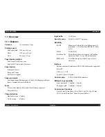
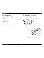
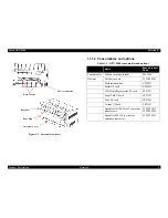
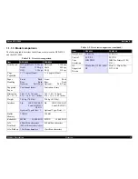
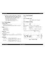
Page 61: ...Epson DFX 9000 Revision B Product Description Dimensions and weight 54 ...

Page 62: ...C H A P T E R 2 OPERATING PRINCIPLES ...

Page 63: ...rol board Power unit Power supply board OP board Operation panel board Printer mechanism Print Head Carrier mechanism Ribbon mechanism Paper feed mechanism APTC mechanism Figure 2 1 Main Components ROM Board Printer Mechanism Power Unit OP Board Others APTC Mechanism Paper Feed Mechanism Ribbon Mechanism Carrier Mechanism Print Head ...

Page 64: ...ower to the SP Motor SP Belt CR Belt The drive belt that moves the Carrier LF Motor LF Belt PF Motor PF Belt Paper feed motor Paper feed drive belt APTC APTC Motor Platen gap adjustment mechanism APTC Automatic Paper Thickness Control HCPP motor sensor etc Tractor select mechanism Host Computer controlled Paper Path HCPP The paper path front rear switching mechanism controllable through the print ...

Page 65: ...hanism p 75 2 2 6 2 Cooling fans p 76 2 2 1 Printhead The printhead contains 36 coils that drive armatures to which the print wires are attached When not firing the armatures are pushed back to the stopper by coil springs When the coil is energized the armatures attracted by the magnetic field move the print wires in the direction of the red arrow below in Figure 2 2 The print wires guided by the ...

Page 66: ...numbers 3 and 4 comprise the Rear head inner pins in the matrix and head numbers 1 and 2 comprise the Front head outer pins The thirty six print wires are arranged in a diamond shape as shown in Figure 2 3 which also shows the pin out matrix of the four printheads Figure 2 3 The pin out of the four print heads Front Sub Head Rear Pin Group 1 4 3 2 Each Pin Group consists of 9 pins Pin 1 Pin 1 Pin ...

Page 67: ...stops and then resumes at half the normal print speed Thermal protection When temperatures detected by the thermal sensors on the front and rear of the printhead are substantially different from each other printing is paused or stopped The following processes are performed when the thermal sensors detect an abnormally high temperature level 1 If the printhead temperature reaches114 C the printer w...

Page 68: ...ed by both the Carriage shaft and Guide stay The Shield plate on the left side of the Guide Stay is used to detect a horizontal reference position for the Carrier unit When printing the position of the Carrier unit is determined by the CES scale and the CES sensor on the Carrier unit with reference to the print start position and the motor speed The resolution of the CES scale is 1 120 inch Figure...

Page 69: ...cts the Shield plate when the sensor is not in position to do so The out of step detection is not carried out each carriage pass It is performed whenever the Carrier unit passes over the Shield Plate while printing or during other normal carriage operations CR motor driver error The CR motor driver error fatal error CR driver error occurs under the following conditions When a damaged SP motor or d...

Page 70: ...detects the rotation of the RF shaft directly engaged to the driven roller inside the ribbon cartridge If a ribbon stops feeding the RFS sensor detects that the RF shaft has stopped Printing stops and a Ribbon Jam error message is displayed on the control panel LCD Ribbon installation detection The Ribbon Mechanical Switch RMS switch is pressed down when a ribbon cartridge is installed If the swit...

Page 71: ...r DV rollers as shown in the flow chart below Figure 2 7 Tractor Mechanism LF Motor Pulley Gear Shift Gear TR Gear 1 Front Tractor TR Gear 2 RTR Intermediate Gear RTR Intermediate Gear TR Gear 3 Rear Tractor DV Gear F Nip Gear F DV Roller F DV Gear R1 DV Gear R2 Nip Gear R3 Nip Gear R4 DV Roller R DV Gear R1 DV Roller R LF Belt RTRIntermediate Gear Left Side Frame TR Gear 3 Tension Pulley Nip Gear...

Page 72: ...ller Continuing upward it is fed across the Platen and directed by the Card guide on the Carrier unit After the form has passed the Card guide it is transported and ejected by the Paper eject unit The Pin belt tractors DV roller F and Paper eject unit are all driven by the LF motor Figure 2 8 Continuous Business Form Feed Platen DV Roller F LF Motor Platen DV Roller F Rear Tractor Continuous form ...

Page 73: ...nsors on the Card guide and Paper eject unit Paper sensor The photo sensors on the tractors are shielded or unshielded by the movement of the sensor lever If paper is not loaded the sensor lever shields the sensor to indicate that paper is not set on the tractor Figure 2 9 Paper detection 1 Sensor Lever Front tractor Photo Sensor Sensor Lever Rear Tractor Photo Sensor ...

Page 74: ...edges of paper when it is loaded Paper jam detection Paper travel is detected by the magnet roller and the Hall IC PJS located on the 1st Nip Roller When the Hall IC detects an abnormal rotation of the magnet roller line feed and then printing stop and the control panel LCD displays the message Error Paper jam Remove the jammed paper and press PAUSE to clear the error Figure 2 10 Paper detection 2...

Page 75: ... Card guide Figure 2 11 Auto paper feed Tractor feed mechanism error detection An error in the tractor feed mechanism is detected by the PF driver Fatal error PF driver error under the following conditions When a damaged LF motor or defective LF motor driver causes an abnormal electric current When a single phase of the LF motor is energized for longer than the allowable time The 42 V power supply...

Page 76: ...otor drive system is unipolar and constant current Figure 2 12 Paper path switching mechanism Paper path switching mechanism error detection Paper path switching mechanism errors are detected by the HCPP motor driver The error Fatal error HPCC driver error is detected when a single phase of the HCPP motor is energized for longer than the allowed period of time The 42 V power supply is shut off by ...

Page 77: ...d by a condition 2 event when the Carrier unit to moves to the ribbon replacement position the rollers will return to the prior condition 1 or 3 the next time the Carrier unit moves 2 The Carrier unit moves to the ribbon replacement position under the following conditions When the power is turned ON When the printer is in PAUSE After the printer is reset Three seconds after entering an idle state ...

Page 78: ...by the Open Close OC motor driver The error Fatal error OC driver error is detected when a single phase of the OC motor is energized for longer than the allowed period of time The 42 V power supply is shut off when this error is detected An OC motor out of step error cannot be detected because the mechanism does not include a circuit to detect motor rotations ...

Page 79: ...aft to move the Carrier unit Printhead away from the paper contact position 2 The APTC Home Position HP sensor detects that the Carrier unit reaches the furthest position by checking the phase of the SS Gear 3 The Carrier unit is then moved back toward the paper by the APTC motor until the APTC sensor detects a change in the APTC motor load caused by contact with the paper 4 The printhead to paper...

Page 80: ...C mechanism The media gap is a calculated space using a predefined formula based on the paper thickness value Figure 2 15 Platen gap components Figure 2 16 shows how the printer measures the paper thickness with the APTC mechanism The printer counts the number of drive pulses applied to the APTC Motor while monitoring the width of time between the pulses output from the APTC Sensor encoder A chang...

Page 81: ...C HP sensor is ON Load paper and feed to a predefined position Rotate APTC Motor counter clockwise Check pulse count and width with APTC Sensor Media surface position Pulse Count when the pulse width changes widens or narrows Rotate APTC Motor clockwise total number of steps Paper Thickness Media Gap Paper Thickness Platen Count Paper Count Paper Count Calculate Media Gap using predefined formula ...

Page 82: ... Open switches can be bypassed as explained in the table below if the unit is needs to be operated with the top cover or upper housing removed W A R N I N G Exercise extreme care when working on the unit with these safety switches bypassed The SP motor is enabled and the Carrier unit moves at very fast speed If the Carrier unit strikes you at high speed it could result in injury Table 2 5 Bypassin...

Page 83: ...ing too high Each of the fan motors has a rotation detection sensor that outputs a pulse signal If a fan is not rotating the output signal stops cycling and the signal stays either High or Low When the controller detects this condition it shuts off the 42 V supply and all fan motors and printing operations stop Figure 2 19 Cooling Fan FAN1 Motor FAN2 Motor FAN3 Motor FAN4 Motor Left Side Frame Rig...

Page 84: ...D display Operator switches Power Unit 42 V 37 V and 5 V supply Host computer Parallel serial USB Type B Main control circuit 3 3 V voltage generation retention circuit Motor drive circuits Head drive circuit Interface circuit LCD LED display Operator switches 42 V SG3 37 V SG2 5 V SG1 ROM Board Power Unit OP Board USB Interface SP Motor LF Motor Carrier Unit Carrier PCB OP Board Sensor Board Unit...

Page 85: ...lowing functions I O control all I F ports Memory management Print data processing Figure 2 22 Circuit Block Diagram 3 3 V XPST42V Power Unit OP Board LCD LED SW SoC ASIC D RAM 16MB Head Driver Motor Driver Motor Safety Circuit Head Safety Circuit 3 3 V Regulator 3 3 V Protect Circuit Reset Circuit Flash Memory 4MB FRAM 4K Parallel Interface Serial Interface USB Interface Type B Interface 42 V ASI...

Page 86: ...ertor and 8 KB of RAM Figure 2 23 SoC ASIC internal block diagram Location Name Function summary LSI1 SiX55513 SoC ASIC ASIC coupled with CPU Memory control I O Control External I F ports IC1 MBM29LV160 Flash memory 16 MB IC3 MSM51V18165F D RAM 16 MB IC9 74VHC161284MTD IEEE 1284 Bi directional communication control IC IC11 MAX3243 Serial port driver IC LSI2 MB87L5090 Mechanism Control ASIC printer...

Page 87: ...tialize BMU Bit Manipulation unit This module processes the print data and modifies it for specific printing modes enlarge Italicize Super Sub Script conversion etc IOU I O Control Unit IBCU The Input Buffer Control unit controls the input buffer pointer address R W and the buffer size USB USB I F 1 1 Full speed device compliant Control unit PIFU IEEE 1284 Parallel I F Control unit TYPEBIFU Type B...

Page 88: ...nd character generator data D RAM 16 Mbit of DRAM are used as the work area for data processing and print image data generation F RAM 4 Kbit of F RAM are used to store mechanical adjustment parameters and operational history information error log print operation log etc The CPU communicates with this chip through a two line serial interface Data signal Clock signal Figure 2 24 Memory control circu...

Page 89: ...on X42VPST X37VPST control section MOTOR control section HEAD DRIVE control section Interrupt signal control section FAN alarm control section MOTOR alarm control section 8 bit A D control section CR ENC control section APTC ENC control section CLOCK control section CR MOTOR control section A 1 9 XCE7 XRD XWRL D 0 15 M_FTPE M_RTPE M_PPSS M_OCS1 M_OCS2 M_PJS M_APTC M_RFS M_RMS M_PTRM M_LES M_PCHPS ...

Page 90: ...gnal is high the motor stops driving M_BRAKE is a brake input signal When the signal is low the motor is braked When the signal is high the motor rotates normally PWMIN is a pulse input signal M_TIM1 and its output is controlled based on the duty levels When the signal input is low the pulse output turns ON When the input is high the pulse output turns OFF UH UV UW are PWM output signals that are ...

Page 91: ...turns ON when the output is High Z causing current to be applied to the motor The motor current passes through the resistance detection section At the same time the voltage applied to the detection section is compared with the voltage generated in the reference voltage section of the LF motor driver internal circuit If the applied voltage exceeds the reference voltage a logic operation AND is perf...

Page 92: ...TC motor and OC motor are PM stepping motors The position control of these motors is achieved using paper sensor pulse counts and speed is controlled using excited cycle and open loop controls A general purpose transistor array provides the control logic The three motors are constant voltage motors and their drive circuits have identical configuration The following figure shows a block diagram of ...

Page 93: ... exceeded the power line is shut off by the fuse LF motor RF motor HCPP motor and APTC motor When an abnormal current that exceeds the prescribed level is detected the status is sent to the Mechanism Control ASIC If the Mechanism Control ASIC detects that the status has continued for a certain period of time the 42 V 37 V line for the ROM board is cut off by turning the X42VPST signal to LOW The f...

Page 94: ...m Control ASIC Figure 2 34 Printhead Control Block Diagram SoC ASIC ASIC Printhead ROM Board Power Unit Printhead Control Section Flyback absorption circuit Safety Check Control Section Safety Check Detection Section D0 15 HDIRQ A1 9 FB_01 36 PD01 PD02 FR2 FR1 FR9 GND PD36 42V DIN00 15 PD01 09 PD11 19 PD21 29 PD31 39 FB01 09 FB11 19 FB21 29 FB31 39 HD_IRQ 42 V Voltage CR Linear Encoder_A CR Linear...

Page 95: ... the firmware The following shows the print trigger generation timing Figure 2 35 Print trigger generation timing Since the CR encoder resolution is 1 120 inch some print densities do not match the resolution of the CR encoder input In those cases the print timing is calculated based on the last CR encoder cycle The print density supports 480 360 240 180 144 2880 21 120 96 90 80 72 and 60 dpi Prin...

Page 96: ...time The Mechanism Control ASIC then outputs a main excitation control signal MAINF_xx and flyback signal FLYBK_xx to activate the transistor to control the printhead Head abnormal current detection circuit When an abnormal current exceeding the prescribed level is detected the status is sent to the Mechanism Control ASIC If the Mechanism Control ASIC internal circuit detects that the status has c...

Page 97: ...during power down at AC OFF by detecting a signal from the AC presence absence detection circuit 42V converter section This section consists of a forward choke converter FCC that uses a switching control IC and has the following functions 42 V 37 V ON OFF control The 42 37 V circuit ON OFF is controlled using the 42VST signal The 42 37 V is ON when 42VST is low and shuts off when 42VST is high Ove...

Page 98: ...wer has been switched off this circuit switches the voltage to a charged electric double layer condenser At the same time the circuit extends the 3 3 V output time by switching the input voltage for the regulator section where 3 3 V has been generated providing a minimum of 50 ms of time to allow data writing for FRAM and the XOFF response of the serial interface The following shows a block diagra...

Page 99: ...Epson DFX 9000 Revision B Operating Principles Circuit operation 92 ...

Page 100: ...C H A P T E R 3 TROUBLESHOOTING ...

Page 101: ...specified tools to avoid impairing the quality of the printer When troubleshooting motors always check the driver circuit as well and vice versa A malfunction in one of these components can cause the other to fail and will cause the replacement part to fail as well Always check both the motor and driver Use only specified lubricants and adhesives Carry out any necessary adjustments by following th...

Page 102: ...it can be exposed to direct sunlight 8 The printer must be located in a well ventilated place 9 The printer must be placed on a strong steady and level less than 5 inclination surface 10 The paper used must conform to the specifications listed in Chapter 1 11 There must be no abuse or mishandling of the printer 12 The Periodic Maintenance Parts must be replaced on schedule See Chapter 6 Maintenanc...

Page 103: ...Epson DFX 9000 Revision B Troubleshooting Overview 96 3 1 3 Power on initialization sequence Main ...

Page 104: ...Epson DFX 9000 Revision B Troubleshooting Overview 97 Mechanism initialization e e e e e ...

Page 105: ...DFX 9000 Revision B Troubleshooting Overview 98 Mechanism initialization continued eration operation eration CR Centering operation to the center of Paper Width CR Centering operation to 35th column operation ...

Page 106: ...Epson DFX 9000 Revision B Troubleshooting Overview 99 Paper Backout Paper Ejection RTN from Tear Off state RTN from TOF Mark Position ...

Page 107: ...Epson DFX 9000 Revision B Troubleshooting Overview 100 PAPER FEEDING FF APG APPROACH ...

Page 108: ...ton Error No paper loaded On On Paper out error loading Continuous paper is not fed to the standby position Tear off the page at the perforation then press the LF FF Load button The printer feeds the paper to the standby position Error Paper out On On Paper out error No paper is loaded on the selected tractor Load paper on the selected tractor or select a different tractor by pressing the Front Re...

Page 109: ...n interval of 100 ms Error Cover open On Cover open error The printer top cover is open Close the top cover Fatal Error xx Turn off printer Blink Blink Blink Blink Blink Blink Fatal error The printer will not recover from the error even after turning the power back on Refer to 3 3 2 Troubleshooting based on error codes p 106 Table 3 1 List of General Error Beeper sounds see below LCD Message LED S...

Page 110: ...ror Page 107 08 Over Load Error Page 107 09 FAN1 Driver Error Page 108 0A FAN2 Driver Error Page 108 0B FAN3 Driver Error Page 108 0C FAN4 Driver Error Page 108 0D No Head Error Page 108 0E Head Driver Error Page 108 0F APTC Error Page 109 11 Ribbon Feed Driver Error Page 109 12 Ribbon Jam Error Page 109 13 HCPP Driver Error Page 110 14 HCPP Error Page 110 15 OC Driver Error Page 110 16 OC Error P...

Page 111: ... Motor 365 446 ohm Table 3 4 Sensors and switches test reference Sensor Type Logical state FTRPE Photo interrupt Low paper present RTRPE Photo interrupt Low paper present OCS1 OCS2 Photo interrupt Low closed TPE Photo reflective High paper present COS Microswitch Low cover closed INLK SW Microswitch Low cover closed LES Photo interrupt Low home position APTCHP Photo interrupt Low home position TOF...

Page 112: ...in L 7 pin 3 R 5 pin l 5 pin R 5 pin L 5 pin 4 R 3 pin L 3 in R 3 pin L 3 pin 5 R 1 pin L 1 pin R 1 pin L 1 pin 6 R 9 pin L 9 pin R 9 pin L 9 pin 7 42 V 42 V 42 V 42 V 8 42 V 42 V 42 V 42 V 9 42 V 42 V 42 V 42 V 10 42 V 42 V 42 V 42 V 11 42 V 42 V 42 V 42 V 12 42 V 42 V 42 V 42 V 13 42 V 42 V 42 V 42 V 14 42 V 42 V 42 V 42 V 15 42 V 42 V 42 V 42 V 16 L 2 pin R 8 pin L 2 pin L 8 pin 17 L 4 pin R 2 ...

Page 113: ...r Unit See 4 2 4 17 CARRIER UNIT p 191 3 Check and replace the ROM BOARD See 4 2 3 2 ROM BOARD p 137 Fatal Error Code 02 CR Driver Error The SP motor or driver circuit IC18 is malfunctioning The Mechanism Control ASIC has detected an abnormal current flow to the SP motor A single phase of the SP motor was energized for longer than the allowed period of time Either the SP motor driver or both have ...

Page 114: ...e Carrier Unit 3 Replace the ROM BOARD p 137 Fatal Error Code 06 High Volt Error The motor 42 V or head drive 37 V voltage rose above the allowable level This error indicates a power output problem or a voltage detection circuit failure Check and replace the following in the order below checking functionality at each step 1 POWER UNIT p 136 2 ROM BOARD p 137 Fatal Error Code 07 Low Volt Error The ...

Page 115: ...37 Fatal Error Code 0D No Head Error A check of the print head thermistor circuit during power on initialization determined that the PRINT HEAD is not installed This error is caused by the following The Print Head is not installed The Print Head built in thermistor element has failed The Carrier Cable is disconnected or damaged The Print Head temperature detection circuit has failed Check the foll...

Page 116: ...r was energized for longer than the allowed period of time Check both of the following and replace all malfunctioning parts 1 RF MOTOR p 163 2 ROM BOARD p 137 Fatal Error Code 12 Ribbon Jam Error This error is indicated when the Hall effect pulse signal of the ribbon jam sensor is not detected during Ribbon motor rotation Check for a ribbon jam and replace the ribbon cartridge if necessary If the ...

Page 117: ...37 Fatal Error Code 15 OC Driver Error This error occurs when the Mechanism Control ASIC detects that a single phase of the OC Motor was energized for longer than the allowed period of time This indicates a malfunction of either the HCPP motor or ROM Board driver circuitry TA10 STA485A or both 1 Check OC motor connector CNO C on the Sensor Board See Figure 4 10 on page 137 2 Check both the OC moto...

Page 118: ...r CNSEN2 on the ROM Board See Figure 4 10 on page 137 3 Replace the Perforation Cutter Unit or ROM BOARD p 137 or both Fatal Error Code 18 PC Error This error is indicated when the reference position is not detected in a perforation cutter operation Check the following in the order below Do not replace the PC Unit until the driver circuit on the ROM Board has been tested and you are sure it is fun...

Page 119: ...on the LCD Page 114 Printing related trouble The printer does not receive or does not print data sent from the host computer Page 115 The print results differ from the data sent from the host computer Page 115 The printer does not start printing Page 115 Some dots are missing or unnecessary dots are printed Page 116 The printout is spaced incorrectly Page 116 The printout appears dirty or there is...

Page 120: ...d Page 119 Rear feed continuous forms will not feed backward Page 119 Paper is not fed or ejected properly Page 120 Line spaces become narrow Page 120 The paper is fed skewed Page 120 Paper jams occur during paper feed Page 121 The paper paths switch just before printing starts Page 121 Control panel related trouble The lamps on the control panel OP Board light improperly Page 121 The switches on ...

Page 121: ... BOARD The Control Panel LEDs all light but stay on Initialize Page 51 or Replace the ROM BOARD p 137 Normal Control Panel LED operation all LEDs light briefly but only the Power LED stays lit The printer stops initialization after the Control Panel LEDs light Check the following in the order below testing functionality after each step 1 Make sure the top cover is closed 2 Check and if necessary r...

Page 122: ...he host computer 4 Replace the ROM BOARD p 137 The printer will not print a self test 1 Verify that the CARRIER CABLE UNIT p 189 is correctly connected to the PRINT HEAD and ROM BOARD 2 Replace the ROM BOARD p 137 The print results differ from the data sent from the host computer The printer prints the self test but does not correctly print data from the host computer 1 Make sure that the applicat...

Page 123: ...the PRINT HEAD 3 Replace the CARRIER CABLE UNIT p 189 4 Replace the PRINT HEAD p 152 5 Replace the ROM BOARD p 137 The printout is spaced incorrectly 1 Check that the APTC adjustment operates normally and that the paper thickness adjustment is properly set 2 Perform the Bi D adjustment p 250 3 Clean and lubricate the STAY SHAFT Carrier oil pads p 267 4 Clean or replace the CES SCALE p 159 5 Check ...

Page 124: ...stment p 227 the APTC thickness detection adjustment p 238 and the APTC detection position adjustment p 241 6 If you print on Overlapping Multipart Forms use SelecType on the Control Panel to change that setting to On 7 Check and replace the Auto Paper Thickness Control APTC UNIT p 169 The printout is faint or the printed characters have uneven upper or lower edges 1 Replace the Ribbon Cartridge i...

Page 125: ...e Platen gap setting SelecType p 10 5 The following adjustments affect the platen gap the Card guide mount position adjustment p 227 the APTC thickness detection adjustment p 238 and the APTC detection position adjustment p 241 6 A portion of the ribbon has reversed i e ink side in Check the ribbon for a reversed fold Replace the ribbon cartridge if necessary Ribbon jam frequently occurs or is fre...

Page 126: ...the application software settings if applicable 3 Use the Panel Buttons to adjust the automatic loading position See Top of Form p 45 4 Perform the TOF sensor sensitivity adjustment p 235 If the TOF sensor is defective replace the CARD GUIDE ASY p 153 5 If the paper feed position problem occurs with paper feed from the front check the FTRPE Front Tractor Paper Empty Sensor If the sensor has failed...

Page 127: ...he paper is within specifications See Paper specifications p 13 2 Check and if necessary replace the LF MOTOR p 161 3 Replace the POWER UNIT p 136 4 Replace the ROM BOARD p 137 The paper is fed skewed 1 Verify that the paper is within all specifications See 1 2 6 Paper specifications p 13 Make sure the paper is mounted correctly and evenly in the tractors 2 Use SelecType to change the settings for...

Page 128: ...adjustment p 238 and the APTC detection position adjustment p 241 5 Check the Paper Jam Sensor and if it is defective replace the PJS HOLDER ASY p 195 The paper paths switch just before printing starts Check the paper path setting in the printer driver Control Panel related failure Troubleshooting procedure The lamps on the control panel OP Board light improperly 1 Verify the OP CABLE connection b...

Page 129: ... 6 OP UNIT Removal p 134 and Figure 4 10 ROM BOARD Removal 1 p 137 3 If necessary replace the OP CABLE p 144 4 Cycle turn off and back on the printer s power and confirm the trouble symptom NOTE If the printer is producing abnormal odor or smoke do not turn the power back on until the source has been determined and the problem resolved 5 Check and replace the OP UNIT p 134 6 Check and replace the ...

Page 130: ...C H A P T E R 4 DISASSEMBLY AND ASSEMBLY ...

Page 131: ...ischarge Be careful with the Printhead when you handle it as it may be very hot right after printing Do not touch the heat sink attached to the switching FETs Q101 102 103 301 302 303 on the power supply board right after power off as it may be very hot C A U T I O N To maintain efficient printer operation take the precautions below Use only the recommended tools for maintenance work Use only the ...

Page 132: ...ll tools and instruments listed above are commercially available Table 4 1 Tool and Instrument List Name Specification Epson Part No Phillips screwdriver No 2 B743800200 Phillips screwdriver No 1 B743800100 Screwdriver Flat head Hex nut driver 5 mm B741700200 Tweezers B741000100 Round nose pliers B740400100 Thickness gauge B776702201 E Ring holder Size 6 B740800800 Cotton tape 10 mm 1 2 in wide Mu...

Page 133: ... such as screws and washers Table 4 2 List of Screws Used No Name and specification Image 1 C B S M3 6 C B S M3 8 2 C P S P1 M2 5 8 C P S P1 M3 6 C P S P1 M3 8 C P S P1 M4 8 C P S P1 M3 16 C P S P1 M4 10 C P S P1 M4 12 3 C B P M3 8 C B P M3 10 C B P M4 16 4 C P M3 6 5 Jack Screw 5 mm 6 C F M2 5 6 C F M3 4 Table 4 2 List of Screws Used No Name and specification Image ...

Page 134: ...ssary Carriage Mechanism Does the carriage move smoothly Noisy Any dirt or excessive oil Checked OK Not necessary Does the CR Motor operate at normal temperature Not too hot Checked OK Not necessary Paper Feed Mechanism Does paper advance smoothly Noisy Does paper feed without jamming Checked OK Not necessary Does the PF Motor operate at normal temperature Not too hot Checked OK Not necessary Prin...

Page 135: ...s the gap adjusted correctly PG 0 38 mm 0 02 inch Checked OK Not necessary Bi D Alignment Is the Bi Directional alignment correct Bi D test print OK Checked OK Not necessary ROM Version Latest version Checked OK Not necessary Packing Ribbon Cartridge Has the ribbon cartridge been removed from the printer Checked OK Not necessary Attachments Have all relevant attachments been packed together with t...

Page 136: ... 168 OC MOTOR p 166 LF BELT p 162 RF MOTOR p 163 APTC UNIT p 169 INLK SW ASY p 146 CO SW ASY p 147 PRINT HEAD p 152 CES SCALE p 159 APTC UNIT p 169 SP MOTOR ASY p 156 CARRIER UNIT p 193 Stay shaft p 191 TPE HOLDER ASY p 201 PTRM SWITCH ASY p 206 DV ROLLER F ASY p 175 ROM BOARD p 137 OP CABLE p 144 DV ROLLER R ASY p 180 POWER UNIT p 136 SP MOTOR ASY p 156 TRACTOR RL UNIT TRACTOR RR UNIT p 172 TRACT...

Page 137: ...Y p 132 REAR UNIT p 133 OP UNIT p 134 UPPER UNIT p 135 PR MECHA ASY p 149 START FRONT COVER ASY p 132 REAR UNIT p 133 OP UNIT p 134 UPPER UNIT p 135 PR MECHA ASY p 149 POWER UNIT p 136 OP CABLE p 144 ROM BOARD p 137 START FRONT COVER ASY p 132 PRINT HEAD p 152 UPPER UNIT p 135 PR MECHA ASY p 149 CARD GUIDE ASY p 153 START FRONT COVER ASY p 132 REAR UNIT p 133 OP UNIT p 134 UPPER UNIT p 135 PR MECH...

Page 138: ... ASY p 149 PJS ROLLER p 199 APTC HP UNIT p 203 Stay shaft p 191 TPE HOLDER ASY p 201 OC SENSOR BR UNIT p 204 HCPP SENSOR UNIT p 205 PTRM SWITCH ASY p 206 PJS HOLDER ASY p 195 START FRONT COVER ASY p 132 REAR UNIT p 133 OP UNIT p 134 UPPER UNIT p 135 PR MECHA ASY p 149 Stay shaft p 191 APTC UNIT p 169 SP MOTOR ASY p 156 PRINT HEAD p 152 CES SCALE p 159 CARRIER UNIT p 193 ...

Page 139: ...RONT COVER ASY in the direction of the arrow Figure 4 2 FRONT COVER ASY Removal 1 2 With the FRONT COVER ASY open push it to the right until the center bows upward enough to release it from the hinge pin on the left side of the UPPER UNIT 3 Release the hinge pin on the right side of the UPPER UNIT and remove the FRONT COVER ASY toward you Figure 4 3 FRONT COVER ASY Removal 2 FRONT COVER Stopper 1 ...

Page 140: ...ins that secure the INTERFACE COVER to the LOWER UNIT while pressing the tab in the direction of the arrow and remove the INTERFACE COVER straight back Figure 4 4 INTERFACE COVER Removal 4 2 2 3 REAR UNIT 1 Open the REAR UNIT and remove the four screws two on either side that secure it to the printer 2 Lift the REAR UNIT upward at an angle to remove it Figure 4 5 REAR UNIT Removal tab INTERFACE CO...

Page 141: ... on the inside top edge of the OP UNIT by pressing them from inside the UPPER UNIT Gently pull the OP UNIT out toward you to gain access to the OP CABLE 2 Disconnect the OP CABLE from the connector on the back of the OP UNIT and then remove the OP UNIT Figure 4 6 OP UNIT Removal OP UNIT TOP COVER OP CABLE Tabs 1 1 1 2 2 1 2 2 ...

Page 142: ...he UPPER UNIT shown in Figure 4 7 toward you to release the two tabs right and left that secure the UPPER UNIT to the LOWER UNIT and lift the UPPER UNIT upward to remove it 6 Open the TOP COVER and remove it upward Figure 4 7 UPPER UNIT Removal 1 7 Remove the two C B P 3 8 screws one on each side that secure the TOP COVER rotation stops to the inside of the UPPER UNIT Figure 4 8 UPPER UNIT Removal...

Page 143: ...rear of the POWER UNIT slightly and slide it rearward in the direction of the arrow Release the two tabs that secure the front of the POWER UNIT as you lift it by the rear and remove it Figure 4 9 POWER UNIT Removal W A R N I N G Disconnect the power cable and wait at least 5 minutes to allow capacitors to drain before disassembling the POWER UNIT If you touch the POWER UNIT with the power supplie...

Page 144: ...I N G Be careful with the edges of the shield plate as they are very sharp C H E C K P O I N T When replacing the ROM BOARD be sure to first try to backup the parameters stored on the EEPROM of the board using the EEPROM Data Copy function of the adjustment program before replacing it If you can successfully make a backup all software adjustment can be omitted by restoring the backed up parameters...

Page 145: ...Interface plate and remove the ROM BOARD Figure 4 11 ROM BOARD Removal 2 Figure 4 12 ROM BOARD Removal 3 A D J U S T M E N T R E Q U I R E D If EEPROM Data Copy is unsuccessful be sure to perform the following adjustments after replacing the ROM BOARD 1 Clear EEPROM p 51 in Chapter 1 2 APTC thickness detection adjustment p 238 3 APTC detection position adjustment p 241 4 Top margin adjustment p 24...

Page 146: ...nector map Figure 4 13 on page 140 W A R N I N G Disconnect the power cable and wait at least 5 minutes for capacitors to drain before disassembling the POWER UNIT If you touch the POWER UNIT with the power supplied you may receive an electric shock C A U T I O N When removing or installing the SENSOR BOARD UNIT handle the Cable M with care There is a ferrite core attached to it for electromagneti...

Page 147: ... Sensor 2 CNPJS 3 Blue PJS Sensor CNTPES 3 Orange TPES Sensor CNPC 9 White Perforation Cutter Unit CNAPTCHPS 3 Orange APTC HP Sensor CNFAN3 3 Red FAN3 MOTOR CNFAN4 3 Blue FAN4 MOTOR CNOCS1 3 Black OC Sensor 1 CNPPSS 3 White PPSS Sensor CNRTRPES 3 Purple RTRPES Sensor CNCOS 2 Red CO SW ASY CNAPTCS 4 White APTC Sensor CNRMS 2 Orange RMS Switch CNPTRM 2 Green PTRM Sensor CNRFS 3 Green RFS Sensor Cabl...

Page 148: ...acers that secure the SENSOR BOARD UNIT to the bottom rear of the printer and remove the SENSOR BOARD UNIT Figure 4 14 SENSOR BOARD UNIT Removal 2 Do not install the SENSOR BOARD UNIT upside down or reversed Be sure all cables are reconnected securely Bottom of the Printer SENSOR BOARD UNIT 3 2 3 1 3 1 3 3 L Cap spacer ...

Page 149: ...nnect the AC SW ASY cables blue and brown from the INLET ASY Figure 4 15 AC SW ASY Removal 1 W A R N I N G Disconnect the power cable and wait at least 5 minutes for capacitors to drain before disassembling the POWER UNIT If you touch the POWER UNIT with the power supplied you may receive an electric shock Connect the AC SW ASY cable to the INLET ASY correctly as shown in Figure 4 15 Upper pin the...

Page 150: ...s the INLET ASY ground wire to the LOWER UNIT 8 Remove the two C F 3 4 screws that secure the INLET ASY to the LOWER UNIT and remove the INLET ASY Figure 4 16 AC SW ASY Removal 2 Figure 4 17 INLET ASY Removal C H E C K P O I N T To fit the cables through the switch hole first pull the Blue and Brown cables from the INLET ASY through then pull through the cable and connector for the POWER UNIT To I...

Page 151: ...utes for capacitors to drain before disassembling the POWER UNIT If you touch the POWER UNIT with the power supplied you may receive an electric shock C A U T I O N Handle the OP CABLE with care It is shielded and a ferrite core is attached to it for electromagnetic interference prevention When replacing the OP CABLE wrap cotton tape around the OP CABLE five or six times in the position shown in F...

Page 152: ...re at its partition point and remove it from the PSU1 CABLE Figure 4 19 PSU1 CABLE Removal W A R N I N G Disconnect the power cable and wait at least 5 minutes for capacitors to drain before disassembling the POWER UNIT If you touch the POWER UNIT with the power supplied you may receive an electric shock C A U T I O N Handle the SU1 Cable with care It has a ferrite core attached for electromagneti...

Page 153: ...t through the hole in the SIDE FRAME RIGHT 5 Remove the C P S P1 3 16 screw that secures the INLK SW ASY and remove the INLK SW ASY Figure 4 20 INLK SW ASY Removal W A R N I N G Disconnect the power cable and wait at least 5 minutes for capacitors to drain before disassembling the POWER UNIT If you touch the POWER UNIT with the power supplied you may receive an electric shock Do not touch the moto...

Page 154: ...side of the PR MECHA ASY and slide the CO SW ASY backward Then release the rear tab to remove the CO SW ASY See arrows 5 1 and 5 2 in Figure 4 21 6 Remove the CO SW ASY from the CO SW HOLDER Figure 4 21 CO SW ASY Removal W A R N I N G Disconnect the power cable and wait at least 5 minutes for capacitors to drain before disassembling the POWER UNIT If you touch the POWER UNIT with the power supplie...

Page 155: ...W ASY and the CO SW ASY as shown in Figure 4 22 When replacing the INLK SW ASY or the CO SW ASY carefully peel the plastic gutter off from the switch body and attach it to a replacement switch unit If necessary remove the double sided adhesive tape from the plastic gutter and attach the new one for better adhesion to the switch body and the mechanism INLK SW ASY CO SW ASY Plastic gutter Transparen...

Page 156: ...he motors to cool enough to work with them Be careful with the edges of the shield plate they are very sharp C A U T I O N When using the tilt bar be careful not to let the tilt bar interfere with the cables Lift the PR MECHA ASY with great care so that the plastic lift handles do not come off the side frames C A U T I O N Handle the OP CABLE with care It is shielded and two ferrite cores are atta...

Page 157: ...or CNSEN1 28 White SENSOR BOARD UNIT CNSEN2 26 White SENSOR BOARD UNIT CNSPHS 7 White SP MOTOR IC CNSPM 3 White SP MOTOR CNINLK 4 White INLK SW CNLF 6 White LF MOTOR C A U T I O N Lift the PR MECHA ASY with great care so that the plastic lift handles do not come off the side frame Reconnect all connectors securely Tuck the cables into the PR MECHA ASY properly so that they are not caught on the PR...

Page 158: ... U S T M E N T R E Q U I R E D The following adjustments are required after replacing the PR MECHA ASSY 1 APTC thickness detection adjustment p 238 2 APTC detection position adjustment p 241 3 Top margin adjustment p 245 4 Left margin adjustment p 247 5 Bi D adjustment p 250 ...

Page 159: ...D toward you to disengage the two positioning pins then lift the PRINT HEAD straight up slowly to remove it while disconnecting it from the connector on the CARRIER UNIT Figure 4 25 PRINT HEAD Removal W A R N I N G Do not touch the PRINT HEAD immediately after using the printer or you may burn your hand Allow the head to cool enough to work with it 2 2 PRINTHEAD Positioning pin insertion positions...

Page 160: ...DE ASSY and disconnect the right and left TOF sensor cables from the connectors on the Carrier PCB 7 Remove the CARD GUIDE ASY upward while slowly pulling the two TOF sensor cables out through the square holes in the CARRIER UNIT Figure 4 26 CARD GUIDE ASY Removal C A U T I O N Be careful not to damage the CARRIER CABLE UNIT when removing the Carrier holder C A U T I O N Be careful not to damage t...

Page 161: ...28 Connect the two TOF sensor cables to the PCB connectors observing their orientation with reference to Figure 4 28 Top side the side covered with an insulating and reinforcing strip Bottom side exposed metal conductors A D J U S T M E N T R E Q U I R E D Be sure to perform the following adjustments after removing or replacing the CARD GUID ASY 1 Card guide mount position adjustment p 227 2 TOF s...

Page 162: ... from the guide slot and pin that secure the MASK to the left side of the CARD GUIDE ASY 3 Release the MASK from the right guide slot and pin and remove the ribbon MASK Figure 4 29 MASK removal Figure 4 30 MASK installation Install the MASK as shown in Figure 4 30 by sliding it down into the guide slots on both sides until the pins lock it in place 2 2 3 CARRIER UNIT MASK Pins Guide slot 2 1 Pins ...

Page 163: ...ugh the hole in the SIDE FRAME RIGHT 5 Remove the two C B S 3 6 screws that secure the FAN3 MOTOR and remove it 6 Remove the two C B S 3 8 screws that secure the Stopper BR to the SIDE FRAME RIGHT and remove the Stopper BR Figure 4 31 SP MOTOR ASY connectors on the ROM BOARD Figure 4 32 SP MOTOR ASY Removal 1 Figure 4 33 SP MOTOR ASY Removal 2 7 Remove the three C P S P1 4 10 screws that secure th...

Page 164: ...acket and remove the SP MOTOR Figure 4 34 SP MOTOR ASY Removal 3 Figure 4 35 SP MOTOR ASY Removal 4 C A U T I O N When you remove the Tension pulley be careful not to lose the washer on the inner shaft It comes off easily A D J U S T M E N T R E Q U I R E D Be sure to perform the following adjustments after replacing the SP MOTOR 1 CR Drive Belt Tension Adjustment 2 Bi D Adjustment 8 1 8 2 7 7 Ten...

Page 165: ...te core is attached are attached to the CARRIER UNIT Handle them with care when removing or replacing the SP BELT C A U T I O N When removing or installing the SP BELT be careful not to damage the CES SCALE When installing the SP BELT be careful not to separate the CES SCALE from the CES sensor A D J U S T M E N T R E Q U I R E D Be sure to perform the CR drive belt SP BELT tension adjustment p 22...

Page 166: ...ar Refer to section 4 2 4 1 PR MECHA ASY p 149 3 Release the Tension Spring located at the right end of the CES SCALE from the tab on the SIDE FRAME RIGHT and release the CES SCALE Figure 4 37 CES SCALE Removal 1 W A R N I N G Do not touch the PRINT HEAD immediately after using the printer or you may burn your hand Allow the head to cool enough to work with it 3 CES SCALE Tension spring ...

Page 167: ...9 CES SCALE Removal 3 Attach the left end of the CES SCALE to the inside of the SIDE FRAME LEFT with the mark facing the interior of the printer as shown in Figure 4 38 Make sure that the CES SCALE passes through the slit in the CES sensor Match the positioning dowel on the SIDE FRAME LEFT with the positioning hole of the CES SCALE C A U T I O N When placing the CES SCALE inside the CES sensor tak...

Page 168: ...screw access hole in the Pulley Gear to the screw location for the LF MOTOR Remove the two C P S P1 4 10 screws that secure the LF MOTOR to the SIDE FRAME LEFT and remove the LF MOTOR Figure 4 40 LF MOTOR Removal W A R N I N G Do not touch the LF MOTOR immediately after using the printer or you may burn your hand Allow the motor to cool enough to work with it 3 3 LF MOTOR Screw access hole in the ...

Page 169: ...it to the SIDE FRAME LEFT Slide the Tension pulley unit in the direction of the arrow downward to release the tension of the LF BELT and then remove the LF BELT Figure 4 41 LF BELT Removal When installing the Tension pulley unit match the positioning hole of the Tension pulley unit with the dowel A D J U S T M E N T R E Q U I R E D Be sure to perform the LF drive belt tension adjustment p 222 afte...

Page 170: ... CNRB 4 pins and pull the RF MOTOR cable out through the hole in the SIDE FRAME RIGHT 5 Remove the two C B S 3 6 screws that secure the RF MOTOR to the SIDE FRAME RIGHT and remove the RF MOTOR Figure 4 42 RF MOTOR Removal W A R N I N G Do not touch the RF MOTOR immediately after using the printer or you may burn your hand Allow the motor to cool enough to work with it When installing the RF MOTOR ...

Page 171: ...aces bottom rear 1 place 5 Disconnect the RF UNIT cables from the SENSOR BOARD UNIT CNRFS 3 pins CNRMS 2 pins and pull the RF UNIT cables out through the hole in the SIDE FRAME RIGHT Figure 4 43 RF UNIT Removal 1 W A R N I N G Do not touch the RF MOTOR immediately after using the printer or you may burn your hand Allow the motor to cool enough to work with it C H E C K P O I N T When removing the ...

Page 172: ... the SIDE FRAME RIGHT The connectors on the end of the cables will fit through the hole one at a time Figure 4 44 RF UNIT Removal 2 Figure 4 45 Reinstalling the RF UNIT C A U T I O N When removing or installing the RF UNIT be careful not to damage the RF UNIT cables When installing the RF UNIT match the positioning holes of the RF UNIT with the pins on the inside of the SIDE FRAME RIGHT 6 1 6 2 RF...

Page 173: ...SENSOR UNIT and the cable clamp on the SIDE FRAME LEFT 6 Remove the two C P S P1 3 6 screws that secure the OC MOTOR to the SIDE FRAME LEFT and remove the OC MOTOR while sliding it so as not to interfere with the front gear W A R N I N G Do not touch the OC MOTOR immediately after using the printer or you may burn your hand Allow the motor to cool enough to work with it C A U T I O N When removing...

Page 174: ...Epson DFX 9000 Revision B Disassembly and Assembly OC MOTOR 167 Figure 4 46 OC MOTOR Removal 6 1 6 1 4 1 CNO C 6 2 SENSOR BOARD UNIT OC MOTOR Front Rear Front Gear ...

Page 175: ...TOR cable from the cable clamp on the SIDE FRAME LEFT 6 Remove the two C P S P1 3 6 screws that secure the HCPP MOTOR to the SIDE FRAME LEFT and remove the HCPP MOTOR while sliding it so as not to interfere with the front gear Figure 4 47 HCPP MOTOR Removal W A R N I N G Do not touch the HCPP MOTOR immediately after using the printer or you may burn your hand Allow the motor to cool enough to work...

Page 176: ...IT cable from the cable retainer on the HCPP SENSOR UNIT and the cable clamp on the SIDE FRAME LEFT 7 Remove the two C B S 3 6 screws that secure the APTC UNIT to the SIDE FRAME LEFT and remove the APTC UNIT Figure 4 48 APTC UNIT Removal When installing the APTC UNIT match the positioning holes of the APTC UNIT with the dowels on the SIDE FRAME LEFT A D J U S T M E N T R E Q U I R E D After removi...

Page 177: ... the hole in the SIDE FRAME LEFT 6 Release the FTRPE sensor cable from the cable clamp on the outside of the SIDE FRAME LEFT 7 Pull the FTRPE sensor cable inside the frame through the hole in the SIDE FRAME LEFT and then release the FTRPE sensor cable from the clamp on the inside of the SIDE FRAME LEFT Figure 4 49 TRACTOR FL UNIT TRACTOR FR UNIT Removal 1 C H E C K P O I N T Since the TRACTOR FR U...

Page 178: ...s to meet the following conditions Too much tension should not be applied to the cable when moving the TRACTOR FL UNIT to the right The cable should not interfere with the Tractor shaft when moving the TRACTOR FL UNIT to the left When installing the Tractor shaft attach the spring washer in the direction shown in Figure 4 50 Reassembly A Place the Spring Washer with the bow facing the center of th...

Page 179: ...l the RTRPE sensor cable inside the printer through the hole in the SIDE FRAME LEFT near the TRACTOR RL UNIT Figure 4 51 TRACTOR RL UNIT TRACTOR RR UNIT Removal 1 C H E C K P O I N T Since the TRACTOR RR UNIT is not equipped with a sensor procedures 5 through 7 are not required when you remove only the TRACTOR RR UNIT When you route the RTRPE sensor cable make length adjustments as necessary to me...

Page 180: ... Figure 4 52 TRACTOR RL UNIT TRACTOR RR UNIT Removal 2 The left and right R tractors TR Gear 2 and TR Gear 3 have phases that must be matched When installing TR Gear 2 and TR Gear 3 make sure the two tabs on the outside of the R tractor are horizontal then attach TR Gear 2 and TR Gear 3 with their phases aligned See the Reassembly diagram at the bottom of Figure 4 52 The TRACTOR RL UNIT and TRACTO...

Page 181: ...eassembling the rear tractor assembly TRACTOR RL UNIT TRACTOR RR UNIT and installing it to the printer mechanism be sure to assemble whole parts the springs and the guide wheels to the Sub shaft as shown in Figure 4 53 Sprocket Wheel TRACTOR RL UNIT Sprocket Wheel TRACTOR RR UNIT Wheel Center guide Spring Spring Spring ...

Page 182: ...nd release the SP MOTOR ASY Refer to section 4 2 4 4 SP MOTOR ASY p 156 5 Remove the C P S P1 3 8 screw that secures the Tension pulley unit to the SIDE FRAME LEFT and remove the Tension pulley unit and the LF BELT Refer to section 4 2 4 8 LF BELT p 162 6 Remove the E ring that secures the left end of the DV ROLLER ASY and remove the Belt guide and the DV gear 7 Remove the E ring that secures the ...

Page 183: ...r shaft 11 Remove the OC slide cam L and remove the OC cam from the DV ROLLER F ASY 12 Remove the E ring that secures Bearing FL to the Nip roller shaft and remove Bearing FL Figure 4 55 DV ROLLER F ASY Removal 2 C A U T I O N When removing the OC SENSOR BR UNIT be careful not to interfere with the tabs on the bottom of the OC slide cam L that pass through the photo sensor OC SENSOR BR UNIT 8 Nip ...

Page 184: ...ve the DV gear R spring washer and washer 15 Remove the E ring that secures the right end of the DV ROLLER F ASY and remove the washer and spring washer 16 Remove OC slide cam R and remove the OC cam and Bearing FR from the DV ROLLER F ASY Figure 4 56 DV ROLLER F ASY Removal 3 13 1 13 1 DV ROLLER R ASY Nip bracket unit DV gear R Tabs 14 1 DV ROLLER F ASY OC cam Spring Washer 14 3 E ring Washer 14 ...

Page 185: ...s the frame then lift the right side of the shaft upward through the clearance in the Right side frame shown in Figure 4 58 Pull the left side of the shaft out of the Left side frame to remove the DV ROLLER ASY Figure 4 57 DV ROLLER F ASY Removal 4 Figure 4 58 DV ROLLER F ASY Removal 5 C H E C K P O I N T Remove only the two screws without removing the Lower guide F ASY 17 17 Lower guide F ASY Rig...

Page 186: ...indow in the Left and Right OC slide cam respectively Figure 4 59 Reassembly the OC slide cam A D J U S T M E N T R E Q U I R E D Be sure to perform the following maintenance and adjustments after removing the DV ROLLER F ASY 1 Lubricate the gear and bearing See Chapter 6 Shafts bearings and OC cam p 260 and Gears and slide cams p 261 2 LF drive belt tension adjustment p 222 OC slide cam L OC cam ...

Page 187: ...d release the SP MOTOR ASY See SP MOTOR ASY p 156 5 Remove the C P S P1 3 8 screw that secures the Tension pulley unit to the SIDE FRAME LEFT and remove the Tension pulley unit and the LF BELT See LF BELT p 162 6 Remove the E ring that secures the left end of the DV ROLLER R ASY and remove the Belt guide and the DV gear 7 Remove the E ring that secures the Tension pulley to the shaft on the SIDE F...

Page 188: ...e DV gear 10 Remove the Nip gear from the Nip roller shaft 11 Remove the OC slide cam L and remove the Bearing RL from the DV ROLLER R ASY Figure 4 61 DV ROLLER R ASY Removal 2 C A U T I O N When removing the OC SENSOR BR UNIT be careful not to interfere with the tabs on the bottom of the OC slide cam L that pass through the photo sensor OC SENSOR BR UNIT 8 Nip roller shaft DV ROLLER F ASY E ring ...

Page 189: ...aft and remove the OC gear 1 spring washer washer and the OC Bearing L 13 Remove the E ring that secures the left end of the Nip roller shaft R and remove the Collar Figure 4 62 DV ROLLER R ASY Removal 3 OC shaft Collar Nip roller shaft R Spring washer OC Bearing L E ring 13 1 13 2 E ring 12 1 OC gear1 Washer 12 2 12 3 12 4 12 5 ...

Page 190: ...and remove the DV gear R spring washer and washer 16 Remove the E ring that secures the right end of the DV ROLLER F ASY and remove the washer and spring washer 17 Remove the OC slide cam R and remove the Bearing RR from the DV ROLLER R ASY Figure 4 63 DV ROLLER R ASY Removal 4 14 1 14 1 DV ROLLER R ASY Nip bracket unit DV gear R tabs 15 1 DV ROLLER F ASY Spring Washer 15 3 E ring Washer 15 4 DV g...

Page 191: ...ar R2 19 Remove the E ring that secures the Collar to the Nip roller shaft R and remove the Collar 20 Remove the E ring that secures the right end of the OC shaft and remove the OC gear 1 and OC Bearing R Figure 4 64 DV ROLLER R ASY Removal 5 OC shaft Nip roller shaft R OC Bearing R 20 2 E ring 20 1 E ring 18 1 20 3 Collar 18 2 Nip gear R2 19 1 E ring 19 2 OC gear1 ...

Page 192: ...d left E rings that secure the right and left ends of the Nip roller shaft to the inside of the Upper guide R unit 23 Release the tabs 2 places each that secure the right and left Upper Guide Springs and remove both Upper guide springs Figure 4 65 DV ROLLER R ASY Removal 6 Upper guide R unit Nip roller shaft R OC shaft E ring E ring 23 Upper guide L spring Right side Left side 23 Upper guide R spr...

Page 193: ...the left end of the Upper guide R unit to release it from the PR MECHA ASY then slide the Upper guide R unit to the left to remove the right end of the shaft from the SIDE FRAME RIGHT Then remove the Upper guide R unit Figure 4 66 DV ROLLER R ASY Removal 7 Figure 4 67 DV ROLLER R ASY Removal 8 Nip roller shaft R OC shaft 24 LEFT SIDE RIGHT SIDE RIGHT SIDE LEFT SIDE Upper guide R unit 25 1 25 2 ...

Page 194: ...ection of the arrow in Figure 4 69 27 Slide the DV ROLLER R ASY to the left to remove the right end of the shaft from the right side frame then remove the left end of the DV ROLLER shaft from the left side frame Figure 4 68 DV ROLLER R ASY Removal 9 Figure 4 69 DV ROLLER R ASY Removal 10 26 1 26 2 26 1 26 1 26 1 OC shaft Lower guide R DV ROLLER R ASY 27 1 27 2 ...

Page 195: ...he window in the left and right OC slide cams Figure 4 70 Reassembly the OC slide cam A D J U S T M E N T R E Q U I R E D Be sure to perform the following maintenance and adjustments after removing the DV ROLLER F ASY 1 Lubricate the gears and bearing See Chapter 6 Shafts bearings and OC cam p 260 and Gears and slide cams p 261 2 LF drive belt tension adjustment p 222 OC slide cam L OC cam OC slid...

Page 196: ...5 Slide the Cable holder to the left as shown by the arrow in Figure 4 71 and remove it Figure 4 71 CARRIER CABLE UNIT Removal 1 W A R N I N G Do not touch the motors or the PRINT HEAD immediately after using the printer or you may burn your hand Allow them to cool enough to work with them C A U T I O N A ferrite core is attached to the CARRIER CABLE UNIT to prevent electromagnetic interference Ha...

Page 197: ... the two C P S P1 2 5 8 and one C F 2 5 4 screws that secure the Carrier holder to the CARRIER UNIT using a Phillips No 1 screwdriver 8 Lift the front side of the carrier holder Disconnect the CARRIER CABLE UNIT from the connector on the Carrier PCB and then remove the Carrier holder Refer to section 4 2 4 3 CARD GUIDE ASY p 153 9 Release the two tabs that secure the cable cover of the CARRIER CAB...

Page 198: ...eft until its right end is released from the SIDE FRAME RIGHT Figure 4 74 Stay shaft Removal 1 Figure 4 75 Stay shaft Removal 2 W A R N I N G Do not touch the motors or the PRINT HEAD immediately after using the printer or you may burn your hand Allow them to cool enough to work with them C A U T I O N A ferrite core is attached to the CARRIER CABLE UNIT to prevent electromagnetic interference Han...

Page 199: ...th the CARRIER UNIT and the SIDE FRAME LEFT Figure 4 76 Stay shaft Removal 3 C A U T I O N When pulling and rotating the Stay shaft be careful not to damage the Stay shaft with the sharp edge of the hole the through hole for the Stay shaft in the SIDE FRAME LEFT C A U T I O N The Stay shaft should be touched as little as possible When inserting the Stay shaft be careful not to damage the surface o...

Page 200: ...ew that secures the CR cable cover and remove the CR cable cover 13 Release the six tabs that secure the Cable cover to the frame and remove the Cable cover 14 Slide the Cable holder in the direction of the arrow to remove it Figure 4 77 CARRIER UNIT Removal 1 12 1 6 Tabs CR cable cover Cable clamp Cable cover 13 Cable clamp CARRIER CABLE UNIT 14 Cable holder CARRIER CABLE UNIT 12 2 ...

Page 201: ...CARRIER UNIT 16 A D J U S T M E N T R E Q U I R E D After removing or replacing the CARRIER UNIT be sure to perform the following maintenance and adjustments 1 Lubricate the oil felt on the Carrier Unit Figure 6 10 on page 267 2 CR drive belt SP BELT tension adjustment p 220 3 Card guide mount position adjustment p 227 4 LF Drive Belt Tension Adjustment p 222 5 TOF sensor sensitivity adjustment p ...

Page 202: ...side through the hole in the SIDE FRAME LEFT 5 Feed the PJ sensor cable to the inside of the printer mechanism through the hole in the SIDE FRAME LEFT 6 Pull the PJ sensor cable out through the cutout on the left side of the PR MECHA ASY and release the PJ sensor cable from under the retaining tab 7 Remove the three C B S 3 8 screws that secure the Nip shaft F Route the PJ sensor cable behind the ...

Page 203: ...vision B Disassembly and Assembly Sensors 196 Figure 4 80 PJS HOLDER ASY Removal 1 VIEW FROM ABOVE THE PRINTER MECHANISM 6 1 6 2 Tab 5 PJ sensor cable 3 4 2 4 1 CNPJS 7 7 7 Front Nip Shaft F Front Rear SENSOR BOARD UNIT ...

Page 204: ...t legs of the Nip Springs F and the PJS spring with the grooves of the 3 Nip spring holders F and the PJS HOLDER ASY 2 each Face the L shaped legs of the Nip Springs F and the PJS spring to the front side of the PR MECHA ASY and match the ribs 2 places each and notches of the Nip spring holders F and the PJS holder spring Route the PJS sensor cable as shown in Figure 4 81 Front L shaped legs Strai...

Page 205: ...DER ASY Figure 4 82 PJS HOLDER ASY Removal 3 C A U T I O N The Nip spring F and the PJS spring look similar but vary in shape specifically the number of coil turns Do not mistake Nip spring F for the PJS spring when you install them A D J U S T M E N T R E Q U I R E D Be sure to perform the following adjustments after removing the PJS HOLDER ASY 1 APTC UNIT mount position adjustment p 224 2 LF dri...

Page 206: ...DV ROLLER F ASY p 175 and remove the following parts from the SIDE FRAME LEFT Tension pulley unit LF BELT Belt guide DV gear Tension pulley Nip gear OC slide cam OC cam Bearing FL See Figure 4 83 Figure 4 83 PJS ROLLER Removal 1 Tension pulley unit LF BELT DV gear Belt guide 2 Tension pulley OC slide cam L DV gear Nip gear OC cam Bearing FL ...

Page 207: ...ft hole and then pull the left end of the shaft from the shaft hole to remove the Nip roller ASY 5 Release the two tabs that secure Nip roller F and slide Nip roller F off of Nip roller shaft F 6 Slide the PJS ROLLER off of Nip roller shaft F Figure 4 84 PJS ROLLER Removal 2 Front Nip Roller ASY 3 3 4 5 1 5 1 5 2 6 PJS ROLLER Nip roller F Nip Roller F Nip Roller Shaft F Left Side Right Side E ring...

Page 208: ... in the SIDE FRAME LEFT 5 Release the TPE sensor cable from the cable clamp on the SIDE FRAME LEFT and feed the TPE sensor cable inside the printer mechanism through the upper hole in the SIDE FRAME LEFT Figure 4 85 TPE HOLDER ASY Removal 1 W A R N I N G Disconnect the power cable and wait at least 5 minutes for capacitors to drain before disassembling the POWER UNIT If you touch the POWER UNIT wi...

Page 209: ... tilt the TPE HOLDER ASY toward you Pull the TPE sensor cable out from behind the Paper eject roller and remove the TPE HOLDER ASY Figure 4 86 TPE HOLDER ASY Removal 2 Align the TPE HOLDER ASY with the cutout on the Upper guide R unit as shown in the lower right photo in Figure 4 86 TPE sensor Cable 7 3 6 Paper Eject Roller Tab Reassembly Cutout TPE HOLDER ASY 7 1 7 2 Upper guide R unit ...

Page 210: ...NSOR UNIT mounting bracket 6 Remove the C B S 3 6 screw that secures the APTC HP UNIT and remove it Figure 4 87 APTC HP UNIT Removal W A R N I N G Disconnect the power cable and wait at least 5 minutes for capacitors to drain before disassembling the POWER UNIT or you may receive an electric shock Do not touch the motors immediately after using it or you may burn your hand Allow the motors to cool...

Page 211: ...rew that secures the OC SENSOR BR UNIT and remove it Figure 4 88 OC SENSOR BR UNIT Removal W A R N I N G Disconnect the power cable and wait at least 5 minutes for capacitors to drain before disassembling the POWER UNIT If you touch the POWER UNIT with the power supplied you may receive an electric shock Do not touch the motors immediately after using the printer or you may burn your hand Allow th...

Page 212: ...he tab of the HCPP SENSOR UNIT and remove the HCPP SENSOR UNIT Figure 4 89 HCPP SENSOR UNIT Removal W A R N I N G Disconnect the power cable and wait at least 5 minutes for capacitors to drain before disassembling the POWER UNIT If you touch the POWER UNIT with the power supplied you may receive an electric shock Do not touch the motors immediately after using the printer or you may burn your hand...

Page 213: ...SIDE FRAME LEFT 6 Release the PTRM switch cable from the cable clamp on the inside of the SIDE FRAME LEFT and feed the PTRM switch cable inside the printer mechanism through the upper hole in the SIDE FRAME LEFT Figure 4 90 PTRM SWITCH ASY Removal 1 W A R N I N G Disconnect the power cable and wait at least 5 minutes for capacitors to drain or you may receive an electric shock Allow the motors to ...

Page 214: ... the two tabs that secure the PTRM SWITCH ASY and remove it Figure 4 91 PTRM SWITCH ASY Removal 2 C A U T I O N You need to support the Back Stay during the next step to prevent it from dropping off When installing the Back stay ASY match the positioning holes of the Back stay ASY with the guide pins 7 1 7 1 7 2 7 2 8 1 8 1 8 2 7 1 7 1 PTRM SWITCH ASY Back Stay ASY ...

Page 215: ...MOTOR cable from the two cable clamps on the SIDE FRAME RIGHT 7 Pull the FAN2 MOTOR FAN3 MOTOR and FAN4 MOTOR cables through the hole in the SIDE FRAME RIGHT 8 Remove the four C P S P1 3 30 screws two for each fan that secure the FAN2 MOTOR and FAN4 MOTOR to the SIDE FRAME RIGHT and remove them 9 Remove the two C B S 3 6 screws that secure the FAN3 MOTOR and the fan bracket to the SIDE FRAME RIGHT...

Page 216: ...ULL TRACTOR UNIT R and pull the PULL TRACTOR UNIT R off of the Tractor shaft and the Sub shaft 7 Remove the inner E ring on the left side of the Sub shaft and slide the PULL TRACTOR UNIT L all the way down and off the right side of the Tractor shaft and the Sub shaft Figure 4 93 PULL TRACTOR UNIT L PULL TRACTOR UNIT R Removal When installing the Tractor shaft attach the spring washer in the direct...

Page 217: ...Epson DFX 9000 Revision B Disassembly and Assembly PULL TRACTOR UNIT L PULL TRACTOR UNIT R 210 ...

Page 218: ...C H A P T E R 5 ADJUSTMENT ...

Page 219: ...ow shows the parts removed or replaced and the corresponding adjustments required Numbers in cells show the adjustment order A numbered cell with no shading indicates an adjustment that must be made only if the part is replaced with a new part A yellow shaded cell indicates an adjustment that is needed if the part is removed and put back or replaced with a new part in a cell means that the adjustm...

Page 220: ...Belt Tension Adj CR Drive Belt Tension Adj TOF Sensor Sensitivity Adj APTC Thickness Detection Adj APTC Detection Position Adj Top Margin Adj Left Margin Adj Bi d Adj EEPROM Initializa tion F W Update Check Pattern Print EEPROM Data Copy Destina tion USB ID setting PR MECHA ASSY 1 2 3 4 5 6 7 ROM BOARD 2 1 ROM BOARD 2 3 4 5 6 1 8 9 7 SP BELT 1 2 3 LF BELT 1 2 3 CARRIER UNIT 2 3 1 4 5 6 7 8 9 10 CA...

Page 221: ...ication P N Adjustment Program epson11482 APG Gauge Jig 1422621 Proprietary tool SSGEAR BLOCK JIG 1422620 Proprietary tool APG PT Jig 1422622 Proprietary tool Tension Gauge 400 gf 1500 2000 gf Paper 1 sheets 17 lb 64 g m2 or 0 08 mm equivalent 5 sheets of 11 lb 39 5 g m2 10 sheets 13 lb 50 g m2 or 0 7 mm equivalent Allen wrench 3 mm Used to fasten the APG Gauge Jig to the carriage ...

Page 222: ...ment use is summarized in the table below Note This adjustment can be made without using the APG Gauge Jig Table 5 3 APG Gauge Jig Name Dial gauge Dummy head Level block Table 5 4 Applicable Adjustment Part Adjustment Ref Dummy head only APTC Thickness Detection APTC thickness detection adjustment p 238 Dial gauge Dummy head Carriage Parallelism Carriage parallelism adjustment p 229 APTC Detection...

Page 223: ...iew 216 HOW to assemble the APG Gauge Jig 1 Carefully insert the tip of the dial gauge into the center hole in the back of the dummy head 2 Secure the dial gauge to the dummy head with the two thumb screws Dial gauge tip Dial gauge Dummy head Thumb screws ...

Page 224: ...x the 0 zero point on the dial gauge using the level block 1 Place the APG Gauge Jig on the level block 2 Loosen the lock screw that secures the rim of the gauge and rotate the rim and dial face to align 0 zero with the long needle as shown Tighten the lock screw to secure the dial face position Lock screw APG Gauge Jig Dial gauge Dummy head Level block Dial ...

Page 225: ...h Parallel or USB I F Installation Decompress the supplied self extracting archive file into a file folder by double clicking on the program icon 5 1 3 2 Running the program To run the program double click on the program icon APDFX9000_VerXX exe When the main menu is displayed select the appropriate value for each menu item as follows Model name DFX 9000 Destination Select the geographical area th...

Page 226: ...sion B Adjustment Adjustment overview 219 5 1 3 3 Individual adjustment mode All available adjustments and settings can be selected manually and executed independently To start an adjustment double click on it in the menu ...

Page 227: ...ension Gauge Objective 500 2000 gf measured tension on the SP BELT Adjustment Procedure 1 Tilt up the rear of the PR MECHA ASY and support it using the tilt bar See 4 2 4 1 PR MECHA ASY p 149 2 Remove FAN3 See 4 2 4 19 FAN MOTORS FAN1 MOTOR to FAN4 MOTOR p 208 C A U T I O N When performing any of the hardware adjustments do not loosen any screws until specifically instructed to W A R N I N G Turn ...

Page 228: ...range follow the steps below to adjust the tension 5 Loosen the 3 screws that secure the SP MOTOR BRACKET 6 Move the SP MOTOR BRACKET in the direction of the arrow shown in Figure 5 1 below and temporarily secure it with screws 7 Check the belt tension again and repeat steps 5 and 6 above until the tension level is within the specified range 8 Tighten the 3 screws that secure the SP MOTOR BRACKET ...

Page 229: ... Tension Gauge at the location and direction shown in Figure 5 2 and verify that the tension level is 400 20 gf when the belt is just touching the tension pulley as shown If the belt tension is not correct adjust the tension following the steps below Figure 5 2 LF Drive Belt Tension Adjustment C H E C K P O I N T Before performing this adjustment remove these parts FRONT COVER ASSY REAR UNIT OP UN...

Page 230: ... of the arrows shown in Figure 5 2 as follows Increase the tension move the unit UP Decrease the tension move the unit DOWN 4 Temporarily tighten the screw and check the belt tension again If it is within the specified range 400 20 gf secure the TENSION PULLEY UNIT by completely tightening the screw If not go back to Step 3 and re adjust the tension ...

Page 231: ...hat Gear B is correctly contacting Gear C Lightly tighten the screws to temporarily secure its position Figure 5 3 APTC Unit Mount Position Adjustment C H E C K P O I N T It is not mandatory to use the APG Gauge Jig for this adjustment If the tool is used however the gear backlash level can be verified as a value on the Dial Gauge Gear backlash 0 03 0 07 mm Dial gauge APG Gauge Jig reading of 0 00...

Page 232: ...in the opposite direction upward and continue with step 2 Adjustment Procedure using the APG Gauge Jig 1 Mount the APG Gauge Jig as shown in figure below Figure 5 4 Mounting the APG Gauge Jig 2 Verify that the reference pin on the side frame is in the positioning hole of APTC UNIT Loosen the two screws that secure the unit and push it gently downward so that Gear B is correctly contacting Gear C L...

Page 233: ...is within 0 002 0 006 mm about 1 2 the distance between two of the smallest markings on the dial This is equivalent to a backlash of about 0 03 0 07 mm between Gear B and Gear C If the backlash level is correct tighten the screws to secure the APTC UNIT in that position Figure 5 6 Backlash level check Gear B Gear C SS Gear Platen Backlash level 0 03mm 0 07mm Backlash level 0 03 0 07 mm Dial Gauge ...

Page 234: ...he left and right ends of the platen is consistent Adjustment Procedure 1 Install the CARD GUIDE on the carriage and lightly tighten the screws to secure the CARD GUIDE temporarily 2 Install the SS Gear Block Jig on the Stopper Stud on the left frame as shown in Figure 5 7 Turn the SS Gear attached to the left end of carriage guide shaft until it firmly contacts the jig Figure 5 7 Installing the S...

Page 235: ...ree sheets of paper fit in a gap between the platen and the card guide but four will not fit If the gap is not correct repeat from the step 3 Figure 5 8 Card Guide Mount Position Adjustment Figure 5 9 Judging the Gap Level 0 3mm 0 28 0 04mm Card Guide Paper Paper 3 4 sheets of 1P 55Kg paper Lightly insert the paper into a gap between the card guide and the platen Pass Paper 3 sheets The paper pass...

Page 236: ...ts the bearings attached to the carriage as shown in Figure 5 10 and carriage parallelism is defined by the position of the UPPER ANGLE Tools materials APG Gauge Jig SSGear Block Jig Objective 0 39 0 01 mm consistent gap adjusted and measured in three places Figure 5 10 UPPER ANGLE C A U T I O N Dropping or bending these tools can damage them Please handle them with care UPPER ANGLE Platen ...

Page 237: ...PG Gauge Jig p 215 for details 2 Install the APG Gauge Jig on the carriage unit See Figure 5 11 Figure 5 11 Mounting the APG Gauge Jig C H E C K P O I N T Before performing this adjustment remove these parts Ribbon Cartridge FRONT COVER ASSY REAR UNIT OP UNIT UPPER UNIT PRINT HEAD W A R N I N G Turn the printer off and disconnect the AC cable before you perform the following work Fastening bolts A...

Page 238: ... 3 screws that secure the Upper Angle and lightly re tighten them to secure it temporarily See Figure 5 13 7 Slowly move the UPPER ANGLE upward or downward while reading the value on the dial gauge Find the position where the dial reads 0 39 mm 0 01 mm See Figure 5 14 on page 232 to see how to read the value on the Dial gauge Figure 5 13 Platen Parallelism SSGear Block Jig SS GEAR Movement of Uppe...

Page 239: ...en Screw C 11 Move the carriage unit to the center and adjust the position of the Upper Angle as in step 7 12 Tighten Screw B 13 Move the carriage unit again to left most right most and center of the carriage and check that the value on the dial gauge is consistently within the correct range If not repeat the procedure from Step 6 to re adjust 14 When the adjustment is complete remove the APG Gaug...

Page 240: ...LLER ASSY PJS HOLDER ASSY Objective Backlash of 0 01 0 1 mm Adjustment Procedure 1 Refer to the figures below Make sure that the 1 Nip roller and the Exit roller are in the closed position Figure 5 15 1 Nip and Exit Roller Open and Closed positions C H E C K P O I N T Before performing this adjustment remove the parts below FRONT COVER ASSY REAR UNIT OP UNIT UPPER UNIT W A R N I N G Turn the print...

Page 241: ...ecure the unit Figure 5 16 Nip Bracket Mount Position Adjustment 4 Slowly move the Nip Bracket Unit up and down and find the position where the backlash is about 0 01 0 1 mm between the gears listed below Between Gear B and Gear C Between Gear B and Gear D Gear D Adjust direction Screw Gear B Gear C Screw Adjust direction Nip Bracket Unit Backlash level 0 01 0 1 mm C H E C K P O I N T The amount o...

Page 242: ...ate level This adjustment is required after you remove or replace these parts PR MECHA ASSY CARRIER UNIT CARD GUIDE ASSY ROM BOARD only when the EEPROM Data Copy function fails Tools materials Adjustment Program Objective Output Voltage 2 4 2 75 V Adjustment Procedure 1 Open the top cover and remove the Ribbon Cartridge Then turn the printer ON 2 From the Adjustment Program select the TOF Sensor S...

Page 243: ...ialization has completed Figure 5 18 Mechanical Position Check 4 Locate the two variable resistor VR signal adjustment screws on the CARRIER UNIT See Figure 5 19 Figure 5 19 Location of TOF Signal Adjustment Screws 5 For each variable resistor adjustment screw First turn it counter clockwise until it stops The corresponding LED See Figure 5 19 is not lit Slowly turn the screw clockwise until the L...

Page 244: ...ftware adjustment 237 6 Turn off the printer to exit the TOF Sensor Sensitivity adjustment mode C H E C K P O I N T Turn the adjustment screws counter clockwise one complete turn even if both LEDs are lit at the beginning of this adjustment ...

Page 245: ...d to compensate for the platen gap variation of each printer s mechanism The table below shows the possible variation of the steps detected by the APTC sensor Figure 5 20 APTC variance compensation adjustment This adjustment is required after you remove or replace these parts PR MECHA ASSY CARRIER UNIT ROM BOARD when the EEPROM Data Copy function fails Tools materials Adjustment Program Paper 1 sh...

Page 246: ...e 5 21 Installing the Jigs 3 Install the Ribbon Cartridge 4 Close the top cover and turn the printer ON 5 Set a single sheet of 64 g m2 17 lb paper on the front tractor and press Load to feed the paper into the mechanism C H E C K P O I N T Only the Dummy Head part of the APG GAUGE JIG is used for this adjustment C A U T I O N When installing APG PT JIG on the printer be careful with its front bac...

Page 247: ... Set 10 sheets of stacked or folded 50 g m2 13 lb paper on the front tractor and press the Load button on the Operation Panel to load the paper into the mechanism 13 Click Enter adjustment mode and check the displayed paper thickness value on the printer s Operation Panel LCD 14 Press the Pause button on the panel to register the new paper thickness value for 10 sheets of paper 15 Turn the printer...

Page 248: ...APTC Motor Carrier mechanism the timing used to detect the contact of the printhead with a target also varies and this affects the detection precision This adjustment is performed to determine the number of APTC Motor drive steps necessary to compensate for the dimensional variances of the APTC mechanism Figure 5 23 APTC detect position variance This adjustment is required after you remove or repl...

Page 249: ...justment Procedure 1 Open the top cover and then remove the Ribbon Cartridge and PRINT HEAD 2 Install the Dummy Head part of the APG Gauge Jig and the APG PT Jig on the CARRIER UNIT Figure 5 24 Installing the Jigs 3 Install the Ribbon Cartridge 4 Close the top cover and turn the printer ON C A U T I O N When installing APG PT JIG be careful with its front back orientation The correct orientation i...

Page 250: ...tridge replacement position by hand Then remove the Ribbon Cartridge 8 Attach the Dial Gauge part of the APG Gauge Jig to the Dummy Head already installed on the CARRIER UNIT as shown Figure 5 26 Installing the Jigs 9 Move the Carriage by hand to each of the three measurement positions 11th 68th and 136th column and verify that the value on the Dial Gauge at each location is within the allowable r...

Page 251: ... positions and verify that the value on the Dial Gauge is still within the Verification value specifications 0 31 mm 0 03 mm at all three positions 20 If any gap is outside the specifications adjust the gap by pressing the Micro Feed buttons on panel 21 When the gap values each position are within specification press the Pause button to register the adjustment value 22 Turn OFF the printer 23 Move...

Page 252: ...ustment Program Paper 1 sheet of 64 g m2 17 lb Objective Normal paper mode Front Rear tractor Margin A 8 0 9 0 mm Black paper mode Front Rear tractor Margin A 7 5 9 5 mm See Figure 5 28 Adjustment Procedure 1 Set one sheet of paper on the tractor and press the Load button on the Operator Panel 2 From the Adjustment Program select Top Margin Adjustment 3 Select either Front Tractor or Rear Tractor ...

Page 253: ...ferring to the table below and input the value in the Adjust box in the Adjustment Program Then click on the Write button 7 Turn the printer OFF and click Finish to complete the adjustment Paper mode To increase top margin To decrease top margin Target margin Normal paper mode Input 1 40 Input 1 40 8 0 9 0 mm Black paper mode Input 1 80 Input 1 80 7 5 9 5 mm C H E C K P O I N T To estimate the adj...

Page 254: ...nt 3 Click Print in Mode A to print the left margin check pattern with the adjustment value currently saved in EEPROM 4 Refer to Figure 5 30 and measure the distance between the printed left line and the left frame Check whether the distance matches the specification 116 8 mm 0 5 mm 5 If the line needs adjustment type an adjustment value for each mode into each of the input boxes where 1 step 1 48...

Page 255: ... the EEPROM Data Copy fails Tools materials Adjustment Program Paper 1 sheet of 64 g m2 17 lb Objective Normal paper bottom margin 2 1 3 1 mm 0 08 0 12 inch Black paper bottom margin 2 6 4 6 mm 0 10 0 18 inch Adjustment Procedure 1 Set a single sheet of paper on the tractor and load it by pressing Load 2 From the Adjustment Program select Bottom Margin Adjustment 3 Click Print to print the bottom ...

Page 256: ...into the specified range 6 Click Write to save the new parameter for the next test print 7 Click Print to print the check pattern with the new parameter 8 Repeat Step 4 to Step 7 until the bottom margin is within specifications Paper mode To increase bottom margin To decrease bottom margin Target margin Normal paper mode 1 40 1 40 2 1 3 1 mm 0 08 0 12 in Black paper mode 1 80 1 80 2 6 4 6 mm 0 10 ...

Page 257: ...f 50 g m2 13 3 lb Objective Bi directional printing with the following precision Mode A C 0 25 mm Mode D G 0 15 mm Mode H L 0 10 mm Adjustment Procedure 1 Set the 1 5 or 10 sheets of paper on the tractor and load it by pressing Load 2 From the Adjustment Program select the Bi D Adjustment Figure 5 33 Bi D Adjustment screen 3 Select the printing speed mode s that need adjustment and click Print to ...

Page 258: ...L The Bi D print alignment is made by shifting the print position of EVEN passes 2nd and 4th to align with the ODD passes 1st and 3rd 5 Type the new parameters in each edit box negative values move the print position to right positive values move it to left Figure 5 34 Bi D check pattern 6 Click Write to save the new parameters for the next test print 7 Click Print to print a new Bi D check patter...

Page 259: ...B Board is replaced with a new one the following function should be executed to define the parameters specifying the product configuration destination specific settings and the USB ID A USB ID unique to each printer is generated based on the product serial number C A U T I O N When repair of the printer requires replacing the ROM BOARD be sure to try to backup the EEPROM data using this function I...

Page 260: ...terns for Bi D alignment and printhead pin check If necessary the Bi D Alignment adjustment and the EEPROM Initialization can be executed from within this menu without having to return to the main menu Firmware Update Through this menu the IPL Initial Program Loader and the firmware on the printer can be updated Turn the printer ON and transmit the IPL and firmware data files to the printer ...

Page 261: ...Page length for rear tractor Top margin for rear tractor Top margin for front tractor Top margin minimum value Bottom margin for rear tractor Bottom margin for front tractor ESC command setting Auto tear off wait time Energy save mode Line spacing Software Pause Offline Input buffer ACK timing data Black paper mode Leveling curly paper for rear insertion Leveling curly paper for front insertion Ce...

Page 262: ...al errors stored in the EEPROM and provides an explanation of the error and the name of components to be verified or replaced EEPROM data read write The contents current values of the EEPROM on the main board are checked or revised with this menu In addition all the EEPROM data can be stored as a file on the PC for further examination ...

Page 263: ...Epson DFX 9000 Revision B Adjustment Additional functions 256 ...

Page 264: ...C H A P T E R 6 MAINTENANCE ...

Page 265: ...r socket and wait at least 5 minutes for capacitors to drain Failure to do so might cause personal injury Be careful with the Printhead when you handle it It may be very hot immediately after printing Do not touch the heat sink attached to the switching FETs Q101 102 103 301 302 303 on the power supply board immediately after power off It may be very hot C A U T I O N Do not use paint thinner tric...

Page 266: ...Figure 6 9 Carrier oil pads Figure 6 10 Gear A and B shafts Figure 6 11 Nip bracket unit gear shaft Figure 6 12 Tension Pulley bearing Figure 6 13 Rear tractor left side Figure 6 14 Rear tractor right side Figure 6 15 Bracket L ASY Figure 6 16 Bracket R ASY Figure 6 17 Upper Guide F ASY 1 Figure 6 18 Upper Guide F ASY 2 Figure 6 19 Upper Guide R ASY 1 Figure 6 20 Main unit cont Upper Guide R ASY 2...

Page 267: ...icant to the surfaces Apply to the same parts on Side Frame R 3 Center bore of the OC bearings L R and the OC shaft G 31 Apply a light coating of lubricant to the surfaces Apply to the same parts on Side Frame R 4 Center bore of the collar and Nip roller shaft R G 31 Apply a light coating of lubricant to the surfaces Apply to the same parts on Side Frame R 5 Cam and center bore of the OC cam G 31 ...

Page 268: ...o the surfaces 2 Center bore of the HCPP slide cam on the Side Frame Left Shift gear and the shaft G 31 Apply a light coating of lubricant to the surfaces Slide cam 3 Center bore of the OC slide cam the bearings and the collar G 31 Apply a light coating of lubricant to the surfaces Apply to the same parts on Side Frame R 4 Center bore of the Shift gear and the shaft G 31 Apply a light coating of l...

Page 269: ...tion Points Oil Type Amount Remarks 1 Center bores and shafts of the gears as illustrated G 31 Apply a light coating of lubricant to the surfaces 4 places 2 Center bore and shaft of the Tension pulley G 31 Apply a light coating of lubricant to the surfaces Pulley gear 1 2 1 1 1 HCPP gear Tension pulley OC gear 1 T B D ...

Page 270: ...sides of the Upper Angle See Note below Apply a light coating of lubricant to the surfaces C H E C K P O I N T Lubricate the Upper Angle with a 2 1 mixture by weight of G 41 and O 6 Sect A A A A Upper angle 1 1 1 Lubrication Points Oil Type Amount Remarks 1 Contact surfaces of the SS gear and the SS washer G 31 Apply a thick layer 0 1 to 0 2 mm of lubricant to the surfaces A B View B View A SS gea...

Page 271: ... and right Side Frames 2 Pins on the Side frames UL and UR G 31 Apply a light coating of lubricant to the surfaces Left and right Side Frames A A Sect A A 1 2 2 2 Side frame UR Side frame UL Lubrication Points Oil Type Amount Remarks 1 Center bores of the bearings for the Tractor shafts G 31 Apply a light coating of lubricant to the surfaces There are 6 locations 3 on the left side of the main uni...

Page 272: ...er bore of the two RTR intermediate gears G 31 Apply a light coating of lubricant to the surfaces 2 places one each gear as illustrated 2 Teeth and outer side surfaces of TR Gear 1 and TR Gear 2 G 31 Apply a light coating of lubricant to the surfaces Apply to the entire perimeter of each gear 1 2 2 2 2 2 TR gear 1 TR gear 2 RTR intermediate gear 2 ...

Page 273: ...ant to the surfaces 2 Center bore of the RF gear and the bushing G 31 Apply a light coating of lubricant to the surfaces 3 Center bore and shaft of the gear as shown G 31 Apply a light coating of lubricant to the surfaces 4 The RF shaft G 31 Apply a light coating of lubricant to the surfaces 5 The RF shaft and the RF cover G 31 Apply a light coating of lubricant to the surfaces A A B B Sect A A Se...

Page 274: ...n Points Oil Type Amount Remarks 1 Carrier CR felt oil pads FLOIL T 7 Apply 0 25 cc to the felt oil pad 2 Felt oil pads FLOIL T 7 Apply 2 0 cc to the oil pad Sect A A A A 1 2 1 1 1 2 CARRIER UNIT Lubrication Points Oil Type Amount Remarks 1 Center bores and shafts of Gear A and Gear B G 31 Apply a light coating of lubricant to the surfaces 1 1 APTC UNIT Gear A Gear B ...

Page 275: ...rication Point 13 Lubrication Points Oil Type Amount Remarks 1 Center bore and shaft of the compound gear on the Nip Bracket unit G 31 Apply a light coating of lubricant to the surfaces Nip bracket unit 1 Lubrication Points Oil Type Amount Remarks 1 Shaft of the Tension pulley G 31 Apply a light coating of lubricant to the surfaces Tension pulley unit 1 ...

Page 276: ...ar Tractor Shaft G 31 Apply a light coating of lubricant to the surfaces The bushing is on the TRACTOR RL Rear Left UNIT 2 Sliding surfaces on the TRACTOR RL UNIT Both inner and outer sides around the bushing where the spring washer contacts the R tractor G 31 Apply a light coating of lubricant to the surfaces Both sides of the TRACTOR RL Rear Left UNIT 㱢 1 9 㱢 26 1 2 2 R tractor TRACTOR RL UNIT ...

Page 277: ...r tractor shaft G 31 Apply a light coating of lubricant to the surfaces The bushing is on the TRACTOR RR Rear Right UNIT 2 Sliding surfaces on the TRACTOR RR UNIT Both inner and outer sides around the bushing where the spring washer contacts the R tractor G 31 Apply a light coating of lubricant to the surfaces Both sides of the TRACTOR RR Rear Right UNIT 㱢 1 9 㱢 26 1 2 2 TRACTOR RR UNIT R tractor ...

Page 278: ...urfaces of the shaft and the Bracket L G 31 Apply a light coating of lubricant to the surfaces 1 place 4 Sliding surfaces of the E ring and the Bracket L G 31 Apply a light coating of lubricant to the surfaces 1 place 5 Sliding contact surfaces of the spacer and Plate L Sliding surfaces of the spacer and Bracket L G 31 Apply a light coating of lubricant to the surfaces 1 place on each 6 Sliding su...

Page 279: ...ng surfaces of the shaft and Bracket R G 31 Apply a light coating of lubricant to the surfaces 1 place 4 Sliding surfaces of the E ring and Bracket R G 31 Apply a light coating of lubricant to the surfaces 1 place 5 Sliding surfaces of the spacer and Plate R Sliding surfaces of the spacer and Bracket R G 31 Apply a light coating of lubricant to the surfaces 1 place on each 6 Sliding surfaces and s...

Page 280: ... Lubrication Point 18 Lubrication Points Oil Type Amount Remarks 1 Sliding surfaces of Nip Spring Holder F and the Nip Roller Shaft G 31 Apply a light coating of lubricant to the surfaces 3 places on the inside of Nip Spring Holder F A A Sect A A 1 Upper guide F unit Nip spring holder F ...

Page 281: ...Spring F and Nip Shaft F G 31 Apply a light coating of lubricant to the surfaces 3 places on the inside of Nip spring F 2 Inside contact surfaces of the PJS Spring and Nip Shaft F G 31 Apply a light coating of lubricant to the surfaces 3 places on the inside of the PJS spring B B C C Sect B B Sect C C 1 Upper guide F unit Nip spring holder F 2 PJS HOLDER ASY Nip spring F PJS spring ...

Page 282: ...of the left and right bushings 2 Inside surfaces of the bushings for Nip Roller R G 31 Apply a light coating of lubricant to the surfaces Inside of the 2 bushings on the left and right Nip holder Rs 6 places in total 3 The OC shaft and Nip Holder R G 31 Apply a light coating of lubricant to the surfaces Inside of the 2 bushings on the left and right Nip holder Rs 6 places in total A B B Detail A S...

Page 283: ...und the inside of the left and right bushings 2 Center bore of the bearing for Nip Roller Shaft R G 31 Apply a light coating of lubricant to the surfaces Notch in the shaft holder 3 Center bore of the bushing for Nip Roller Shaft R G 31 Apply a light coating of lubricant to the surfaces All around the inside of the left and right bushings Sect C C C C 1 2 OC shaft 3 Upper guide R unit Nip roller s...

Page 284: ...e inside of Nip Spring R G 31 Apply a light coating of lubricant to the surfaces All around the inside of Nip Spring R 6 places in total D D Sect D D Upper guide R unit 1 Nip holder R Nip spring R OC shaft Lubrication Points Oil Type Amount Remarks 1 Center bore of the bushings for the Tractor shaft G 31 Apply a light coating of lubricant to the surfaces All around the inside of the left and right...

Page 285: ...Lubrication Points Oil Type Amount Remarks 1 Center bores and shafts for the Pull Tractor gears as indicated below G 31 Apply a light coating of lubricant to the surfaces 3 places 1 1 1 Lubrication Points Oil Type Amount Remarks 1 Pull Tractor lever hinge hole and shaft G 31 Apply a light coating of lubricant to the surfaces 2 places one on each side of the Pull Tractor Lever 1 1 ...

Page 286: ...C H A P T E R 7 APPENDIX ...

Page 287: ...OWER UNIT 5 V CNSPHS 7 SP MOTOR hole IC CNSPM 3 SP MOTOR CNINLK 4 INLK SW CNFHD1 CNFHD2 CNRHD1 CNRHD2 22 22 22 22 Carrier PCB Front PRINT HEAD L R Rear PRINT HEAD L R CNHD3 22 Carrier PCB Sensor CNLF 6 LF MOTOR POWER UNIT KA0040 ACIN 3 AC SW INLET SW CNPW 12 ROM BOARD Control Panel WDP04A CNOP 10 ROM BOARD ROM BOARD POWER UNIT SENSOR BOARD UNIT AC Parallel I F Type B I F USB I F Serial I F Control...

Page 288: ...gnal 7 I OCS2 OC sensor 2 signal 8 O PHASE_P Perforation cutter unit drive signal 9 O ENABLE_N Perforation cutter unit enable signal 10 I PCIS Perforation cutter Install Sensor signal 11 I PCHPS Perforation cutter HP sensor signal 12 I PCRPS Perforation cutter Reverse Position sensor signal 13 5 V 5 V 14 O TPE_ON T B D 15 I COS Cover Open sensor signal 16 I PJS PJ sensor signal 17 I TPE TPE sensor...

Page 289: ...drive signal B 14 O RBDVC Ribbon Feed Motor drive signal C 15 O RBDVD Ribbon Feed Motor drive signal D 16 APTCCOM APTC Motor common voltage 42 V 17 O APTCDVA APTC Motor drive signal A 18 O APTCDVB APTC Motor drive signal B 19 O APTCDVC APTC Motor drive signal C 20 O APTCDVD APTC Motor drive signal D 21 PCCOM Perforation cutter common voltage 37 V 22 SG2 Ground 23 O FAND1 FAN1 and FAN2 Motor drive ...

Page 290: ...G1 Ground 2 O XPST42 V 42 V ON OFF Control signal 3 O XPST37 V 37 V ON OFF Control signal 4 5 V 5 V Table 7 7 CNSPHS Connector pin assignment Pin No I O Signal Name Function 1 5 V 5 V 2 SG1 Ground 3 I CR_C3 SP Motor drive signal C3 4 I CR_C2 SP Motor drive signal C2 5 I CR_C1 SP Motor drive signal C1 6 5 V 5 V 7 I CRTHSN CR thermistor signal Table 7 8 CNSPM Connector pin assignment Pin No I O Sign...

Page 291: ... drive signal 19 O FL4DV Front Left 4 Print Head drive signal 20 O FL6DV Front Left 6 Print Head drive signal 21 O FL8DV Front Left 8 Print Head drive signal 22 Not used Table 7 11 CNFHD2 Connector pin assignment Pin No I O Signal Name Function 1 Not used 2 O FL7DV Front Left 7 Print Head drive signal 3 O FL5DV Front Left 5 Print Head drive signal 4 O FL3DV Front Left 3 Print Head drive signal 5 O...

Page 292: ...9 O RL4DV Rear Left 4 Print Head drive signal 20 O RL6DV Rear Left 6 Print Head drive signal 21 O RL8DV Rear Left 8 Print Head drive signal 22 SG1 Ground Table 7 13 CNRHD2 Connector pin assignment Pin No I O Signal Name Function 1 I THSN2 Thermistor2 signal 2 O RL7DV Rear Left 7 Print Head drive signal 3 O RL5DV Rear Left 5 Print Head drive signal 4 O RL3DV Rear Left 3 Print Head drive signal 5 O ...

Page 293: ...0 I CES2 A CES2 A signal 11 SG1 Ground 12 I LES Left End Sensor signal 13 SG1 Ground 14 I CES1 A CES1 A signal 15 SG1 Ground 16 I CES1 AX CES1 AX signal 17 SG1 Ground 18 I TOFLS TOF Left sensor signal 19 SG1 Ground 20 5 V 5 V 21 SG1 Ground 22 O TOF_ON TOF sensor ON signal Table 7 15 CNLF Connector pin assignment Pin No I O Signal Name Function 1 O LFDVA LF Motor drive signal A 2 O LFDVB LF Motor d...

Page 294: ...2 RL7DV RL5DV RL3DV RL1DV RL9DV 42V 42V 42V RR8DV RR2DV RR4DV RR6DV 42V 42V 42V 42V 42V 42V FL7DV FL5DV FL3DV FL1DV FL9DV 42V 42V 42V FR8DV FR2DV FR4DV FR6DV SG1 42V 42V 42V 42V 42V 42V RR7DV RR5DV RR3DV RR1DV RR9DV 42V 42V 42V RL2DV RL4DV RL6DV RL8DV SG1 42V 42V 42V 42V 42V 42V SG1 TOF_ON TOF_ON SG1 5V 5V CES1 CES2 5V SG1 SG1 LES SG1 TOFRS SG1 CES2 AX CNHD3 CNHD3 22 21 20 19 18 17 16 15 SG1 TOFLS...

Page 295: ...PCHPS 5V SG1 PCRPS 37V SG2 CNPC 1 2 3 4 5 6 7 8 9 OCCOM OCDVA OCDVB OCDVC OCDVD HCPPCOM HCPPDVA HCPPDVB CNSEN2 CNSEN2 1 2 3 4 5 6 7 8 APTCDVA APTCDVB APTCDVC APTCDVD 37V SG2 42VFAN1 17 18 19 20 21 22 23 FANDV1 42VFAN2 FANDV2 24 25 26 HCPPDVC HCPPDVD SG3 RBDVA RBDVB RBDVC RBDVD APTCCOM 9 10 11 12 13 14 15 16 CNSEN2 CNSEN2 1 2 3 4 5 6 7 8 17 18 19 20 21 22 23 24 25 26 9 10 11 12 13 14 15 16 SG1 SG1 ...

Page 296: ...EPSON DFX 9000 Revision B Appendix Electric Circuit Diagrams 289 7 3 Electric Circuit Diagrams The following page show circuit diagrams below ROM BOARD WD04A circuit diagram ...

Page 297: ......

Page 298: ......

Page 299: ......

Page 300: ......

Page 301: ......

Page 302: ......

Page 303: ......

Page 304: ......

Page 305: ......

Page 306: ......

Page 307: ......

Page 308: ......

Page 309: ......

Page 310: ......

Page 311: ......

Page 312: ......

Page 313: ......

Page 314: ......

Page 315: ......

Page 316: ......

Page 317: ......

Page 318: ......

Page 319: ......

Page 320: ......

Page 321: ......

Page 322: ......

Page 323: ......

Page 324: ...EPSON DFX 9000 Revision B Appendix Component Layout 317 7 4 Component Layout ...

Page 325: ... Exploded diagrams The following pages contain the exploded diagrams below Exploded Diagram for DFX 9000 CASE 1 Exploded Diagram for DFX 9000 ELEC 2 Exploded Diagram for DFX 9000 MECHA 3 Exploded Diagram for DFX 9000 MECHA 4 Exploded Diagram for DFX 9000 MECHA 5 ...

Page 326: ...FOR DFX 9000 NO 1 REV 01 C605 CASE 001 The parts to which no reference number is assigned will not be available as after sale service parts 110 100 120 140 130 310 ...

Page 327: ...FOR DFX 9000 NO 2 REV 01 C605 ELEC 001 The parts to which no reference number is assigned will not be available as after sale service parts 150 200 160 300 ...

Page 328: ...FOR DFX 9000 NO 3 REV 01 C605 MECH 001 The parts to which no reference number is assigned will not available as after sale service parts 570 560 540 530 520 510 830 500 550 ...

Page 329: ...FOR DFX 9000 NO 4 REV 01 C605 MECH 002 The parts to which no reference number is assigned will not available as after sale service parts 670 680 660 650 630 580 640 590 600 610 620 ...

Page 330: ...FOR DFX 9000 NO 5 REV 01 C605 MECH 003 The parts to which no reference number is assigned will not available as after sale service parts 790 780 820 740 750 760 730 720 770 710 700 690 810 800 ...

Page 331: ...INT HEAD 520 PJS HOLDER ASY 530 DV ROLLER F ASY 540 RF UNIT 550 PTRM SWITH ASY 560 DV ROLLER R UNIT 570 TPE HOLDER ASY 580 APTC UNIT 590 HCPP MOTOR 600 LF MOTOR 610 FAN1 MOTOR 620 HCPP SENSOR UNIT 630 LF BELT 640 APTC HP UNIT 650 OC SENSOR BR UNIT 660 OC MOTOR 670 CARD GUIDE ASY 680 MASK 690 TRACTOR FL UNIT 700 TRACTOR FR UNIT 710 CO SW ASY 720 SP MOTOR ASY 730 FAN3 MOTOR 740 FAN2 MOTOR 750 RF MOT...

Page 332: ...EPSON DFX 9000 Revision B Appendix Parts list 325 810 SP BELT 820 CARRIER UNIT 830 CARRIER CABLE UNIT Not shown PSU1 CABLE ASY Not shown OP CABLE Table 7 16 Parts List continued No Part Name ...

Page 333: ...EPSON DFX 9000 Revision B Appendix Parts list 326 ...

Reviews: