background image

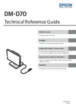
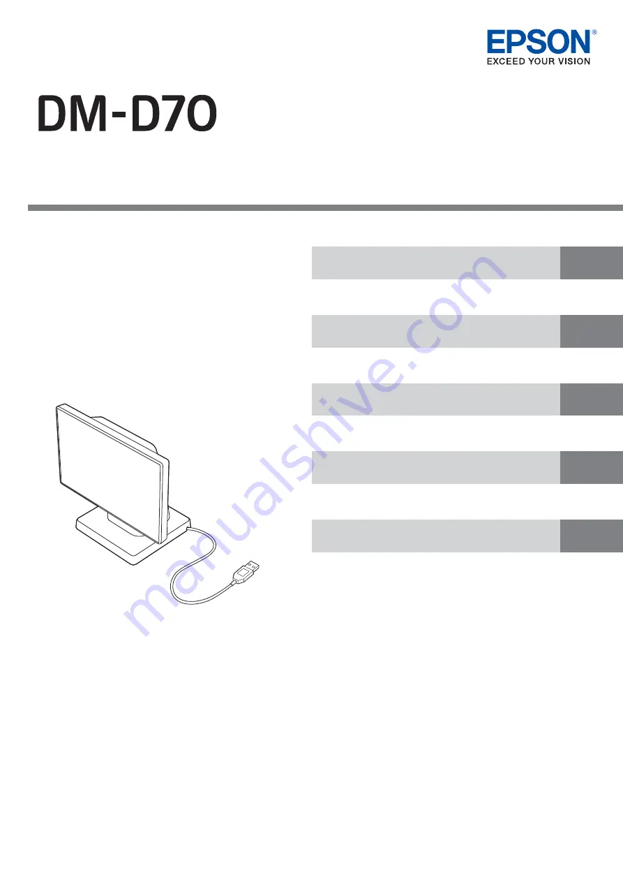
Technical Reference Guide

Describes features of the product.

Describes basic procedure for handling the product.

Provides information for controlling the product and for developing 
application software.

Describes product specifications and character code tables.

Describes how to install the product in portrait orientation and 
how to install with an optional or commercially-available product.

M00134201

Rev. B

Product Overview

Handling

Installing the Product in Various Ways

Application Development Information

Appendix

Summary of Contents for DM-D70

Page 1: ...ct and for developing application software Describes product specifications and character code tables Describes how to install the product in portrait orientation and how to install with an optional or commercially available product M00134201 Rev B Product Overview Handling Installing the Product in Various Ways Application Development Information Appendix ...

Page 2: ...consumable products other than those designated as Original Epson Products or Epson Approved Products by Seiko Epson Corporation Trademarks EPSON EXCEED YOUR VISION and ESC POS are registered trademarks of Seiko Epson Corporation Microsoft and Windows are registered trademarks of Microsoft Corporation in the United States and other countries IOS is a trademark or registered trademark of Cisco in t...

Page 3: ...ccidents such as fire electric shock or burn Do not use aerosol sprayers containing flammable gas inside or around the product Do not cover the product with cloth or place the product in locations subject to high levels of humidity or dust Do not allow foreign objects or flammable objects to fall into the product Do not touch the inside of the product except where mentioned in the manual Do not us...

Page 4: ...his product only after giving consideration to including fail safes and redundancies into your design to maintain safety and total system reliability Because this product was not intended for use in applications requiring extremely high reliability safety such as aerospace equipment main communication equipment nuclear power control equipment or medical equip ment related to direct medical care et...

Page 5: ...s which are necessary for developing designing and installing POS systems Manual Contents The manual is made up of the following sections Chapter 1 Product Overview Chapter 2 Handling Chapter 3 Installing the Product in Various Ways Chapter 4 Application Development Information Chapter 5 Appendix ...

Page 6: ...to TM m30II 12 Connecting to the Computer 13 Routing the USB Cable 13 Changing the Angle of the Display Unit 14 Turning the Power On Off 14 Adjusting the Display Brightness 15 Cleaning the Outer Case 16 Troubleshooting 17 Nothing is Displayed on the Screen 17 The Screen Looks Dark when the Display is Attached in Portrait Orientation 17 Installing the Product in Various Ways 19 Changing the Display...

Page 7: ...38 Display Mode 38 Standard Mode 38 Fixed Column and Row Mode 41 Displaying Character String 42 Displaying QR Code 42 Displaying Graphics Data 43 Storing Graphics Data 43 Available Functions by Display Mode 44 List of Settings 45 Appendix 46 Configurable Number of Columns and Rows 46 When Installed in Landscape Orientation 46 When Installed in Portrait Orientation 48 Supported Printers 50 Product ...

Page 8: ...act body Both landscape and portrait orientations are available The product is USB bus powered Complies with VESA standard 75 x 75mm A commercially available VESA mount such as a wall bracket or arm stand can be attached To meet various requirements EXTENSION POLE UNIT FOR DM D70 and CRANK POLE UNIT FOR TM T88VI DT2 are available as an option Display Easy to see large screen Images can be displaye...

Page 9: ... Customer display Ferrite core Use this when connecting the product to TM m30II Manuals Optional Kits Model number Description DP 70 EXTENSION POLE UNIT FOR DM D70 Extension pole about 24 cm tall USB extension cable about 1 0 m length Stickers for fixing the product 4 pieces DP 71 CRANK POLE UNIT FOR TM T88VI DT2 Crank pole Screws 3 pieces OT UL30 USB extension cable about 1 0 m length ...

Page 10: ...rinter or a computer 4 Rear cover Remove this cover when operating the brightness up down buttons or when changing the display orientation from landscape to portrait 5 Screws 4 pieces Remove the screws when changing the display orientation from landscape to portrait or when connecting the display to a VESA mount The screws can be turned by hand 6 Brightness up down buttons Allows you to adjust the...

Page 11: ... TM T88VI TM T88VI iHUB TM T88VI DT2 TM T70II DT2 Make sure to turn the printer off and then connect this product The product cannot be connected to the USB A Device Charging iPad2 1A connector that is mounted on TM m30II H or other printers If you want to extend the USB cable use the optional USB extension cable OT UL30 The optional kit EXTENSION POLE UNIT FOR DM D70 DP 70 includes a USB extensio...

Page 12: ...Bring the ferrite core close to the body of TM m30II as much as possible 1 Turn off the TM m30II printer and disconnect the AC cable of the AC adapter from the power outlet 2 Put the DC cable of TM m30II into the ferrite core 3 Wrap the cable around the ferrite core once 4 Close the ferrite core until it clicks 5 Connect the AC cable to a power outlet ...

Page 13: ...mputer Routing the USB Cable The USB cable can be routed to one of the three directions Put the USB cable into the groove on the bottom of the stand to secure it If you want to extend the USB cable use the optional USB extension cable OT UL30 The optional kit EXTENSION POLE UNIT FOR DM D70 DP 70 includes a USB extension cable ...

Page 14: ...the left or right Turning the Power On Off Since this product is bus powered there is no power switch The product takes its power from the printer or the computer through the USB cable Do not attempt to move the display to an angle outside the allowable range Doing so may cause the display to malfunction When the product is powered an EPSON logo is displayed Even when the power LED of the printer ...

Page 15: ... by pressing the brightness up down buttons 1 Turn on the display by connecting it to the printer or a computer 2 Remove the rear cover 3 Press the brightness up down buttons to adjust the brightness There are four brightness levels 4 Attach the rear cover It is set to the brightest setting by default ...

Page 16: ...puter and then wipe the customer display with a dry cloth or a cloth dampened with a little water CAUTION Never clean the product with alcohol benzine thinner or other such solvents Doing so may damage or break the parts made of plastic and rubber Rubbing the LCD screen with too much force using a dry cloth may scratch the surface ...

Page 17: ...t or the left and may look differently when viewed from the opposite side This is caused by gray scale inversion phenomenon If that happens adjust the angle of the display However if you cannot adjust the angle for example when you have fixed the display to a VESA mount follow the procedure below to make the screen appear brighter 1 Remove the display and reattach it to the mount upside down 2 Che...

Page 18: ...18 Chapter 2 Handling 4 Start the utility and change Display Settings Display direction to Upside down to flip the screen vertically ...

Page 19: ...Ways Changing the Display Orientation to Portrait Follow the procedure below to change the display orientation to portrait 1 Place the product screen side down on a soft cloth or the like Change the display orientation to portrait if your application software supports portrait display ...

Page 20: ...20 Chapter 3 Installing the Product in Various Ways 2 Remove the rear cover 3 Remove the four screws 4 Release the USB cable from the notch and then remove the stand ...

Page 21: ...alling the Product in Various Ways 5 Change orientation of the stand referring to the mark on the rear of the display 6 Secure the stand with the four screws 7 Route the USB cable as shown below 8 Attach the rear cover ...

Page 22: ...ing the Display to a VESA Mount Follow the procedure below to attach the display to a mount such as a wall bracket or arm stand that complies with VESA standard 75 x 75 mm 1 Place the product screen side down on a soft cloth or the like 2 Remove the rear cover ...

Page 23: ...move the stand and then pull out the USB cable from the stand 5 Attach the display to a VESA mount such as a wall bracket or arm stand Follow the instruction manual for the VESA mount to attach the mount Check the marks on the rear of the display to know which side is top or bottom ...

Page 24: ...splay to the Optional Kit Attaching the EXTENSION POLE UNIT FOR DM D70 DP 70 Follow the procedure below to attach the optional kit EXTENSION POLE UNIT FOR DM D70 DP 70 Contents of the DP 70 package 2 USB extension cable 3 Stickers for fixing the product 1 Extension pole ...

Page 25: ...25 Chapter 3 Installing the Product in Various Ways 1 Place the product screen side down on a soft cloth or the like 2 Raise the stand 3 Push the tabs inward and pull out the stand ...

Page 26: ...ling the Product in Various Ways 4 Pass the USB cable through the extension pole 5 Attach the extension pole to the display Insert the tab on the pole into the groove on the display 6 Pass the USB cable through the stand ...

Page 27: ...rt the tab on the stand into the groove on the pole 8 Secure the USB cable by fitting it into the groove and then route the cable so that it passes through one of the three notches Make sure to fit the cable into the groove to secure the cable properly 9 Connect the USB extension cable if necessary ...

Page 28: ...in Various Ways 10Attach the four stickers to the bottom of the stand To prevent the product from falling over use the stickers to secure the product to a table desk or etc To remove the extension pole from the display pull the pole hard ...

Page 29: ... DT2 DP 71 Follow the procedure below to attach the optional kit CRANK POLE UNIT FOR TM T88VI DT2 DP 71 Contents of the DP 71 package 1 Remove the connector cover of the TM T88VI DT2 Push both lower sides of the cover inward to disengage the hooks and remove the cover 1 Crank pole 2 Three screws ...

Page 30: ...30 Chapter 3 Installing the Product in Various Ways 2 Remove the U shape part from the connector cover 3 Place the product screen side down on a soft cloth or the like 4 Raise the stand ...

Page 31: ...31 Chapter 3 Installing the Product in Various Ways 5 Push the tabs inward and pull out the stand 6 Pass the USB cable through the crank pole ...

Page 32: ...3 Installing the Product in Various Ways 7 Attach the crank pole to the display as shown below 8 Secure the USB cable to the crank pole 9 Lay TM T88VI DT2 on its side 10Pass the USB cable through the TM T88VI DT2 ...

Page 33: ...33 Chapter 3 Installing the Product in Various Ways 11Secure the display and crank pole with the three screws 12Connect the USB cable to the connector on the TM T88VI DT2 13Attach the connector cover ...

Page 34: ...er an HTTP connection ePOS Print Service that is pre installed on the XML compatible printer receives the request and printing or displaying data is performed according to the request For more details about ePOS Print XML see the ePOS Print XML User s Manual ePOS Device XML ePOS Device XML is the Epson original control command system defined using xml for POS printers and peripheral devices This a...

Page 35: ...commands you can directly control all the product functions but comparing to using drivers and the development kit more detailed information about the product specifications and combination of commands are required For details on the ESC POS commands see ESC POS Command Reference for Customer Displays by accessing the URL below U www epson biz com pos reference ...

Page 36: ...oid for iOS for JavaScript EPSON OPOS ADK OCX driver that controls the POS peripheral devices using the OLE technologies Because controlling POS peripherals with original commands is not required on the application side efficient system development is possible EPSON OPOS ADK for NET The OPOS ADK for NET is a POS industry standard printer driver compatible with Microsoft POS for NET It allows you t...

Page 37: ...lity A utility that is available on the App Store or Google Play You can change settings of the product from an iOS or Android device Use this utility to Configure the screen layout settings Store data for slide show Store frame data Run an operation check Store image data Change display settings Android iOS Deployment Tool This allows you to make the settings of the product the printer and the ne...

Page 38: ...lays character string and the image area displays graphics data Standard Mode Contents that can be displayed in the text and image areas in the standard mode are as follows Display Mode Description Standard mode All functions of the product can be used in this mode Fixed column and row mode This mode allows you to fix the number of columns and rows to the same as those of DM D30 DM D110 DM D210 or...

Page 39: ...6 Screen Layout Text area Image area Columns x Rows Width x Height pixels Width x Height pixels Full screen 33 x 10 44 x 13 800 x 480 800 x 480 Vertical split divided into right and left 16 x 9 22 x 13 400 x 480 400 x 480 Horizontal split divided into up and down 33 x 5 44 x 6 800 x 240 800 x 240 In the full screen the text area and the image area are laying on top of each other Display each area ...

Page 40: ...0 x 16 22 x 19 480 x 800 480 x 800 Horizontal split divided into up and down 20 x 8 22 x 9 480 x 400 480 x 400 Horizontal split 2 1 Horizontal split 1 2 Text area 1 Image area 2 20 x 5 22 x 6 480 x 267 480 x 533 Text area 2 Image area 1 20 x 11 22 x 12 480 x 533 480 x 267 In the full screen the text area and the image area are laying on top of each other Display each area with attention to the ove...

Page 41: ... the fixed column and row mode are as follows The following screen layouts are available in the fixed column and row mode Display Area Description Text area Character string Frame image PNG Image area Slide show images JPEG PNG Screen Layout Text area Image area Columns x Rows Width x Height pixels Width x Height pixels Horizontal split divided into up and down Display in center 20 x 2 32 x 2 32 x...

Page 42: ... character size partially Displaying QR Code A QR code can be displayed in the text area in the standard mode Note the following points for displaying a QR code Display a QR code so that it fits inside the text area A displayed QR code is not square This is caused by difference in aspect ratio of the pixels on the LCD Since the recognition rate of a QR code varies depending on widths of the module...

Page 43: ... Match the size of each graphics data horizontal and vertical pixel size with the size of the image area If the size of the graphics data is larger than the image area the graphics is reduced so that it fits inside the image area All graphics data used for the slide show need to be uniform in size If they are different in size an immediately preceding image remains Memory Description NV Graphics N...

Page 44: ... or TM Utility to change the settings You cannot change them from your application software Standard mode Fixed column and row mode Text area Image area Text area Image area Changing the number of columns and rows Fixed Displaying character string Changing characters color Changing background color rows Changing background color full screen Displaying a QR code Displaying an image Displaying slide...

Page 45: ...the product receives no data until the back light turns off Default Normally On Code page Allows you to change the code page for the product Default PC437 USA Standard Europe International character set Allows you to change the international character set for the product Default USA Adjust Brightness Allows you to change the brightness of the back light Default 100 ePOS Device XML mode Select DM D...

Page 46: ...ws When Installed in Landscape Orientation Full screen Column Row 1 2 3 4 5 6 7 8 9 10 11 12 13 14 15 16 17 18 19 20 21 22 1 2 3 4 5 6 7 8 9 10 11 12 13 Column Row 23 24 25 26 27 28 29 30 31 32 33 34 35 36 37 38 39 40 41 42 43 44 1 2 3 4 5 6 7 8 9 10 11 12 13 ...

Page 47: ...vided into up and down Column Row 1 2 3 4 5 6 7 8 9 10 11 12 13 14 15 16 17 18 19 20 21 22 1 2 3 4 5 6 7 8 9 10 11 12 13 Column Row 1 2 3 4 5 6 7 8 9 10 11 12 13 14 15 16 17 18 19 20 21 22 1 2 3 4 5 6 Column Row 23 24 25 26 27 28 29 30 31 32 33 34 35 36 37 38 39 40 41 42 43 44 1 2 3 4 5 6 ...

Page 48: ...screen Horizontal split screen divided into up and down Column Row 1 2 3 4 5 6 7 8 9 10 11 12 13 14 15 16 17 18 19 20 21 22 1 2 3 4 5 6 7 8 9 10 11 12 13 14 15 16 17 18 19 Column Row 1 2 3 4 5 6 7 8 9 10 11 12 13 14 15 16 17 18 19 20 21 22 1 2 3 4 5 6 7 8 9 ...

Page 49: ...n at a ratio of 1 2 Horizontal split 2 1 screen divided into up and down at a ratio of 2 1 Column Row 1 2 3 4 5 6 7 8 9 10 11 12 13 14 15 16 17 18 19 20 21 22 1 2 3 4 5 6 Column Row 1 2 3 4 5 6 7 8 9 10 11 12 13 14 15 16 17 18 19 20 21 22 1 2 3 4 5 6 7 8 9 10 11 12 ...

Page 50: ...irmware is not updated Restrictions C When developing a PC POS application software you cannot use EPSON Advanced Printer Driver for DM D which is pre installed in TM T88VI DT2 or TM T70II DT2 because the software does not support DM D70 Download and use EPSON Advanced Printer Driver 6 for DM D70 When developing application software that uses TM DT software you need to update the TM DT software to...

Page 51: ...0 2000 28 553 characters Traditional Chinese Big5 13 502 characters Korean KS C5601 8 224 characters Character code Unicode 3 UTF 8 Numbers of characters displayed Landscape Standard mode Alphanumeric 44 columns x 13 rows Max Kanji 22 columns x 13 rows Max Landscape Fixed column and row mode Alphanumeric 20 columns x 2 rows 32 columns x 2 rows 32 columns x 3 rows 32 columns x 4 rows 42 columns x 8...

Page 52: ... installed on the product can be displayed For instructions and more detailed information for displaying Unicode characters see ESC POS Command Reference Guide see the explanation of commands that start from US N or software manuals Application Development Information on page 34 ...

Page 53: ...rating environment Storage 10 to 50 C 14 to 122 F 10 to 90 RH non condensing 39 0 C 102 2 F of wet bulb temperature Vibration resistance 1 Operating Frequency 10 to 150 Hz Acceleration rat Approx 4 9 m s2 0 5G Sweep 10 minutes one way Time 1 hour Directions XYZ Before unpacking Frequency 10 to 55 Hz Acceleration rate Approx 19 6 m s2 2G Sweep 10 minutes one way Time 1 hour Directions XYZ Impact re...

Page 54: ...54 Appendix External Dimensions When Installed in Landscape Orientation When Installed in Portrait Orientation 180 109 109 116 165 2 Unit mm 116 109 109 197 2 180 Unit mm ...

Page 55: ...55 Appendix Display Only When Attached to DP 70 180 116 24 8 75 75 Unit mm 116 412 180 109 109 4 7 Unit mm 444 116 109 109 4 7 180 Unit mm ...

Page 56: ...56 Appendix When Attached to DP 71 180 353 4 334 245 8 116 Unit mm 116 353 4 334 180 277 8 Unit mm ...

Page 57: ...57 Appendix Character Code Tables Refer to the following URL regarding the Character Code Tables for Customer Displays U www epson biz com pos reference ...

Page 58: ...ttps www sourceware org newlib COPYING NEWLIB CMSIS RTOS 4 80 Redistributed binary BSD 3 Clause License https www renesas com jp ja software D6003896 html an r01an3638ej0212 rza1 fwp Software CMSIS_RTOS_RTX RT OS RTX License txt Included in the downloaded files lwIP 1 4 1 Redistributed binary BSD 3 Clause License https lwip fandom com wiki LwIP_Wiki https lwip fandom com wiki License Renesas Graph...

Reviews: