6
EPSON
E0C6006 TECHNICAL MANUAL
CHAPTER 2: POWER SUPPLY AND INITIAL RESET
2.2 Initial Reset
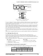
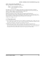
The E0C6006 must be initially reset to initialize its circuits. Initial reset is triggered by an external reset
(RESET) signal, oscillation detector signal, or watchdog timer signal. The RESET input is needed for
initialization at power-on.
OSC1
oscillation
circuit
Watchdog
timer
Oscillation
detector
WDRST
Initial reset
V
DD
f
OSC1
OSC1
OSC2
E0C6006
RESET
Fig. 2.2.1 Initial reset circuit configuration
2.2.1 Reset at power-on
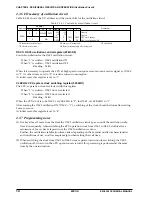
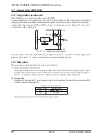
At power-on, the initial reset signal has two functions. One function is to initialize a circuit and the other
to sustain the initializing function until the OSC3 oscillation is stabilized. Thus, the RESET input must be
held at low level for at least 0.5 second after power-on.
After the RESET input reaches the high level and the OSC1 oscillation circuit starts operating, several
milliseconds later, the system is released from internal reset and starts to operate.
V
DD
OSC3
RESET
Detect oscillation
Watchdog timer
Internal initial reset
(Vss : GND)
Fig. 2.2.1.1 Initial reset sequence at power-on
2.2.2 RESET pin
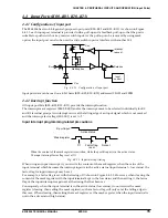
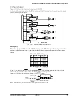
The RESET signal directly initializes the E0C6006. The system is reset when RESET = L, and released from
the reset state when RESET = H. As the RESET pin is pulled up and receives a schmitt trigger input, it can
be used as a power-on reset circuit if the RESET pin is connected with the V
SS
pin via a capacitor as
shown in Figure 2.2.2.1. A reset switch must be provided to obtain an assured reset effect at power-on
without being influenced by possible power. This is especially important for a reset operation without the
use of the OSC3 oscillation circuit, in which case the system clock (OSC1) must be ON before the system
is released from the reset state.
To reset circuit
C
RESET
SR
E0C6006
V
DD
V
SS
V
SS
Fig. 2.2.2.1 Power-on reset circuit


