


E0C6006 TECHNICAL MANUAL
EPSON
31
CHAPTER 4: PERIPHERAL CIRCUITS AND OPERATION (Remote Controller)
This remote controller supports the following two modes for controlling the modulation signal (carrier
ON/OFF).
• Soft-timer mode (Software timer control mode)
• Hard-timer mode (Hardware timer control mode)
In the soft-timer mode, the carrier ON/OFF timing and the time are controlled by the software. The
optional ON/OFF time can be set within the range that is controlled by the software.
In the hard-timer mode, the carrier ON/OFF timing and the output time are controlled by the REMOUT
time generator based on the reference cycle (
τ
) that is generated by the
τ
(reference cycle) generation
circuit dividing the carrier. For the reference cycle (
τ
), the carrier dividing ratio can be selected by the
software from 4 types. The REMOUT (REM output) time can be selected by the software from 4 types, 0
to 3 times as long as the reference cycle (
τ
). The ON/OFF time is limited to some extent in comparison
with the soft-timer mode, but the software's share is decreased because the interrupt can be used.
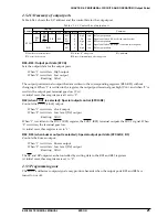
Features of the soft-timer mode and hard-timer mode are shown in Table 4.9.1.1.
Table 4.9.1.1 Features of soft-timer mode and hard-timer mode
Item
Processing of other routines during REM output
Reference cycle (
τ
) sway
during REM transmission
Setting of REM output width
Relation between REM reference cycle
and modulation frequency cycle
Carrier waveform
Possible
Source oscillation sway only
Fixed to several widths
Fixed to several cycles
Stabilized at setting
Hard-timer mode
Difficult
Source oscillation sway and errors
caused by instruction cycles
Variable to any width
Variable
Duty slightly disturbed before and after ON time
Soft-timer mode
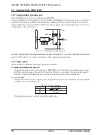
4.9.2 Carrier
The carrier is generated by the carrier generation circuit using the OSC3 clock as the source clock.
Note: If an option is selected without use of OSC3, the OSC1 clock (instead of the OSC3 clock) is
introduced into the REM circuit. For an option selected without using OSC3, the term "OSC3"
should read "OSC1" in the description that follows.
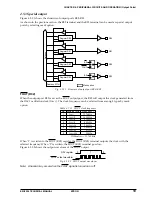
The carrier cycle and duty ratio selections and the carrier generation circuit ON/OFF control can be done
by the software.
The control for the carrier is same procedure for both the soft-timer mode and the hard-timer mode.
Perform the carrier settings before starting the transmission in each mode.
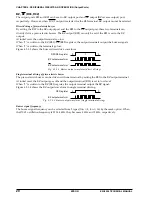
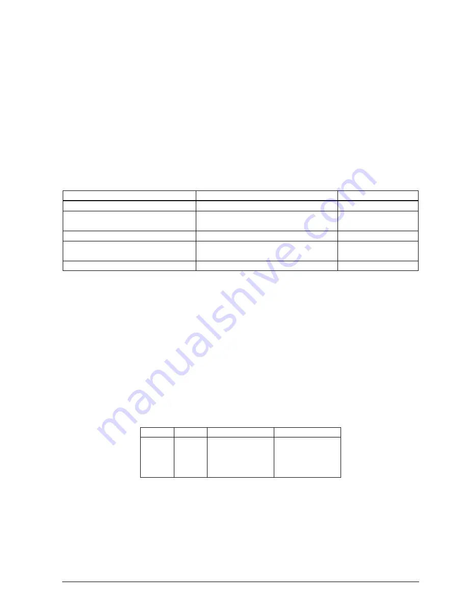
The carrier cycle (selection as the dividing ratio of the OSC3 clock) and the duty ratio can be set using the
RCDIV register (F7H•D3) and RCDUTY register (F7H•D2) as shown in Table 4.9.2.1.
Table 4.9.2.1 Carrier dividing ratio and duty ratio
RCDIV
0
0
1
1
RCDUTY
0
1
0
1
Carrier dividing ratio
f
OSC3
/ 8
f
OSC3
/ 8
f
OSC3
/ 12
f
OSC3
/ 12
f
OSC3
: OSC3 oscillation frequency
Carrier duty ratio
1/4
3/8
1/3
1/4
Carrier settings can be done even when the OSC3 oscillation circuit is in OFF status. Furthermore, when
these are set once, the set contents are maintained until an initial reset is performed.
Note: The setting of the RCDIV register and the RCDUTY register should be done when the REM circuit
is OFF (REMC = "0") before starting remote transmission. If changing the contents when the REM
circuit is ON, it may cause a malfunction.


