48
EPSON
E0C6006 TECHNICAL MANUAL
CHAPTER 6: ELECTRICAL CHARACTERISTICS
CHAPTER
6 E
LECTRICAL
C
HARACTERISTICS
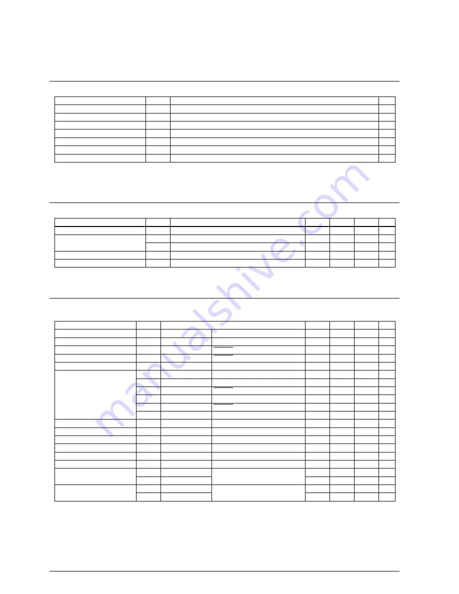
6.1 Absolute Maximum Rating
Item
Supply voltage
Input voltage (1)
Input voltage (2)
Operating temperature
Storage temperature
Soldering temperature / time
Permissible dissipation
∗
1
∗
1
(V
DD
=0V)
Symbol
V
SS
V
I
V
IOSC
Topr
Tstg
Tsol
P
D
Rated value
-5.2 to 0.5
V
SS
- 0.3 to 0.3
V
S1
- 0.3 to 0.3
-20 to 70
-65 to 150
260
°
C, 10sec (lead section)
250
Unit
V
V
V
°
C
°
C
–
mW
In case of plastic package (QFP6-60pin, QFP13-64pin).
6.2 Recommended Operating Conditions
Item
Supply voltage
Oscillation frequency
LCD drive voltage
CR oscillation external resistor
(Ta=-20 to 70
°
C)
Symbol
V
SS
f
OSC1
f
OSC3
V
L1
R
CR
Unit
V
kHz
kHz
V
k
Ω
Max.
-2.2
–
600
–
500
Typ.
-3.0
32.768
455
-1.03
140
Min.
-3.5
–
50
-1.6
100
Condition
V
DD
=0V
Duty: 50
±
5%
6.3 DC Characteristics
Item
High level input voltage (1)
Low level input voltage (1)
High level input voltage (2)
Low level input voltage (2)
High level input current
Low level input current
High level output current (1)
Low level output current (1)
High level output current (2)
Low level output current (2)
High level output current (3)
Low level output current (3)
Common output current
Segment output current
(during LCD output)
∗
1
Unless otherwise specified:
V
DD
=0V, V
SS
=-2.2 to -3.5V, V
L3
=-3.0V, Ta=-20 to 70
°
C
Symbol
V
IH1
V
IL1
V
IH2
V
IL2
I
IH
I
IL1
I
IL2
I
IL3
I
IL4
I
IL5
I
IL6
I
OH1
I
OL1
I
OH2
I
OL2
I
OH3
I
OL3
I
OH4
I
OL4
I
OH5
I
OL5
Unit
V
V
V
V
µ
A
µ
A
µ
A
µ
A
µ
A
µ
A
µ
A
µ
A
mA
µ
A
mA
mA
mA
µ
A
µ
A
µ
A
µ
A
Max.
0
0.8·V
SS
0
0.9·V
SS
1
-0.35
-0.35
-2
-250
-250
-1.8
-3.0
-3.0
Typ.
Min.
0.2·V
SS
V
SS
0.1·V
SS
V
SS
-1
-5
-5
-50
-50
-13
1.0
1.0
1.0
3.0
3.0
Only at read cycle using internal program.
Condition
K00–03, K10–13, P00–03
K00–03, K10–13, P00–03
RESET
RESET
V
IH
=V
DD
V
IL1
=V
SS
K00–03, K10–13, No pull-up
V
IL2
=V
SS
K00–03, K10–13, Pull-up
V
IL3
=V
SS
RESET
V
IL4
=0.2·V
SS
K00–03, K10–13, Pull-up
V
IL5
=0.2·V
SS
RESET
V
IL6
=V
SS
P00–03 *
1
V
OH1
=0.1·V
SS
R00–03
V
OL1
=0.9·V
SS
R00–03
V
OH2
=0.1·V
SS
P00–03
V
OL2
=0.9·V
SS
P00–03
V
OH3
=0.1·V
SS
R33(REM)
V
OL3
=0.9·V
SS
R33(REM)
V
OH4
=-0.05V
COM0–3
V
OL4
=V
L3
+0.05V
V
OH5
=-0.05V
SEG0–19
V
OL5
=V
L3
+0.05V


