


3 FUNCTION OPTION GENERATOR FOG6011
E0C6011 DEVELOPMENT TOOL MANUAL
EPSON
15
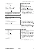
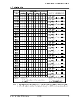
The LCD drive bias is decided according to the LCD
voltage selection of Option 1.
When 4.5 V LCD is selected, the LCD drive bias is
set to 1/3 (drives LCD with 4 levels, V
DD
, V
L1
, V
L2
and V
L3
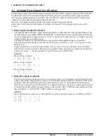
). When 3 V LCD is selected, the LCD drive
bias is set to 1/2 (drives LCD with 3 levels, V
DD
, V
L1
= V
L2
and V
L3
).
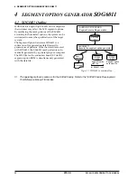
Figure 3.3.9 shows the external element configuration
for the LCD voltage selected by Option 1.
The LCDON register (0FFH•D0) is used for turning
the LCD display ON and OFF.
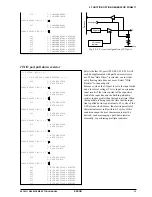
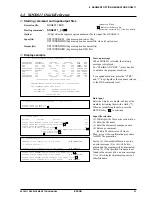
12 Segment memory address
Select the segment memory area.
When "40H–6FH" is selected for the segment
memory area, it is possible to read and write from/to
this area because a RAM is assigned to this area.
When "C0H–EFH" is selected, this segment memory
area becomes a write-only area.
*** OPTION NO.12 ***
--- << SEGMENT MEMORY ADDRESS SELECT >> ---
1. 40H-6FH
2. C0H-EFH
PLEASE SELECT NO.(1) ? 2
2. C0H-EFH SELECTED
V
DD
V
L1
V
L2
V
L3
CA
CB
V
SS
1.5 V
C2
C3
C1
0.1
µ
F
0.1
µ
F
0.1
µ
F
V
DD
V
L1
=V
SS
V
L2
=2V
L1
V
L3
=3V
L1
V
SS
4.5 V LCD Panel
1/4, 1/3 or 1/2 duty, 1/3 bias
V
L1
and V
SS
are shorted internally.
Note:
LCD
voltage
circuit
V
DD
V
L1
V
L2
V
L3
CA
CB
V
SS
1.5 V
C2
C1
0.1
µ
F
0.1
µ
F
V
DD
V
L1
=V
SS
V
L2
=V
SS
V
L3
=2V
L1
V
SS
3 V LCD Panel
1/4, 1/3 or 1/2 duty, 1/2 bias
V
L1
and V
SS
are shorted internally.
Note:
LCD
voltage
circuit
Fig. 3.3.9 External elements for LCD power supply circuit


