Maintenance 4. Replacing the Cable Unit
Installation
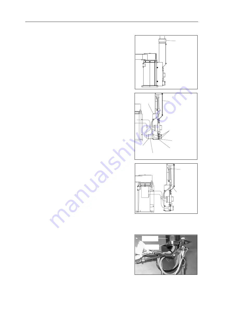
(1) Pass cables through the base connector box
and a nut.
Secure the duct joint with the nut.
Duct joint
(2) Connect pneumatic tubes, ground wire, and
connectors.
For details, refer to
Maintenance: 4.3
Wiring Schematics/4.4 Block Diagrams
.
(3) Secure a receptacle to the base connector
box.
Receptacle
4-M3
×
8
Ground terminal
Pneumatic tube
fittings
8-M4
×
8
Connector cover
Connector
box
(4) Fasten the cables with a wire tie inside the
main cable elbow fitting.
Attach a ferrite core to the bundle and
install the connector cover.
Wire tie
Ferrite core
(5) Install the base connector box.
For details on the installation method, refer to
Maintenance: 3.4 Base Connector Box
.
(6) Pass the cable unit through the arm top
cover and duct plate.
Install the duct joint to the duct plate.
Duct joint
Lock nut
90
E2C Rev.6
Summary of Contents for E2C Series
Page 1: ...SCARA ROBOT E2C series MANIPULATOR MANUAL Rev 6 EM069R1409F ...
Page 2: ...MANIPULATOR MANUAL E2C series Rev 6 ...
Page 8: ...vi E2C Rev 6 ...
Page 14: ......
Page 82: ......
Page 92: ...Maintenance 2 General Maintenance 80 E2C Rev 6 ...
Page 118: ...Maintenance 4 Replacing the Cable Unit 106 E2C Rev 6 ...
Page 194: ...Maintenance 11 Replacing the Signal Relay Board 182 E2C Rev 6 ...


