Maintenance 11. Replacing the Signal Relay Board
E2C Rev.6
181
Installation
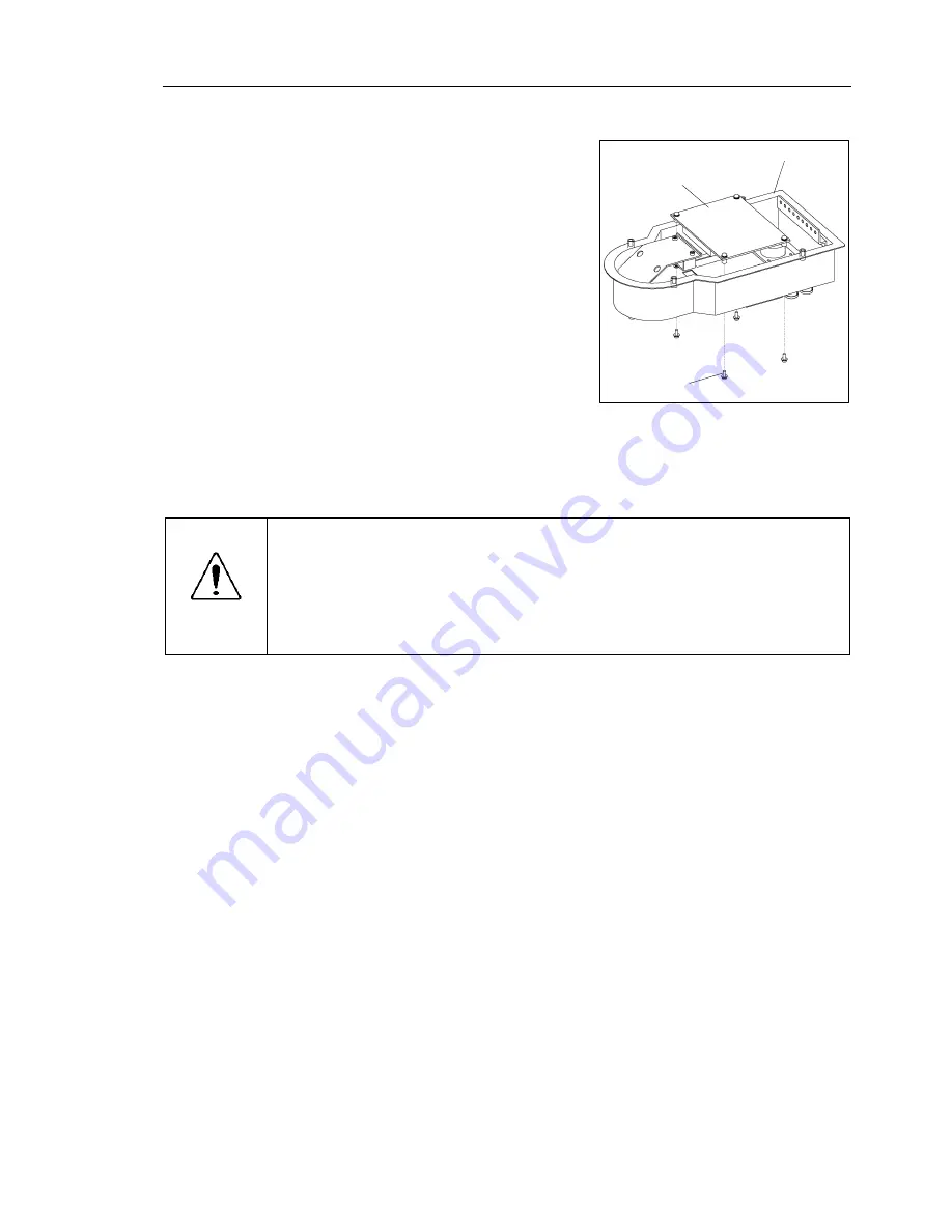
(1) Install a new signal relay board to the base
connector box.
Secure the board from the outside of the
box.
4-M3
×
6
Signal relay
board
Base connector box
(2) Connect the connectors (X10, X20, X30, X40, X50, and X4) to the signal relay
board.
CAUTION
■
Be sure to connect the cables properly. Do not allow unnecessary strain on the
cables. (Do not put heavy objects on the cables. Do not bend or pull the cables
forcibly.) The unnecessary strain on the cables may result in damage to the
cables, disconnection, and/or contact failure. Damaged cables, disconnection,
or contact failure is extremely hazardous and may result in electric shock and/or
improper function of the robot system.
(3) Install the base connector box.
For details on the installation method, refer to
Maintenance: 3.4 Base Connector Box
.
(4) Connect the connectors and tubes to the base connector box (outside).
(5) Turn ON the Controller.
(6) Check if the Manipulator moves to the points (pose) correctly.
To do so, select 2 points (pose) or more from the registered points (pose) and move
the Manipulator to the points (pose).
(7) If the Manipulator does not move to the points (pose) correctly, perform the
calibration of all joints and axes.
For details on the calibration method, refer to
Maintenance: 14. Calibration
.
Summary of Contents for E2C Series
Page 1: ...SCARA ROBOT E2C series MANIPULATOR MANUAL Rev 6 EM069R1409F ...
Page 2: ...MANIPULATOR MANUAL E2C series Rev 6 ...
Page 8: ...vi E2C Rev 6 ...
Page 14: ......
Page 82: ......
Page 92: ...Maintenance 2 General Maintenance 80 E2C Rev 6 ...
Page 118: ...Maintenance 4 Replacing the Cable Unit 106 E2C Rev 6 ...
Page 194: ...Maintenance 11 Replacing the Signal Relay Board 182 E2C Rev 6 ...


