Maintenance 14. Calibration
E2C Rev.6
191
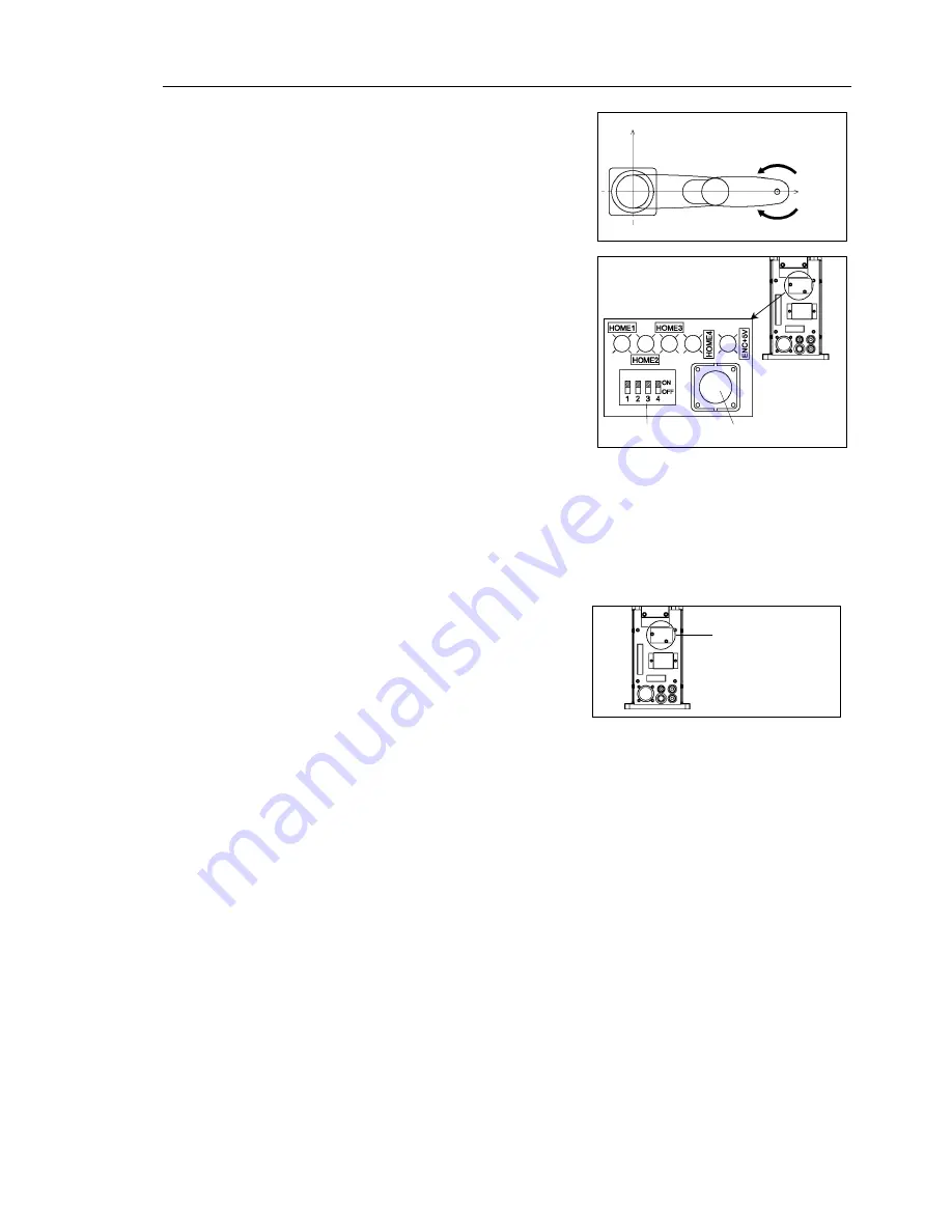
0 pulse position of Joint #4:
position where the flat surface on the
shaft faces toward the tip of Arm #2
0 pulse
(4) Remove the acrylic plate on the sensor
monitor on the base connector box.
Sensor monitor
Reset switch
DIP switch
(5) Set the DIP switch corresponding to the joint that needs origin alignment to its ON
position. For Joint #4, place both “3” and “4” in their ON positions.
(6) Press and hold the reset switch for 1 or more seconds.
Error will still be displayed. (SPEL CT: F-5136, EPSON RC+: 5136)
(7) Return the DIP switch(s) to the OFF position.
(8) Re-install the acrylic plate on the sensor
monitor.
Sensor monitor
(9) SPEL CT
: Reboot SPEL CT.
EPSON RC+ 4.* : Right-click the <SPEL Runtime Drivers system tray> icon, and
select [Restart SPEL Drivers].
EPSON RC+ 5.* : Select menu-[Tools]-[Controller], and click the [Restart
Controller] button.
(10) Open the [Robot Control] window and click on the Motor <ON> button.
Error [Absolute Encoder has been initialized] is displayed.
(SPEL CT: F-5136, EPSON RC+: 5136)
Click the <RESET> button. (The error is cleared.)
(11) Enter the current position that is visually determined as the 0 pulse position to
perform a rough calibration.
>CALPLS 0,0,0,0
Summary of Contents for E2C Series
Page 1: ...SCARA ROBOT E2C series MANIPULATOR MANUAL Rev 6 EM069R1409F ...
Page 2: ...MANIPULATOR MANUAL E2C series Rev 6 ...
Page 8: ...vi E2C Rev 6 ...
Page 14: ......
Page 82: ......
Page 92: ...Maintenance 2 General Maintenance 80 E2C Rev 6 ...
Page 118: ...Maintenance 4 Replacing the Cable Unit 106 E2C Rev 6 ...
Page 194: ...Maintenance 11 Replacing the Signal Relay Board 182 E2C Rev 6 ...


