Introduction
8
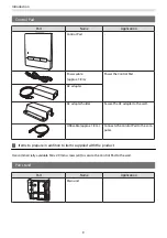
Part
Name
Application
Infrared deflectors
(approx. 28.5 cm) x12
Use these when there is a tray or frame
at the bottom of the projection surface.
This prevents malfunctions due to laser
reflections.
Spacers for screw holes x3
Attach them to the screw hole when
securing the Touch Unit with screws.
Label x4
Attach the label in the position of the
Touch Unit. These provide markers
when repositioning due to movement
that occurs during use.
Items to prepare in addition to items supplied with the product
When securing the Touch Unit with screws, prepare two commercially available M4 screws.
Touch Unit Bracket
Use this when attaching the Touch Unit to outside of the projection surface.
Part
Name
Application
Touch Unit Bracket
-
Template sheet (for Touch
Unit Bracket)
Attach this to the wall before attaching
the Touch Unit Bracket, and use it to
drill necessary holes.
M4 x 25mm hexagon socket
head cap bolts (x2)
Secure the Touch Unit to the Touch
Unit Bracket.
Hexagon wrench (for M4)
-
Items to prepare in addition to items supplied with the product
Use commercially available anchor bolts or screws to secure the Touch Unit Bracket to the wall.
M4 anchor bolts (x4)
3.8 mm diameter wood screws with a length of 45 mm or more (x4)
Summary of Contents for ELPHD02
Page 1: ...Installation Guide ...
Page 18: ...Introduction 17 Max 5m Max 5m ...
Page 29: ...Installing the Wall mount 28 Horizontal slide 45 45 Forward backward slide 0 383 ...
Page 77: ...Installing the Control Pad 76 For Canadian Users ...
Page 79: ...Installing the Control Pad 78 ...
Page 96: ...Installing the Touch Unit 95 Wavelength 932 to 952 nm ...
Page 99: ...Installing the Touch Unit 98 Adjustment range 79 5 140 5 15 76 ...
Page 138: ...Setting the Projector 137 c Select EDID from the Signal I O menu d Select 3240x1080 60Hz ...

