background image

ISSUED: 02-13-08  SHEET #: 128-9029-2 07-10-08

4 of 6

Visit  the  Peerless  Web  Site  at  www.peerlessmounts.com

For Technical Support Contact Peerless Mounts at 1-800-729-0307 or 708-865-8870.

IMPORTANT PRE-ASSEMBLY
INFORMATION:

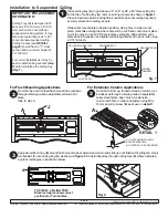
Ceiling Tray (

A

) is designed to fit

above a 24" (610 mm) x 24" (610
mm) section of a conventional
suspended ceiling system. It may
also be mounted above 24" x 48"
conventional suspended ceiling.
Ceiling runners (see 

DETAIL 2,

page 5

) should have a “T” cross

section and a minimum height of
1.5" (38 mm).

For certain installations it may be
best to install ceiling anchors 

(step

5)

 before installing the ceiling tray

(step 1)

.

Place ceiling tray (

A

) in grid above 24" x 24" or 24" x 48" false ceiling tile

so that lip of ceiling tray (

A

) rests on ceiling runners as shown in 

figure 1

.

Place in desired position and tighten knurled knobs until ceiling tray (

A

) is

securely attached to ceiling runners.

Slide collar mount plate to desired position. Using hole in collar mount
plate, mark false ceiling tile where hole will be cut. Slide collar mount plate
out of the way. Cut out 2.25" hole in false ceiling tile. Slide collar mount
plate back into position and tighten all carriage bolts and nylock nuts using
a 7/16" wrench.

A

CEILING
RUNNER

COLLAR MOUNT PLATE

KNURLED KNOB

CARRIAGE BOLT

NYLOCK NUT

From the top down, thread flush mount tube (

J

) down

through retaining collar in adjustable collar mount
plate.

Skip to step 3.

J

For Flush Mounting Applications

From the bottom up, thread extension column (not
included) up through retaining collar in adjustable
collar mount plate. Align notch in extension
column with hole in collar and fasten using M5 x
10 mm security screw (

K

) as shown in 

detail 1

.

For Extension Column Applications

TOP VIEW - CEILING TRAY
Black rectangles show correct
positions for Turnbuckles.

Snap escutcheon ring (

E

) around flush mount tube or extension column and slide up until flush with ceiling tile.  Hook

turnbuckles (

F

) into ceiling tray (

A

) as shown in 

figure 2

. Hook turnbuckles through ceiling tray (

A

) where indicated

by black rectangles in illustration below.

F

A

1 1/2" EXTENSION COLUMN
(SOLD SEPARATELY)
(UL LISTED EXT OR ADJ SERIES)

K

A

A

1

2

2

3

Installation to Suspended Ceiling

fig. 1

fig. 2

DETAIL 1

Summary of Contents for ELPMBP01

Page 1: ... 8870 Fax 708 865 2941 www peerlessmounts com Maximum UL Load Capacity 50 lb 22 6 kg This product is UL Listed It must be installed by a qualified professional installer R Installation and Assembly Adjustable Suspended Ceiling Channel Kit Manufactured by Peerless Industries Inc ...

Page 2: ...y be installed by someone of good mechanical aptitude has experience with basic building construction and fully understands these instructions Make sure that the supporting surface will safely support the combined load of the equipment and all attached hard ware and components Never exceed the Maximum UL Load Capacity Always use an assistant or mechanical lifting equipment to safely lift and posit...

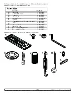
Page 3: ...d all hardware provided NOTE Some parts may appear slightly different than illustrated I H F J K Description Qty Part A ceiling tray 1 055 0492 B 1 4 20 x 3 8 screws 4 520 2015 C 1 4 20 nuts 4 530 9302 D allen wrench 1 560 9706 E escutcheon ring 1 1418 001A F turnbuckle 4 560 9620 G 12 gauge x 20 6 1m tie wire not shown 1 600 2008 H eye bolt 5 580 0006 I concrete anchor 5 580 0005 J flush mount tu...

Page 4: ... hole will be cut Slide collar mount plate out of the way Cut out 2 25 hole in false ceiling tile Slide collar mount plate back into position and tighten all carriage bolts and nylock nuts using a 7 16 wrench A CEILING RUNNER COLLAR MOUNTPLATE KNURLEDKNOB CARRIAGE BOLT NYLOCK NUT From the top down thread flush mount tube J down through retaining collar in adjustable collar mount plate Skip to step...

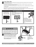
Page 5: ...black will be needed Suspended Ceiling Kit installation is now complete After all components Projector Mount Extension Column etc and equipment have been attached tension the tie wires by adjusting turnbuckles F NOTE Load must be carried by tie wires not suspended ceiling runners A G G G CEILING RUNNER KNOCK OUTS ARE PROVIDED FOR ELECTRICAL OUTLET BOXESANDANTENNA LEADS 2 15 1 5 4 5 VARIOUSANCHORIN...

Page 6: ...DXWKRUL HG IRU VXFK VHUYLFH RU UHSDLUV E 3HHUOHVV QGXVWULHV QF E WKH IDLOXUH WR XWLOL H SURSHU SDFNLQJ ZKHQ UHWXUQLQJ WKH SURGXFW F LQFRUUHFW LQVWDOODWLRQ RU WKH IDLOXUH WR IROORZ 3HHUOHVVҋ LQVWUXFWLRQV RU ZDUQLQJV ZKHQ LQVWDOOLQJ XVLQJ RU VWRULQJ WKH SURGXFW RU G PLVXVH RU DFFLGHQW LQ WUDQVLW RU RWKHUZLVH LQFOXGLQJ LQ FDVHV RI WKLUG SDUW DFWLRQV DQG IRUFH PDMHXUH Q QR HYHQW VKDOO 3HHUOHVV EH OLDE...

Reviews: