background image

EPSON TERMINAL PRINTER

EPL-5500

SERVICE   MANUAL

EPSON

4005431

Summary of Contents for EPL-5500

Page 1: ...EPSON TERMINAL PRINTER EPL 5500 SERVICE MANUAL EPSON 4005431 ...

Page 2: ... ii ...

Page 3: ...of this manual However should any errors be detected SEIKO EPSON would greatly appreciate being informed of them The above notwithstanding SEIKO EPSON can assume no responsibility for any errors in this manual or the consequence thereof Epson is a registered trademark of Seiko Epson Corporation General Notice Other product names used herein are for identication purposes only and may be trademarks ...

Page 4: ... NOT CONNECT THE UNIT TO A POWER SOURCE UNTIL INSTRUCTED TO DO SO WHEN THE POWER SUPPLY CABLE MUST BE CONNECTED USE EXTREME CAUTION IN WORKING ON POWER SUPPLY AND OTHER ELECTRONIC COMPONENTS WARNING 1 REPAIRS ON EPSON PRODUCT SHOULD BE PERFORMED ONLY BY AN EPSON CERTI FIED REPAIR TECHNICIAN 2 MAKE CERTAIN THAT THE SOURCE VOLTAGE IS THE SAME AS THE RATED VOLTAGE LISTED ON THE SERIAL NUMBER RATING P...

Page 5: ...atory for products marketed in the United States The label shown below indicates compliance with the CDRH regulations and must be attached to laser products marketed in the United States WARNING Use of controls adjustments or performance of procedures other than those specified in this manual may result in hazardous radiation exposure Internal Laser Radiation Maximum Radiation Power 5 0 10 4 W Wav...

Page 6: ... suojalukitus ohitettaessa olet alttiina näkymättömälle laser säteilylle Älä katso säteeseen VARNING Osynlig laserstrålning när denna del är öppnad och spärren är urkopplad Betrakta ej strålen For Norway Users ADVARSEL Dersom apparatet brukes på annen måte enn spesifisert i denne bruksanvis ning kan brukeren utsettes for unsynlig laserstråling som overskrider grensen for laser klasse 1 Dette er en...

Page 7: ...For Europe Label inside printer The following laser safety label will be attached inside the printer as shown below For Denmark Finland Sweden and Norway v ...

Page 8: ...s of the printer CHAPTER 2 OPERATING PRINCIPLES Describes the theory of printer operation CHAPTER 3 DISASSEMBLY AND ASSEMBLY Includes a step by step guide for product disassembly and assembly CHAPTER 4 ADJUSTMENTS Includes a step by step guide for adjustment CHAPTER 5 TROUBLESHOOTING Provides Epson approved techniques for adjustment CHAPTER 6 MAINTENANCE Describes preventive maintenance techniques...

Page 9: ...ON SHEET Revision Issue Date Revision Page Rev A October 06 1995 1st issue Rev B March 15 1996 Revise the whole pages of the following chapters Chapter 1 Chapter 2 Chapter 3 Chapter 4 Chapter 5 Chapter 6 vii ...

Page 10: ...Interface 1 17 1 4 OPERATING INSTRUCTIONS 1 18 1 4 1 Control Panel 1 18 1 4 2 Printer Settings Functions 1 20 1 4 3 Service Mode 1 23 1 4 3 1 Heaxadecimal Dump Mode 1 23 1 4 3 2 EEPROM Initialize Mode 1 23 1 4 3 3 Factory Reset Mode 1 23 1 4 3 4 Default Setting Mode 1 24 1 4 4 Display of Messages 1 27 1 4 4 1 Status Messages 1 27 1 4 4 2 Error Messages 1 27 1 4 4 3 Service Call Error Message 1 27 ...

Page 11: ...gure 1 18 C169 MAIN B Board 1 33 Figure 1 19 PWB E Board 1 34 Figure 1 20 PWB F Board 1 34 Figure 1 21 Optical Unit 1 35 Figure 1 22 Fusing Unit 1 35 Figure 1 23 Photoconductor Unit 1 36 Figure 1 24 Developing Cartridge 1 36 List of Tables Table 1 1 Options for the EPL 5500 1 2 Table 1 2 Paper Feed Methods 1 3 Table 1 3 Paper Types 1 3 Table 1 4 Usability of Special Papers 1 4 Table 1 5 Electrical...

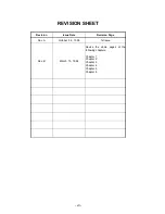
Page 12: ...Rev A 1 iii ...

Page 13: ... and characters on 600 dpi and 300 dpi printing Memory Improvement Technology supported Optional EPSONScript Level 2 PostScript compatible module Optional WPS Windows Printing System ROM SIMM module Optional I239X ESC P 2 and FX emulation ROM SIMM module EPSON Micro Gray Technology EMGTech which is available when using PCL and EPSONScript Level 2 mode refines gray scale printing to be comparable t...

Page 14: ...erial I F module see Note 3 C83614 Interface cable RS 232C extension cable for C82334 C82335 Type B EX box Type B I F card box see Note 4 C82307 C82308 32 KB serial interface card see Note 5 C82310 C82311 32 KB parallel interface card see Note 5 C82312 LocalTalk card see Note 5 C82313 GPIB card see Note 5 C82314 COAX interface card see Note 5 C82315 TWINAX interface card see Note 5 C82324 Ethernet...

Page 15: ...e Usage Thickness Ream Weight Standard built in paper tray 150 A5 B5 A4 LT GLT EXE LGL GLG F4 HL 16 to 24 lb 60 to 90 g m2 5 to 10 Monarch DL C5 C6 International B5 Commercial 10 Envelopes made of 20 to 24 lb 75 to 90 g m2 paper Manual feed slot 1 Any size feedable Note 2 16 to 42 lb 60 to 157 g m2 Lower paper cassette optional 250 A4 B5 16 to 24 lb 60 to 90 g m2 Notes 1 The weight in pounds lb is...

Page 16: ...per Bond paper Recycled paper 16 to 24 lb 60 to 90 g m2 Special papers Card stock 90 to 157 g m2 Envelopes Labels Letterhead Transparency OHP sheets Colored paper Printable Area 4 0 mm 4 0 mm 4 0 mm 4 0 mm Figure 1 2 Printable Area General Description EPL 5500 Service Manual 1 4 Rev B ...

Page 17: ...avoided N Not supported Paper feed alignment and direction Center alignment for all sizes Paper ejection Face down Output tray capacity 100 sheets face down Printable area standard paper See Figure 1 2 Note The actual printable area depends on the printer mode Noise Less than 35 dB A standby Less than 47 dB A operating Ozone density Less than 0 01 ppm Toxicity No toxicity exists in organic photoco...

Page 18: ...tiple paper feeds 1 out of 500 sheets or less Paper curl height 30 mm 1 2 inches or less Leading edge bending 1 cm or more 1 out of 1 000 sheets MTTR Mean Time To Repair 30 minutes or less Durability 5 years or 180 000 sheets 1 2 4 Environmental Conditions for Operation Including Imaging Cartridge Temperature 10 to 35 C 50 to 95 F Humidity 15 to 85 RH Altitude 2 500 m 8 200 feet or lower Levelness...

Page 19: ...SS environmental law must contain no CdS 1 2 7 Specifications for Consumables Life Developer and toner cartridge 3 000 pages Photoconductor unit 20 000 pages Note In continuous printing mode with A4 letter paper at a 5 image ratio black white ratio The life varies depending on the printing mode continuous or intermittent and or the image ratio Environmental Conditions for Storage and Transportatio...

Page 20: ...er and then initializes Ejects paper switches to PCL and then initializes PJL EJL and ES Supported Supported Advance full page PG AF Supported Not supported Note The EPL 5500 GL 2 mode features all the commands of the LJ4 GL 2 mode plus a few additional commands The GL 2 mode emulates some of the HP GL plotter HP 7475A etc commands If the application software uses unsupported commands for the GL 2...

Page 21: ...721Bold SWM S Swiss 721Oblique SWM S Swiss 721Bold Oblique SWM S Dutch 801Roman SWM S Dutch 801Bold SWM S Dutch 801Italic SWM S Dutch 801Bold Italic SWM S Symbol SetSWA S More WingBatsSWM S CourierSWC S CourierBold SWC S CourierItalic SWC S CourierBold Italic SWC S S Supported NS Not Supported General Description EPL 5500 Service Manual 1 8 Rev B ...

Page 22: ...Interface Compatibility Mode System STROBE synchronization 8 bit parallel data transfer Handshaking BUSY and ACKNLG signals Connector type P90 25027 1 Amphenol receptacle Applicable plug 57 30360 Amphenol or equivalent Transfer speed Approximately 400 000 bytes second max Signal timing See Figure 1 3 Signal description See Table 1 8 DATA 1 8 STROBE BUSY ACKNLG VALID VALID 0 5 µs minimum 0 5 µs min...

Page 23: ...cified through SelecType 11 BUSY OUT The BUSY signal informs the host computer of the printer state When the signal is HIGH the printer cannot accept data 12 PE OUT The PE signal indicates paper empty for the standard tray selected through SelecType or command or for the optional paper cassette Paper empty is indicated by HIGH 13 SLCT OUT Used in reverse mode 14 AUTO FEED IN Not used 15 NC Not use...

Page 24: ...11 BUSY OUT PtrBusy Printer sends data bits 3 and 7 during data transfer to host computer 12 PE OUT AckDataReq Printer sends data bits 2 and 6 during data transfer to host computer 13 SLCT OUT Xflag Printer sends data bits 2 and 6 during data transfer to host computer 14 AUTO FEED IN HostBusy This signal informs the printer of the host computer s state When the signal is HIGH the host computer can...

Page 25: ...gotiation Reverse Data Transfer Host Busy Data Available Host Busy Data Not Available ERR HIGH No data sent ERR LOW Sending data ERR LOW Sending data ERR HIGH AUTO FEED LOW No data sent Request to send data Reverse Idle Interrupt Host SLCT IN LOW ERR LOW AUTO FEED LOW AUTO FEED HIGH Figure 1 4 Parallel Interface State Switch Diagram General Description EPL 5500 Service Manual 1 12 Rev B ...

Page 26: ...extension request value was 04h 3 HB DA Host Busy Data is Available HB DNA Host Busy Data is Not Available DATA 00h or 04h SEL IN STROBE AUTO FEED ACKNLG Peripheral Busy Status BUSY Current Peripheral Status PE Note1 Note 2 SLCT Current Peripheral Status ERROR Note1 Compatibility Negotiation HB DA or HB DNA Note 3 Idle or Transfer Figure 1 5 Negotiation Timing Chart DATA SEL IN STROBE AUTO FEED AC...

Page 27: ...est value was 04h DATA SEL IN STROBE AUTO FEED ACKNLG Peripheral Busy Status BUSY PE SLCT ERROR HB DNA Idle or HB DA Termination Compatibility Peripheral Busy Status Note 1 Note 2 Note 3 Current Peripheral Status Current Peripheral Status Note 1 Figure 1 7 Termination Timing Chart DATA SEL IN STROBE AUTO FEED ACKNLG Peripheral Busy Status BUSY PE SLCT ERROR Reverse Idle Interrupt Note 1 HB DA Tran...

Page 28: ... HIGH level SPACE and logic 1 is at LOW level MARK 3 RXD IN Serial ASCII data input to the printer It maintains MARK state LOW level between received character codes 5 CTS IN Always ignored 7 SIGNAL GND Ground 17 TTY TXD OUT Current loop signal HIGH impedance SPACE between pins 17 and 24 or X ON signal sent across pins 17 and 24 indicates that the printer is ready to accept data LOW impedance MARK...

Page 29: ... When SelecType is used to set the DTR control OFF DTR is always set to HIGH The printer transmits TXD only when DSR is at the HIGH level DSR is always considered HIGH when the SelecType setting for DSR is OFF X ON X OFF transmission is independent of the DSR state X ON X OFF DC1 DC3 protocol SelecType is used to execute the X ON X OFF protocol The X OFF DC3 code is output if status indicates an e...

Page 30: ...2 CTS IN The printer transmits the data through TXD while CTS is HIGH 3 TXD OUT Serial ASCII data output from the printer HIGH level when SD voltage is higher than the SD voltage LOW level when SD voltage is less than the SD voltage Logic 0 is SPACE and logic 1 is MARK The state must be maintained between transmitted character codes 4 GND Ground 5 RXD IN Serial ASCII data input from computer HIGH ...

Page 31: ...tton Indicator lights Yellow light ON Communication with the host is possible Fast flashing Receiving data or warming up Slow flashing Received data is stored in the printer but has not been printed OFF Printer is power off Red light ON Paper jam or cover open Fast flashing Feed jam paper empty Slow flashing One of these errors SOFT ERROR PRINT OVERRUN MEMORY OVERFLOW CHECK PAPER SIZE IMAGE OPTIMU...

Page 32: ...ed lights go on then release the button to continue printing While the yellow light is on except in WPS mode Function of button Prints a status sheet Operation Hold down the button until the yellow and red lights go on then release the button to continue printing The yellow light flash while the status sheet is being printed Reset always effective except during warm up or status sheet printing Fun...

Page 33: ... 1 8859 2 ISO 8859 2 ISO IBM US IBM DN PcMultiling PcE Europe PcTk437 WiAnsi WiE Europe WiTurkish DeskTop PsText VeInternati VeUS MsPublishin Math 8 PsMath VeMath PiFont Legal UK ANSI ASCII Swedis2 Italian Spanish German Norweg1 French2 Windows FORM 5 to 128 lines SRC SYMSET 0 to 3199 DEST SYMSET 0 to 3199 PS ERR SHEET OFF ON MicroGray OFF ON PROTECT LEVEL 1 to 5 ESCP2 Font Courier Roman Sans seri...

Page 34: ... BpAbicomp Country USA France Germany UK Denmak Sweden Italy Spain1 Japan Norway Denmark2 Spain2 LatinAmerica Auto CR ON OFF Auto LF OFF ON Bit Image Dark Light BarCode Zero Char 0 φ I239X Font Courier Prestige Gothic Orator Script Presentor Pitch 10 CPI 12 CPI 15 CPI 17 CPI 20 CPI 24 CPI Prop Code Page 437 850 860 863 865 T Margin 0 40 to 1 50 Inch 0 05 steps Text 1 to available lines Auto CR OFF...

Page 35: ...PS GL2 AUTO CONFIG AUTO CONT OFF ON STANDBY ENABLE DISABLE DENSITY 3 4 5 1 2 INTERFACE AUTO PARALLEL SERIAL L T AUX TOP OFFSET 0 to 99 LEFT OFFSET 0 to 99 PAGE COUNT 0 to 262143 PARALLEL SPEED FAST LOW BI D ON OFF SERIAL WORD LENGTH 8 7 BAUD RATE 9600 19200 38400 57600 300 600 1200 2400 4800 PARITY NONE EVEN ODD STOP BIT 1 2 DTR ON OFF XON XOFF ON OFF TEST STATUS SHEET PS STATUS SHEET PS FONT SAMP...

Page 36: ...M initialize operations are required only when the main board or EEPROM is replaced and these operations are specified in the accompanying documentation This mode resets all user settings to the factory default settings and clears the printer status information page counter and jam counter To perform EEPROM initialize mode release the button at the mode select timing Pattern 2 and press the bottun...

Page 37: ...urn step 2 and input the 111 code If you need set the other settings return to step 2 Thable 1 14 shows default settings codes Table 1 14 Default Settings Codes Menu Item Available Options Default Settings Codes 1st Code 2nd Code 3rd Code End of default settings mode 1 1 1 PARALLEL SPEED FAST 1 1 2 SLOW 1 1 3 Bi D ON 1 1 4 OFF 1 1 5 SERIAL WORD LENGTH 8 1 2 1 7 1 2 2 BAUD RATE 9600 1 2 3 19200 1 2...

Page 38: ...2 1 5 GL2 2 2 1 AUTO 2 2 2 SERIAL LJ4 2 3 2 LT AUX SERIAL ESC P2 2 3 3 LT AUX SERIAL FX 2 3 4 LT AUX SERIAL I239X 2 3 5 LT AUX SERIAL PS 2 4 1 LT AUX SERIAL GL 2 2 4 2 LT AUX SERIAL AUTO 2 4 3 LT AUX With option EPL 5500 Service Manual General Description Rev B 1 25 ...

Page 39: ... 3 2 2 STATUS SHEET LANGUAGE ENGLISH 3 2 3 FRENCH 3 2 4 GERMAN 3 2 5 ITALIAN 3 3 1 SPANISH 3 3 2 PRINTING PAGE SIZE A4 3 5 1 LT 3 5 2 LGL 3 5 3 CTM 3 5 4 ORIENTATION PORT 3 5 5 LAND 4 1 1 MANUAL FEED OFF 4 1 2 ON 4 1 3 TONER SAVER OFF 4 1 4 ON 4 1 5 JOB RESOLUTION 600 4 2 1 300 4 2 2 CONFIG AUTO CONT OFF 4 2 3 ON 4 2 4 STANDBY ENABLE 4 2 5 DISABLE 4 3 1 INTERFACE AUTO 4 3 2 PARALLEL 4 3 3 SERIAL 4...

Page 40: ...jammed paper Then close the cover PRINTER OPEN Cover is open Close the cover MANUAL FEED Select manual feed and begin printing data Insert paper and press button PAPER SET No paper is left in either the standard tray or the optional cassette Load paper in paper tray or optional cassette and press button PRINT OVERRUN Engine speed faster than print image processing Press the button MEM OVERFLOW Dat...

Page 41: ...ted to the channels that are used The interface that receives the data first will print first HP mode ESC P2 mode FX mode GL2 mode EPSONScript mode Parallel Mode Assignment User 1 Memory HP mode ESC P2 mode FX mode GL2 mode EPSONScript mode L T or Serial or AU X Mode Assignment User 2 Input buffer Switched by printer settings Figure 1 10 Port Fixed Mode HP mode ESC P2 mode FX mode GL2 mode EPSONSc...

Page 42: ...ither EJL nor PJL switches the mode directly They first exit the current mode and return to EJL or PJL Then they enter another mode 1 4 6 2 Intelligent Emulation Switch Intelligent Emulation Switch IES automatically switches emulation mode depending on the data sent from the host computer through one of the interface channels It is able to switch between EPSONScript and other modes as shown in the...

Page 43: ...en the imaging cartridge is replaced or after the imaging cartridge is used for a long time The following settings are available in printer settings for RITech DARK MEDIUM LIGHT OFF The status sheet has the following RITech test image When the toner density of area A is almost the same as that of area B as shown in the figure below the RITech setting is at its optimum setting In other words the op...

Page 44: ... s controller board The printer s controller board comes with 1MB of RAM installed By installing additional SIMMs you can increase the printer s memory to a total of 32MB including the resident memory EPSON supplies several types of memory option SIMMs Other SIMMs can be purchased from other vendors Be sure the SIMM meets the requirements listed below 72 pin type Capacity is one of the following 1...

Page 45: ...nts are C169 MAIN B Board Main board PWB E Board Power supply circuit board PWB F Board High voltage supply circuit board Optical Unit Printhead unit Fusing Unit Photoconductor unit Developer cartridge Housing Optical Unit C169 MAIN B Board PWB E Board PWB F Board Fusing Unit Figure 1 17 Component Layout General Description EPL 5500 Service Manual 1 32 Rev B ...

Page 46: ...t ROM IC12 Not available in U S version 4M bit DRAMs IC17 18 EEPROM IC11 Custom ICs ASIC E05A91 IC2 ASIC E05A92 IC3 ASIC E05A93 IC4 Others Reset IC M51953BFP IC6 The engine controller consists of an M3807x 8 bit CPU including a MASK ROM It controls laser scanning the polygon mirror drive motor image synchronization laser beam pulse width and power There are two types of C169 MAIN B boards used as ...

Page 47: ... two circuits is only in the input section CAUTION Do not touch VR1 on PWB E board This volume is for factory setting only 1 5 3 PWB F Board The PWB F is the high voltage supply circuit board It converts the development bias OPC drum charge bias and image transfer bias CAUTION Do not touch VR3 on the PWB F board These volumes are for factory setting only F1 VR1 Figure 1 19 PWB E Board VR3 Figure 1...

Page 48: ...f the polygon mirror as well as several mirrors and lenses to create a latent electro photographic image on the drum 1 5 5 Fusing Unit The fusing unit fixes the toner to the paper using heat and pressure This unit has a heater lamp thermistor and thermal fuse There are two types of fusing units the 120 V type and the 220 240 V type The only difference between them is the heater lamp Figure 1 21 Op...

Page 49: ...r Paper Casste Unit This optional paper cassete allows you to feed up an addtional 250 sheets of A4 or B5 paper into this printer Note While you use A4 B5 paper jumper JP1 on the circuit board of lower paper casstte unit should be set to 2 3 While you use letter executive paper jumper JP1 should be set to 1 2 Jumper JP2 is fixed to 1 2 Figure 1 23 Photoconductor Unit Figure 1 24 Developing Cartrid...

Page 50: ... 2 1 3 Interrupt Control 2 20 2 2 1 4 DRAM Management 2 20 2 2 1 5 Parallel Interface Circuit 2 21 2 2 1 6 Video Interface 2 22 List of Figures Figure 2 1 Main Components 2 1 Figure 2 2 Print Process Diagram 2 2 Figure 2 3 Paper Feeding from the Paper Feed Tray 2 3 Figure 2 4 Paper Feeding from the Lower Paper Cassette 2 4 Figure 2 5 Drum Charge 2 4 Figure 2 6 Laser Exposure 2 5 Figure 2 7 Develop...

Page 51: ...pply Circuit Block Diagram 2 15 Figure 2 25 Video Controller Section 2 16 Figure 2 26 C169 MAIN B Board Block Diagram 2 16 Figure 2 27 Data Flow Diagram 2 18 Figure 2 28 Reset Circuit 2 19 Figure 2 29 Bus Control Circuit 2 19 Figure 2 30 DRAM Management 2 20 Figure 2 31 Parallel Interface Circuit 2 21 List of Tables Table 2 1 Functions of C169 MAIN B Board Main Elements 2 17 ...

Page 52: ...t Sensor PC3 13 Paper Empty Sensor PI1 4 Upper Fusing Roller 14 Paper Take up Roller 5 Heater Lamp H1 15 Paper Transport Roller 6 Paper Exit Roller 16 Paper Take up Sensor PC1 7 Print Tray 17 Pre image Transfer Roller 8 Optical Unit 18 Electrode Comb 9 Toner Cartridge 19 Drum Cartridge 10 Manual Feed Guide Optional Second Paper Feeding Unit 1 2 3 4 5 6 7 8 9 10 11 12 13 14 15 16 17 18 19 Figure 2 ...

Page 53: ...ess Optical Unit Print Exit Fusing Drum Cartridge Drum Charge Image Transfer Exposure Toner Hopper Develop ment Toner Cartridge Paper Feeding Tray Second Paper Feeding Unit optional Multi Feeding 150 sheets Manual Feed 1 sheet Multi Feeding 250 sheets Figure 2 2 Print Process Diagram Operating Principles EPL 5500 Service Manual 2 2 Rev B ...

Page 54: ...otor M1 drive is transmitted to the paper take up roller via the paper take up clutch a one way clutch to rotate the paper take up roller one revolution At the same time the depression cam rotates and releases the paper lift up plate to feed the top first paper The fixed separating pad is used for the paper separation system It prevents the second or later sheets from being fed together with the t...

Page 55: ...er will be fed 2 1 1 2 Drum Charge The PC drum is charged with static electricity before laser exposure The rotating charge brush and pre film are used as the charging method Less ozone is generated by the corona charge of the rotating charge brush and the pre film and the PC drum can be charged with low voltage because the charge is dirctly applied to the PC drum The rotating charge brush is rota...

Page 56: ...hopper and sends the toner to the toner transport roller 3 Toner transport roller Transports the toner to the sleeve roller 4 Doctor blade Spreads a thin even coat of toner over the resin sleeve The toner is negatively charged by passing between this blade and resin sleeve 5 Sleeve roller Rotates the resin sleeve 6 Resin sleeve Carries the toner to the PC drum surface for development 7 Bias seal C...

Page 57: ...d lower fusing rollers Thermistor TH1 detects and controls the temperature of the upper fusing roller Thermal fuse TF1 blows when the temperature exceeds 200 C shutting down power to the heater lamp Image Transfer Unit Housing Pre Image Transfer Roller Housing Electrode Comb Electrode Comb Housing Pre Image Transfer Roller Housing Ground Image Transfer Bias PWB F CN1F PWB S C169 MAIN B IC201 CN204...

Page 58: ... Main Motor M1 Polygon Motor M2 Fan Motor M2 Exit Sensor PC3 Paper Take up Sensor PC1 Paper Take up Solenoid SL1 Fusing Roller Thermistor TH1 PWB S PWB F High Voltage Unit Image Transfer Housing Image Transfer Charger PWB A Paper Take up Solenoid SL2 2nd Paper Feeding Unit Option PWB D Laser Diode Drive PWB E Power Unit Heater Lamp Interlock Switch Figure 2 10 Engine Controller Connecting Diagram ...

Page 59: ...r cassette via each gear as shown below Toner Cartridge Sleeve Roller A Paper Exit Roller Upper Fusing Roller Lower Fusing Roller PC Drum Pre image Transfer Roller Main Motor M1 Optional Second Paper Feeding Unit Paper Take Up Roller Paper Transport Roller A Fig 2 11 Gear and Roller Positions Operating Principles EPL 5500 Service Manual 2 8 Rev B ...

Page 60: ...aper jams and feed jams If the paper take up sensor does not turn on for paper feeding the printer detects a feed jam or no paper A feed jam is a paper jam that occurs in the feed process If any of the following conditions is detected the printer detects a paper jam A paper jam is a jam that occurs in the printing process area The paper take up sensor PC1 or the paper exit sensor PC3 is on at powe...

Page 61: ...ure control procedure 1 Warm up After printer initialization printer warm up starts and the heater lamp turns on until the upper fusing roller s temperature reaches approximately 172º C 2 Standby In standby mode the upper fusing roller s temperature is controlled to maintain 156º C When this condition continues for 3 minutes the printer goes into standby mode at low temperature 3 Print cycle When ...

Page 62: ...EPL 5500 Service Manual Operating Principles Rev B 2 11 ...

Page 63: ... the idle state the heater lamp is turned OFF Thermo fuse TF1 cuts power if the temperature of the fusing section rises to an abnormally high level over 200 C 392 F 2 1 2 4 Scanner Motor Control Figure 2 16 is the scanner motor M2 control circuit The scanner motor is driven while it receives the POLYGON CTL signal Motor rotation speed is 8622 rpm If the any of following conditions are detected the...

Page 64: ...The laser diode is forcibly activated after scanner motor M2 turns on At this time laser emission power is adjusted LDAPC1 and LDAPC2 are the laser emission power adjust signals they are analog signals LDAPC1 is a tuning and LDAPC2 is a fine tuning If any of the following conditions are detected the printer indicates a laser error The LDAPC1 signal or LDAPC2 signal has been out of the specified ra...

Page 65: ...b is charged to from 3 to 6K VDC by the high voltage supply circuit HV SEL1 and HV SEL2 are image transfer bias level control signals The HVB signal is the digital signal for developing bias voltage control This signal controls the bias on off The BIAS MON signal controls the bias voltage level 300 V to 375K VDC using pulse data The image density is controlled by the developing bias voltage level ...

Page 66: ...sec Print Command Polygon Motor M3 Paper Take up Sensor PC1 Paper Take up Solenoid SL1 2 Main Motor M1 Drum Charge Laser Exposure Development Image Transfer 20 200 500 300 2310 150 500 260 1st 770 2nd 2820 1st 790 to 1300 2nd 2670 to 3080 480 1st 1510 2nd 1680 M3 normal rotation 4000 Figure 2 22 Print Sequence Start m sec Polygon Motor M3 Main Motor M1 Drum Charge Laser Exposure Development Image ...

Page 67: ...160 mV or lower for 2 sec 2 1 2 8 Power Supply Circuit Function and Safety Protection The printer s power supply board PWB E supplies the 5 VDC and 24 VDC The 24 VDC is used as the bias voltage supply main motor M1 drive scanner motor M2 drive fan motor M3 drive and solenoid drive For safety protection the 24 VDC line is cut when the interlock switch case open switch is off AC IN Interlock SW 24 V...

Page 68: ... MB86933H SPARKlite 22 5 MHz 32 bit bus RISC CPU the standard cells developed for this printer DRAMs ROM and an EEPROM C169 MAIN B Board Video Controller Section Engine Controller Section Figure 2 25 Video Controller Section ROM 16M IC21 22 or IC13 14 15 16 EEPROM IC11 E05A91 IC 2 Option RS 232C DRAM s IC 17 18 and SIMM ADDRESS DATA CONTROL E05A93 IC4 CPU MB86933H IC1 ROM8 IC12 E05A92 IC3 I O DATA...

Page 69: ...nctions Video signal processing Toner save function BiRITech EMGTech E05A93 ASIC IC4 This ASIC contains the following functions Video interface Bi parallel interface LocalTalk module control Type B EX interface box control Two 8M ROMs or four 4M ROMs IC21 22 or IC13 14 15 16 These ROMs are code and font ROMs 8M ROM IC12 This ROM is a local language font ROM option except in the U S model EEPROM IC...

Page 70: ...M using the printer setting IMAGE OPTIMUM The E05A91 transmits image data stored in the V RAM to the E05A92 The E05A92 changes the image data format from 32 bit parallel data to serial data and stores it in the internal temporary buffer The temporary buffer has a capacity equivalent to several lines This is controlled by the E05A92 which synchronizes and transmits the temporary buffer s data to th...

Page 71: ...Circuit The MB86930 CPU outputs the R W read write signal AS address strobe signal and the BE0 BE1 BE2 and BE3 signals byte enables to the ASIC E05A91 The ASIC E05A91 uses these signals to generate the RD read strobe signal WR write strobe signal and READY signal 5 V Vcc C OUT 5 V M51938FP IC6 RESET RSTOUT RSTIN E05A92 IC3 Figure 2 28 Reset Circuit R W AS BE0 3 RD WR READY Data Bus Address Bus CPU...

Page 72: ...M Management The video controller uses DRAMs for the system RAM and for the V RAM In this printer a standard two 512K 16 DRAMs are mounted in locations IC17 and IC18 providing a total of 1MB CN2 SIMM sockets are provided for optional SIMM memory modules These SIMM sockets can use 1 2 4 8 16 and 32 MB SIMMs 32 bit bus The DRAMs including optional SIMMs are managed by the ASIC E05A91 E05A91 outputs ...

Page 73: ...signal The E05A93 outputs a BUSY signal automatically to stop the host computer from sending additional data The CPU resets the BUSY signal after reading the data from the E05A93 so that the printer is ready to receive more data from the host computer Latch STROBE BUSY DATA E05A93 IC4 Figure 2 31 Parallel Interface Circuit Operating Principles EPL 5500 Service Manual 2 22 Rev B ...

Page 74: ...an be broadly divided into four groups The first group PRINT CPRDY EPRDY and PRDY gives the status of either the video controller or engine controller and indicates whether they are ready to communicate with each other or ready to start the printing operation The second group VSYNC HSYNC is the synchronizing signal for the printing operation The third group VIDEO is the serial video data signal Th...

Page 75: ...Take Up Roller Removal 3 22 List of Figures Figure 3 1 Removing the Housing 3 4 Figure 3 2 Removing the Shield Case 3 5 Figure 3 3 Removing the C169 MAIN B Board 3 5 Figure 3 4 Removing the Optical Unit 3 6 Figure 3 5 Removing the Image Transfer Unit 1 3 7 Figure 3 6 Removing the Image Transfer Unit 2 3 7 Figure 3 7 Moving the Image Transfer Unit 3 8 Figure 3 8 Reinstalling the Electrode Comb 3 8 ...

Page 76: ...9 Figure 3 29 Removing the Thermal Fuse 3 19 Figure 3 30 Removing the Motor Bracket 3 20 Figure 3 31 Removing the Main Motor 3 20 Figure 3 32 Removing the Ground Plate 3 21 Figure 3 33 Removing the Paper Guide ASSY 3 21 Figure 3 34 Removing the Gears 3 22 Figure 3 35 Removing the Paper Take Up Roller 3 22 List of Tables Table 3 1 Tools 3 1 Table 3 2 Screw Types and Abbreviations 3 2 Table 3 3 Chec...

Page 77: ... the printer do not place it in direct sunlight Do not disassemble the optical unit Never turn power on if the optical unit is not installed To prevent damage to ICs from static electricity do not touch the ICs on the circuit board or the terminals of peripheral electrical components with your hands Use only the recommended tools to ensure safe and efficient maintenance work Inappropriate tools ma...

Page 78: ...nd washers Tables 3 2 and 3 3 list these abbreviations Table 3 2 Screw Types and Abbreviations No Type Standard Appearance Size mm Length mm 1 CB 4 8 2 CB S P1 3 6 8 3 CBS 3 6 8 14 4 CCS 3 6 8 10 12 5 CCB 3 8 6 CBB 3 8 7 CBS O 3 8 Pin E Ring Disassembly and Assembly EPL 5500 Service Manual 3 2 Rev B ...

Page 79: ...int Does data print in all modes Adjustment Print position Is the gap between the top edge of the paper and the horizontal line in the status sheet print exactly 29 6 mm 1 17 inch ROM version Is it the latest version Cleaning Is toner and dust removed from the paper path Is the paper take up roller cleaned Is the roller in the fusing unit cleaned Is the outer surface of the printer clean Packing I...

Page 80: ...e 3 2 1 Housing Removal This section describes how to remove the cases and the rear frame 3 2 1 1 Case Removal 1 Push the upper unit lock release button and open the upper unit 2 Remove each cover in the following turn ASSEMBLY POINTS When reinstalling each cover securely insert the protrusions of the cover into the cutouts of the printer frame 2 Front Cover 1 Left cover 3 Operation Cover 4 Rear C...

Page 81: ...optional LocalTalk serial board or Type B EX box 1 Turn the printer so that its right side faces you 2 Remove the right cover 3 Remove 2 screws 3 and then remove the shield case 4 Disconnect all connectors on the C169 MAIN B Board 5 Remove the 5 screws 4 for the C169 MAIN B Board 6 Remove the C169 MAIN B Board Figure 3 2 Removing the Shield Case Figure 3 3 Removing the C169 MAIN B Board EPL 5500 S...

Page 82: ... unit under any conditions Do not remove the circuit board from the optical unit under any conditions 1 Open the top cover 2 Remove the right cover left cover and front cover Refer to Section 3 2 1 1 3 Remove the cover shield plate 4 Disconnect connector CN205 and CN210 from the C169 MAIN Board 4 Remove the 6 screws 4 from the optical unit 5 Remove the optical unit Figure 3 4 Removing the Optical ...

Page 83: ...o Section 3 2 3 3 3 Remove the 2 screws 5 and holders at both ends of the image transfer unit 4 Disconnect the 2 connectors and remove the unit Figure 3 5 Removing the Image Transfer Unit 1 Figure 3 6 Removing the Image Transfer Unit 2 EPL 5500 Service Manual Disassembly and Assembly Rev B 3 7 ...

Page 84: ...b ASSEMBLY POINTS When reinstalling the electrode comb be careful of the direction of installation Install the electrode comb so that the terminal of the comb faces the image transfer roller drive gear Figure 3 7 Moving the Image Transfer Unit Figure 3 8 Reinstalling the Electrode Comb Disassembly and Assembly EPL 5500 Service Manual 3 8 Rev B ...

Page 85: ...8 and CN211 from the C169 MAIN B 4 Remove harness covers A and B and pull out the CN1 of the PWB E board 5 Remove the image transfer unit Refer to Section 3 2 3 2 6 Slide and remove the unit as in the illustration A B Figure 3 9 Removing the Harness Cover Figure 3 10 Removing the Upper Unit EPL 5500 Service Manual Disassembly and Assembly Rev B 3 9 ...

Page 86: ...1 screw 5 from the PWB F cover 3 Remove the PWB F cover 4 Remove the 4 screws 5 from the PWB F board 5 Disconnect 2 connectors 6 Remove the PWB F board Figure 3 11 Removing the PWB F Cover Figure 3 12 Removing the PWB F Disassembly and Assembly EPL 5500 Service Manual 3 10 Rev B ...

Page 87: ...2 Remove 6 screws 4 2 7 2 and remove the PWB E cover 3 Disconnect connector CN207 from the C169 MAIN B Board 4 Remove 4 screws 4 and 2 screws 6 and remove the PWB E Figure 3 13 Remove the PWB E Cover Figure 3 14 Removing the PWB E EPL 5500 Service Manual Disassembly and Assembly Rev B 3 11 ...

Page 88: ...the spring and remove the drive gear section of the fusing unit ASSEMBLY POINTS When rehooking the spring be sure to hook it at the correct position 6 Remove 4 screws 5 and remove fusing guide plate drive gear section of the Fusing unit drive transport gear hook of the spring drive tension section of the Fusing unit Figure 3 15 Gear and Spring Position Figure 3 16 Removing the Fusing Guide Plate D...

Page 89: ...emove the harness cover 8 Remove the fusing entrance guide Figure 3 17 Removing the Harness Cover Figure 3 18 Removing the Fusing Entrance Guide EPL 5500 Service Manual Disassembly and Assembly Rev B 3 13 ...

Page 90: ...alling the fusing unit check the direction of the bushings on the paper exit roller and the connection condition between the roller and the ground plate Figure 3 19 Removing the Fusing Unit Figure 3 20 Roller Position Disassembly and Assembly EPL 5500 Service Manual 3 14 Rev B ...

Page 91: ...ch the glass surface of the lamp with your bare hands 1 Remove the fusing guide plate Refer to Section 3 2 3 6 2 Pull the heater lamp out of the lamp holder from the front side ASSEMBLY POINTS When reinstalling the lamp position its voltage indication to the left side non gear end Figure 3 21 Removing the Heater Lamp EPL 5500 Service Manual Disassembly and Assembly Rev B 3 15 ...

Page 92: ...n 3 2 3 6 2 Remove the 1 screw 4 and remove the thermistor ASSEMBL POINTS When reinstalling the thermistor wire the harness as shown below Figure 3 22 Removing the Thermistor Figure 3 23 Wiring Disassembly and Assembly EPL 5500 Service Manual 3 16 Rev B ...

Page 93: ...POINTS When reinstalling the paper separators be careful of these positions as the middle one differs from others Paper Exit Sensor 1 Remove the fusing unit Refer to Section 3 2 3 6 2 Remove the paper exit sensor Figure 3 24 Removing the Paper Separator Figure 3 25 Paper Exit Sensor EPL 5500 Service Manual Disassembly and Assembly Rev B 3 17 ...

Page 94: ...nstalling the G rings Be careful of the direction Securely position them into the grooves of the fusing roller 3 Remove the upper fusing roller drive gear 4 Remove the upper fusing roller Figure 3 26 Removing the G Rings Figure 3 27 Removing the Upper Fusing Roller Disassembly and Assembly EPL 5500 Service Manual 3 18 Rev B ...

Page 95: ...Fuse 1 Remove the fusing unit Refer to Section 3 2 3 6 2 Remove 2 screws 5 and remove the thermal fuse Figure 3 28 Removing the Lower Fusing Roller Figure 3 29 Removing the Thermal Fuse EPL 5500 Service Manual Disassembly and Assembly Rev B 3 19 ...

Page 96: ...ixing the motor bracket and the 2 screws 2 which fixing the main motor and remove the main motor together with the bracket Screw 2 Screw 4 Motor bracket Figure 3 30 Removing the Motor Bracket Motor bracket Main motor Figure 3 31 Removing the Main Motor Disassembly and Assembly EPL 5500 Service Manual 3 20 Rev B ...

Page 97: ...rnning up the lifting plate be carefull with the grounding plate which overlapping the lifting plate 5 Remove the 2 screws 6 and remove the paper guide assembly 6 Remove the paper take up sensor and the paper take up solenoid from the assembly Screw 6 Ground plate Figure 3 32 Removing the Ground Plate Lifting plate Screw 6 Paper guide ASSY Turn up the plate Figure 3 33 Removing the Paper Guide ASS...

Page 98: ...fixing the paper take up roller shaft 6 Unhock the paper take up roller and slide the shaft to the end of the shaft where the driven gear is attached then remove the paper take up roller ASSEMBLY POINT When removing the paper take up roller from the shaft be sure not to lose the pin Remove Gears 2 Paper Take up Roller Shaft Slide out Figure 3 34 Removing the Gears Paper Take up Roller E Ring Paper...

Page 99: ...Chapter 4 Adjustment Table of Contents 4 1 ADJUSTMENT 4 1 4 1 1 Print Position Adjustment 4 1 List of Figures Figure 4 1 Print Position Adjustment 4 1 ...

Page 100: ... page on A4 letter paper If the gap is not correct adjust the print position as described in the next few steps 3 Turn printer power off 4 Open the right cover and shield plate See Chapter 3 5 Adjust the image synchronizing adjustment volume VR201 on the main board C169 MAIN B so that the gap for the print position of the horizontal line down from the top edge of the sheet becomes 29 6 mm 1 17 inc...

Page 101: ...s Not Come On 1 5 5 Table 5 8 The LED Does Not Come On 2 5 6 Table 5 9 The LED Does Not Come On 3 5 8 Table 5 10 The LED Does Not Come On 4 5 9 Table 5 11 Software Errors 5 9 Table 5 12 Fusing Unit Error 5 9 Table 5 13 The Fan Motor Error 5 9 Table 5 14 Scanner Motor Error 5 9 Table 5 15 Laser Light Error 5 10 Table 5 16 Communication Error 5 10 Table 5 17 EEPROM Write Error 5 10 Table 5 18 Engine...

Page 102: ...error relating to a software operation the printer indicates it as SOFT ERROR by slowly flashing the red LED light By pressing the button on the control panel the printer prints the status sheet with error information Table 5 1 lists the soft error codes Table 5 1 SOFT ERROR Code List Error Code Error Condition C0001 CPU error reserved C0002 CPU error programming command error C0003 CPU error ille...

Page 103: ...ort 5 OFF OFF Long Error code 2 LED on for 2 times 6 ON ON Short 7 OFF OFF Short 8 ON ON Short 9 OFF OFF Long Table 5 2 Service Call A Error Error No Error Code Error Condition 1 E0003 Fusing unit error 2 E0005 Fan motor error 3 E0006 Scanner mirror motor error 4 E0009 Laser light error 5 E0014 Communication error for engine controller and video controller 6 C1200 EEPROM write error 7 C1400 Engine...

Page 104: ...Note that if any digit of corresponding error number is 0 both yellow and red LED lights go on and off once at the same time EPL 5500 Service Manual Troubleshooting Rev B 5 3 ...

Page 105: ... ON OFF Short 6 OFF ON Short 7 OFF OFF Long Error code 1130 8 ON OFF Short 4th digit 1 9 OFF OFF Long 10 OFF ON Short 3rd digit 1 11 OFF OFF Long 12 ON OFF Short 2nd digit 3 13 OFF OFF Short 14 ON OFF Short 15 OFF OFF Short 16 ON OFF Short 17 OFF OFF Long 18 ON ON Short 1st digit 0 19 OFF OFF Long Table 5 3 Service Call B Error Troubleshooting EPL 5500 Service Manual 5 4 Rev B ...

Page 106: ...0 3 C1003 Optional RAM SIMM error 1 1 3 0 C1130 Standard ROM error 1 1 7 0 C1170 Optional NLSP fonts ROM error 1 1 8 0 C1180 Optional ROM SIMM error 1 3 0 0 C1300 Optional Type B I F error 1 3 1 0 C1310 Unsupported Type B I F installed 1 3 2 0 C1320 LocalTalk I F error 1 9 9 0 C1999 Other hardware error EPL 5500 Service Manual Troubleshooting Rev B 5 5 ...

Page 107: ...om the lower paper cassette 5 9 Paper jam 5 10 Software error The printer indicates a software error on the status sheet 5 11 Fusing unit error A fusing unit error is displayed 5 12 Fan motor error A fan motor error is displayed 5 13 Scanner motor error A scanner motor error is displayed 5 14 Laser light error A laser light error is displayed 5 15 Communication error for engine A communication err...

Page 108: ... Replace the fuse PWB E board may be dead 3 With power on is there an output of 5 VDC between pin 4 and pin 3 for CN207 on C169 MAIN B Board No Replace the PWB E board C169 MAIN B Board may be dead 4 Replace the C169 MAIN B Board Table 5 6 Both LED Lights Do Not Come On Cause Step Checkpoint Finding Solution The C169 MAIN B Board may be dead 1 If you change the C169 MAIN B Board do the LEDs come o...

Page 109: ...r flag position may be incorrect 4 Is the paper take up sensor flag position OK No Reposition the paper take up sensor flag The paper exit sensor flag position may be incorrect 5 Is the paper exit sensor flag position OK No Reposition the paper exit sensor flag The paper take up sensor connector may be disconnected 6 Is the paper take up sensor connector disconnected Yes Connect it The paper exit ...

Page 110: ...sistance approximately 80 ohms No Replace the paper take up solenoid If the coil is shorted check the solenoid drive circuit using the procedure below 1 Set the multimeter for voltage 2 Place the terminal of the multimeter on pin 5 of connector CN207 on the C169 MAIN B Board 3 Place the terminal of the multimeter on pin 6 GND With power on does the multimeter detect any current Yes Replace the pap...

Page 111: ...r If any coil is shorted check the main motor drive circuit using the following procedure 1 Set the multimeter to voltage 2 Place the terminal of the multimeter on pins 1 2 3 or 6 of connector CN206 on the C169 MAIN B board 3 Place the terminal on pin 2 of connector CN207 of the C169 MAIN B Board GND With power on does the multimeter detect current Yes Replace the C169 MAIN B Board Paper take up s...

Page 112: ...timeter Is the resistance approximately 80 ohms No Replace the paper take up solenoid If the coil is shorted check the solenoid drive circuit using the following procedure 1 Set the multimeter to voltage 2 Place the terminal on pin of connector CN2 on the lower paper cassette board 3 Place the terminal on of ground of CN1 With power on does the multimeter detect any current Yes Replace the paper t...

Page 113: ...Error Cause Step Checkpoint Finding Solution The connector for the thermistor may be disconnected 1 Is the connector for the thermistor disconnected Yes Connect it The C169 MAIN B Board may be dead 2 Does the heater lamp remain lit up until the error occurs Yes Replace the C169 MAIN B Board The heater lamp or thermal fuse in the fusing unit may be bad 3 Does the heater lamp come on at power on No ...

Page 114: ...e Step Checkpoint Finding Solution The optical unit may be bad 1 Replace the optical unit The C169 MAIN B Board may be bad 2 Replace the C169 MAIN B Board EPL 5500 Service Manual Troubleshooting Rev B 5 13 ...

Page 115: ...the EEPROM The C169 MAIN B Board may be bad 2 Replace the C169 MAIN B Board Table 5 18 Engine Initialize Error Cause Step Checkpoint Finding Solution The C169 MAIN B Board may be bad 1 Replace the C169 MAIN B Board Table 5 19 C1000 or C1001 Error Cause Step Checkpoint Finding Solution The optional SIMM may be bad 1 Is operation OK after you remove the optional SIMM Yes Replace the SIMM The C169 MA...

Page 116: ...p Checkpoint Finding Solution The ROM IC11 on the C169 MAIN B Board may be bad 1 Is operation OK after you replace the ROM Replace the ROM IC11 on the C169 MAIN B Board The C169 MAIN B Board may be bad 2 Replace the C169 MAIN B Board Table 5 24 C1180 Error Cause Step Checkpoint Finding Solution The ROM SIMM may be bad 1 Is operation OK after you replace the ROM SIMM Replace the ROM SIMM The C169 M...

Page 117: ...may be bad 1 Replace the optional interface card The C169 MAIN B Board may be bad 2 Replace the C169 MAIN B Board Table 5 27 C1990 Error Cause Step Checkpoint Finding Solution The C169 MAIN B Board may be bad 1 Replace the C169 MAIN B Board Troubleshooting EPL 5500 Service Manual 5 16 Rev B ...

Page 118: ...damaged Replace the image transfer unit PWB F board Replace the PWB F board Defective PC drumPhotoconduc tor unit Replace the photoconductor unit Improper print density setting Adjust the print density using printer settings Foggy background Poor development Toner cartridge Replace the toner cartridge Improper charging Drum charge Replace the PWB F board Check the wiring of the PC drum charging bi...

Page 119: ... in SelecType Defective optical unit Optical unit Replace the optical unit Black print Improper charging Photoconduc tor unit Replace the photoconductor unit PWB F board Replace the PWB F board Poor development Toner cartridge Replace the toner cartridge PWB F board Replace the PWB F board Improper print density setting Adjust the print density in SelecType Defective optical unit Optical unit Repl...

Page 120: ... PWB F Replace the PWB F board Poor development PWB F Replace the PWB F board Improper fusing Fusing unit Replace the fusing unit Offset print Improper fusing Fusing unit Replace the fusing unit White spots Poor image transfer Image transfer unit Replace the image transfer unit PWB F Replace the PWB F board EPL 5500 Service Manual Troubleshooting Rev B 5 19 ...

Page 121: ...cement of Consumables 6 2 6 1 2 Service Maintenance 6 2 6 1 2 1 Periodic Service Maintenance 6 2 6 1 2 2 Cleaning 6 2 List of Figures Figure 6 1 Position of the Special Tool 6 1 Figure 6 2 Cleaning the Electrode Comb 6 1 List of Tables Table 6 1 Periodic Service Maintenance 6 2 Table 6 2 Cleaning Parts and Procedures 6 2 ...

Page 122: ...6 ii Rev A ...

Page 123: ...ribes the cleaning required for optimal print quality External Cleaning Be sure to disconnect the printer from the power outlet before cleaning it Wipe the cover and external parts of the printer with a damp cloth that has been soaked in a neutral cleaning solution Internal Cleaning Be sure the printer has been disconnected from the power supply and that the fusing unit has cooled down If the elec...

Page 124: ...ecause they are subject to functional deterioration as the total number of printed pages increases resulting in bad print quality Table 6 1 Periodic Service Maintenance Unit Service Interval Image transfer unit Approx 50 000 pages Fusing unit Approx 50 000 pages The service interval listed above is only a reference value You do not need to perform service maintenance exactly at this time 6 1 2 2 C...

Page 125: ...EPL 5500 Service Manual Maintenance Rev B 6 3 ...

Page 126: ...e A 6 PWB E 220 240V Circuit Diagram A 15 Figure A 7 C169 MAIN B Component Layout Front A 16 Figure A 8 C169 MAIN B Component Layout Rear A 17 List of Tables Table A 1 Board Connector Summary A 3 Table A 2 CN2 Pin Assignments A 4 Table A 3 CN4 Pin Assignments A 5 Table A 4 CN5 Pin Assignments A 7 Table A 5 CN202 Pin Assignments A 8 Table A 6 CN203 Pin Assignments A 8 Table A 7 CN204 Pin Assignment...

Page 127: ...ry components Table A 1 gives the size and a description of each connector CN1 Parallel I F CN2 RAM SIMM CN4 LocalTalk Serial I F module or Type B EX ROM SIMM CN5 C169 MAIN B Boad Video Controller Section Figure A 1 Connections for the Video Controller EPL 5500 Service Manual Appendix Rev A A 1 ...

Page 128: ...3 2 1 GN D DC24V CN1F Image transfer housing Image transfer charger 1 2 3 DC24V FEED2 N C 4 5 6 DC5V G N D P EMP2 7 8 PSIZE0 2NDBIN 9 1 0 mm inch UNIVERSAL 1 1 8 CHECK1 PWB A 8 7 6 5 4 3 2 1 CN1A 12 11 10 9 CN209 1 2 SL2 Paper Take up solenoid DC24V FE ED2 2nd paper feeding unit option CHECK2 7 6 5 4 3 2 1 1 2 3 4 5 6 7 PWB D CN205 CN1D Laser diode drive board 1 2 3 4 5 1 2 3 4 5 DC5V L DATA G ND ...

Page 129: ...supply board PWB S and PWB F board 8 pins Table A 7 CN205 Connector for optical unit 7 pins Table A 8 CN206 Connector for motor 4 pins Table A 9 CN207 Connector for power supply board PWB E board 5 pins Table A 10 CN208 Connector for paper exit sensor 3 pins Table A 11 CN209 Connector for lower paper cassette 12 pins Table A 12 CN210 Connector for optical unit 5 pins Table A 13 CN211 Connector for...

Page 130: ...18 MA6 O Memory address bit 6 19 MA10 O Memory address bit 10 20 DQ4 I O Data bus bit 4 21 DQ20 I O Data bus bit 20 22 DQ5 I O Data bus bit 5 23 DQ21 I O Data bus bit 21 24 DQ6 I O Data bus bit 6 25 DQ22 I O Data bus bit 22 26 DQ7 I O Data bus bit 7 27 DQ23 I O Data bus bit 23 28 MA7 O Memory address bit 7 29 NC Not connected 30 Vcc 5 VDC 31 MA8 O Memory address bit 8 32 MA9 O Memory address bit 9...

Page 131: ...Data bus bit 14 66 NC Not connected 67 PO1 Not used 68 PO2 Not used 69 PO3 Not used 70 PO4 Not used 71 NC Not connected 72 Vss Ground Table A 3 CN4 Pin Assignments Pin No Signal Name I O Description 1 PCLK O Clock 2 RST O Reset signal 3 GND Ground 4 GND Ground 5 GND Ground 6 GND Ground 7 DB0 I O Data bus bit 0 8 DB1 I O Data bus bit 1 9 DB2 I O Data bus bit 2 10 DB3 I O Data bus bit 3 11 DB4 I O D...

Page 132: ...Not used 34 RXD Not used 35 DTR Not used 36 CTS Not used 37 NC Not used 38 NC Not used 39 LCD Not used 40 SWRD Not used 41 GND Ground 42 GND Ground 43 GND Ground 44 GND Ground 45 RESET O Reset signal 46 INH O I F disabled 47 CMREQ I Request command 48 WRRDY I I F ready 49 RDREQ I Data read request 50 WRT O Write enable 51 RDT O Read enable 52 TYPB I Type B I F used unused 53 TXD Not used 54 READY ...

Page 133: ...21 D20 I O Data bus bit 20 22 D5 I O Data bus bit 5 23 D21 I O Data bus bit 21 24 D6 I O Data bus bit 6 25 D22 I O Data bus bit 22 26 D7 I O Data bus bit 7 27 D23 I O Data bus bit 23 28 A7 O Address bit 7 29 A19 O Address bit 19 30 Vcc 5 VDC 31 A8 O Address bit 8 32 A9 O Address bit 9 33 A20 O Address bit 20 34 EEP O Chip select 35 RESET O Reset signal 36 A21 O Address bit 21 37 A22 O Address bit ...

Page 134: ...I O Data bus bit 30 63 D14 I O Data bus bit 14 64 D31 I O Data bus bit 31 65 D14 I O Data bus bit 14 66 A16 O Address bit 7 67 R B Not used 68 NC Not connected 69 NC Not connected 70 NC Not connected 71 A15 O Address bit 15 72 Vss Ground Table A 5 CN202 Pin Assignments Pin No Signal Name I O Description 1 5 5 VDC 2 TH I Fuser temperature Table A 6 CN203 Pin Assignments Pin No Signal Name I O Descr...

Page 135: ...er adjust 1 5 GND1 Ground 6 LDATA O Laser data 7 5V 5 VDC Table A 9 CN206 Pin Assignments Pin No Signal Name I O Description 1 A O Motor phase A 2 A O Motor phase A 3 B O Motor phase B 4 B O Motor phase B Table A 10 CN207 Pin Assignments Pin No Signal Name I O Description 1 24V 24 VDC 2 GND2 Ground 3 GND1 Ground 4 5V 5 VDC 5 FUSER O Heater lamp on Table A 11 CN208 Pin Assignments Pin No Signal Nam...

Page 136: ...cassette paper empty 7 PSIZ0 8 PSIZ1 9 PSIZE2 10 CHECK1 11 CHECK2 12 CHECK3 Table A 13 CN210 Pin Assignments Pin No Signal Name I O Description 1 NC Not connected 2 24V 24 VDC 3 GND2 Ground 4 5V 5 VDC 5 P CTL O Polygon motor control Table A 14 CN211 Pin Assignments Pin No Signal Name I O Description 1 24V 24 VDC 2 FAN O Fan control Appendix EPL 5500 Service Manual A 10 Rev A ...

Page 137: ...0 29 IRL1 30 IRL2 31 IRL3 32 AS 19 RD WR 20 READY 27 SAMEPG 21 TMR_OV 22 LOCK 23 ERROR 24 MEXC 28 BREQ 25 BGRNT 26 XTAL1 34 CLKOUT1 35 CLKOUT2 36 RESET 33 5V 1 5V 2 GND 37 GND 38 GND 39 GND 40 CN7 CPU_BUS J32 PJ A26 C S X 0 5 1 3 2 J2 J 3 D0 5 D1 7 D2 9 D3 11 D4 13 D5 15 D6 17 D7 19 D8 21 D9 23 D10 25 D11 27 D12 29 D13 31 D14 33 D15 35 D16 6 D17 8 D18 10 D19 12 D20 14 D21 16 D22 18 D23 20 D24 22 D...

Page 138: ... 1000P C237 1000P C236 1000P C235 1000P C232 1000P C 231 1000P C230 1000P C229 1000P C259 0 1U C243 0 1U PLAC E NE AR C N205 PLACE NEAR CN210 NC 1 24V 2 5V 4 P_CTL 5 GND2 3 CN210 5V 2 TH 1 CN202 TP 202 TP 24V 2 FA N 1 C N211 C206 1000P R227 6 8 1 4W 200m A R203 3 0K 1 0 C214 1000P DT201 FB1L3N R226 47K R295 10K C 216 0 01U 1 2 3 4 8 7 6 5 R M202 4 7K R233 4 7K R234 4 7K R 236 47K 24V 1 5V 4 NC 3 P...

Page 139: ... T1 Z04 96 D 2 Y G 90 1C 2 D 5LC 2 0U D 3 Y G 8 01 C 4 D 5S C 4M F M B 24 M C 1 7 3 30 0u F 1 0V C 15 10 00 uF 35 V C1 6 100 0uF 35V R 2 7 1 2K 0 5W R 19 1 2K 0 5W R 2 0 1 2 K 0 5 W R 2 6 1 2 K 0 5 W L 9 L7 Z0 400 S C R 1 T F 32 15 2 P 4M Z D 4 H Z S 2 7 ZD 3 H ZS6 R 2 9 33 R 30 3 3 C 21 1 uF 50V R 2 2 10 0 0 5W 3 4 2 1 5 S W 2 A M 51 66 2A 53 1 C N 1 24 V 2 4V GN D 5 V G N D 5 1 V H L R 12 1K 0 2...

Page 140: ... pF R 6 2W 10 0 Q 1 80 0V 3A R 1 2 4 7 K 1 4 W R 5 3 W 1 00 K D 1 8 00 1 A C 8 63 0 V 0 0 1uF T 1 T M 19 9 D 2 7 0V 0 1 5A C 1 0 0 03 3 u F Q2 50 V 2A V R 1 2 0 0 C 11 0 0 4 7u F R 7 2W 16 R 8 2 W 1 6 R 9 2W 16 R 10 39 0 D 3 2 0 2 2V R 1 1 1 00 D 4 7 0V 0 15 A C 62 3 5V 2 200 u F R 63 2 W 1 2 K R 6 4 2 W 1 2K S W 6 1 L 62 C L 08 6 C 6 4 1 0V 2 20 0 u F C 65 50 V 10 u F R 7 3 W IR E P E S R 6 6 3W ...

Page 141: ...A 3 CIRCUIT BOARD COMPONENT LAYOUT Figure A 7 C169 MAIN B Component Layout Front Appendix EPL 5500 Service Manual A 16 Rev A ...

Page 142: ...Figure A 8 C169 MAIN B Component Layout Rear EPL 5500 Service Manual Appendix Rev A A 17 ...

Page 143: ...hi 427 08290 Cerdanyola del Valles 20099 Sesto S Giovanni MI Italy Barcelona Spain Phone 02 262331 Phone 582 15 00 Fax 02 2440750 Fax 582 15 55 EPSON AUSTRALIA PTY LTD EPSON SINGAPORE PTE LTD 1 70 Gibbes Street No 1 Raffles Place 26 00 Chatswood 2067 NSW Australia OUB Centre Singapore 0104 Phone 02 415 9000 Phone 5330477 Fax 02 417 0077 Fax 5338119 EPSON HONG KONG LTD EPSON TAIWAN TECHNOLOGY 20 F ...

Page 144: ......

Page 145: ...EPSON ...

Reviews: