


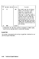


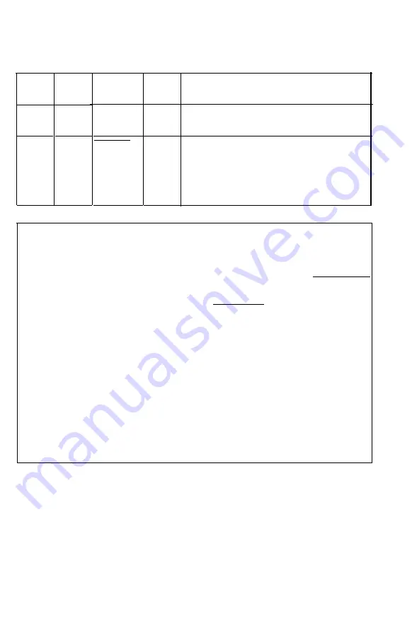
Signal
Pin
Signal
3.5
--
36
Return
Pin
-
-
+ 5 v
SLCTIN
Direction
IN
Description
Pulled up to 5V through 3.3K ohm
resistance.
The DC 1/DC3 control codes are valid
only when this signal
IS
HIGH (SLCTIN
set to OFF). This setting can be changed
with SelecType. Sampling
IS
carried out
only when the power
IS
on.
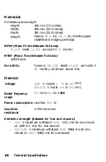
Notes:
•
All interface conditions are based on TTL level. Both the rise
and fall of each signal must be less than
0.2
microseconds.
l
Data transfer must be carried out by observing the ACKNLG
or BUSY signal. (Data transfer to this printer
can
be carried
out only after the receipt of the ACKNLG signal or when
the level of the BUSY signal is LOW.
l
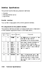
The column heading “Direction” refers to the direction of
signal flow as viewed from the printer.
•
“Return” denotes the twisted-pair return to be connected at
signal ground level. For the interface wiring, be sure to use a
twisted-pair cable for
each
signal and to complete
the
connection on the return side. These cables should be
shielded and connected to the chassis of the host computer
and the printer.
8-12
Technical Specifications
Summary of Contents for EPL-7500
Page 1: ......
Page 3: ......
Page 52: ...Testing the Printer 2 12 Testing and Connecting Your Printer ...
Page 237: ...V Ventilation grill 6 15 W Weight paper 8 4 printer 8 8 Index IN 5 ...
Page 242: ......
Page 243: ......
Page 244: ......


