background image

EPSON TERMINAL PRINTER

EPL-N1200

SERVICE MANUAL

EPSON

4006838

Summary of Contents for EPL-N1200

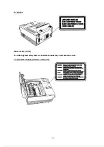
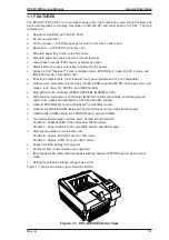
Page 1: ...EPSON TERMINAL PRINTER EPL N1200 SERVICE MANUAL EPSON 4006838 ...

Page 2: ...s manual However should any errors be detected SEIKO EPSON would greatly appreciate being informed of them The above notwithstanding SEIKO EPSON can assume no responsibility for any errors in this manual or the consequence thereof Epson is a registered trademark of Seiko Epson Corporation General Notice Other product names used herein are for identication purposes only and may be trademarks of the...

Page 3: ...MANUAL DO NOT CON NECT THE UNIT TO A POWER SOURCE UNTIL INSTRUCTED TO DO SO WHEN THE POWER SUPPLY CABLE MUST BE CONNECTED USE EXTREME CAUTION IN WORKING ON POWER SUPPLY AND OTHER ELECTRONIC COMPONENTS WA FINING REPAIRS ON EPSON PRODUCT SHOULD BE PERFORMED ONLY BY AN EPSON CERTIFIED REPAIR TECHNICIAN MARE CERTAIN THAT THE SOURCE VOLTAGE IS THE SAME AS THE RATED VOLTAGE LISTED ON THE SERIAL NUMBER R...

Page 4: ...ry for products marketed in the United States The label shown below indicates compliance with the CDRH regulations and must be attached to laser products marketed in the United States WARNING Use of controls adjustments or performance of procedures other than those specified in this manual may result in hazardous radiation exposure Internal Laser Radiation Maximum Radiation Power 5 0x lO QW Wave L...

Page 5: ...RNING Osynlig laserstr lning nar denna de1 3r oppnad och spirren Hr urkopplad Betrakta ei strblen For Norway Users 1 ADVARSEL Dersom apparatet brukes pa annen mate enn spesifisert i denne bruksan visning kan brukeren utsettes for unsynlig laserstr ng som over rider gren sen for laser klasse 1 Dette er en halvleder laser Maksimal effeckt til laserdiode er 5 0 x lo4 W o bolgelengde er 790 f 20 run I...

Page 6: ...For Europe Label inside printer The following laser safely label will be attached inside the printer as shown below For Denmark Finland Sweden and Norway ...

Page 7: ...f the printer CHAPTER 2 OPERATING PRINCIPLES Describes the theory of printer operation CHAPTER 3 DISASSEMBLY AND ASSEMBLY Includes a step by step guide for product disassembly and assembly CHAPTER 4 ADJUSTMENTS Includes a step by step guide for adjustment CHAPTER 5 TROUBLESHOOTING Provides Epson approved techniques for adjustment CHAPTER 6 MAINTENANCE Describes preventive maintenance techniques an...

Page 8: ...REVISION SHEET I Revision I Issue Date Revision Page Rev A December 9 1996 1st issue vii ...

Page 9: ...TABLE OF CONTENTS CHAPTER 1 CHAPTER 2 CHAPTER 3 CHAPTER 4 CHAPTER 5 CHAPTER 6 APPENDIX GENERAL DESCRIPTION OPERATING PRINCIPLES DISASSEMBLY AND ASSEMBLY ADJUSTMENTS TROUBLESHOOTING MAINTENANCE VIII ...

Page 10: ...ns 1 11 1 3 INTERFACE SPECIFICATIONS 1 12 1 3 1 Parallel Interfaces 1 12 1 3 1 1 Compatibility Standard Mode 1 12 1 3 1 2 Nibble Reverse ECP Mode 1 14 1 3 2 Optional Serial Interface LocalTalk Serial Module 1 18 1 4 OPERATING INSTRUCTIONS 1 22 1 4 1 Control Panel 1 22 1 4 2 SelecType Functions 1 24 1 4 3 Service Mode 1 29 1 4 3 1 Hexadecimal Dump Mode 1 29 1 4 3 2 EEPROM Format 1 29 1 4 3 3 Error ...

Page 11: ...Data Transfer Timing Chart 1 16 Figure 1 7 Termination Timing Chart 1 17 Figure 1 8 Interrupt Timing Chart 1 17 Figure 1 9 Control Panel 1 22 Figure 1 10 Multi Port and Multi Emulation 1 34 Figure 1 11 Emulation Switch by SPL 1 35 Figure 1 12 Intelligent Emulation Switch 1 35 Figure 1 13 BiRITech Effect 1 36 Figure 1 14 RITech Adjustment 1 36 Figure 1 15 Toner Save Mode 1 38 Figure 1 16 Component ...

Page 12: ... Built in Fonts 1 7 Table 1 8 Parallel Interface Pin Assignment 1 13 Table 1 9 Parallel Interface Pin Assignment 1 14 Table 1 10 Serial Interface Pin Assignments 1 19 Table 1 11 LocalTalk Interface Pin Assignments 1 21 Table 1 12 SelecType Functions 1 27 Table 1 13 Main Controller Board Default Paper Size Setting 1 29 Table 1 14 Status Messages 1 31 Table 1 15 Error Messages 1 32 Table 1 16 Warnin...

Page 13: ...d I239X modes o High performance controller 20 MHz SPARKlite MB86930 CPU o Bi Resolution Improvement Technology BiRITech refines print quality eliminating jagged edges from images and characters on 600 and 300 DPI printing o Optional EPSONScript Level 2 PostScript compatible module o Optional LocalTalk Serial Module and Type B interfaces can be used simultaneously o 2 MB standard RAM and up to 64 ...

Page 14: ...S051016 Imaging cartridge Toner cartridge C82334 LocalTalk Serial Module C83620 RS 232C intrerface cable 9 pin For C82334 C83619 RS 232C intrerface cable 25 pin For C82334 C83618 Current loop cable For C82334 C82307 C82308 32 KB serial interface card C82310 C82311 32 KB parallel interface card C82312 LocalTalk interface card C82314 COAX interface card C82315 TWINAX interface card C82323 GPIB inter...

Page 15: ...e of 16 to 24 lb 60 to 90 g m2 paper Lower paper cassette optional 1 500 3 A4 or LT 2 16 to 24 lb 60 to 90 g m2 1 Two units maximum can be mounted 2 Paper size is fixed either A4 or Letter 3 70g m 2 20lb paper 4 When you set pieces of paper on standard paper tray 5 When you set a piece of paper on standard paper tray 6 It can be used as manual feeding paper slot Note 1 The weight in pounds lb is d...

Page 16: ...irection Center alignment for all sizes Paper ejection Face down Output tray capacity 250 sheets standard paper 20 lb 75g m 2 Printable area standard paper See Figure 1 2 Note The actual printable area depends on the printer mode Harmonic noise Less than 36 dB A standby Less than 52 dB A operating Ozone density Less than 0 02 PPM Toxicity No toxicity exists in organic photo conductor OPC toner and...

Page 17: ...ndard paper 30 mm 1 2 inches or less OHP sheet Leading edge bending 1 cm or more 1 out of 1 000 sheets MTTR Mean Time To Repair 30 minutes or less Durability 5 years or 300 000 sheets 1 2 4 Environmental Conditions for Operating Including Imaging Cartridge Temperature 10 to 35 C 50 to 95 F Humidity 15 to 85 RH Altitude 2 500m 8 200 feet or lower Levelness 1 degree or less front to rear right to le...

Page 18: ...onal Energy Star Program standard 1 2 7 Specification for Consumable Imaging Cartridge Life 6 000 pages Note In continuous print mode with A4 letter paper at a 5 image black white ratio ratio L life varies depending on print mode continuous or intermittent and or image ratio Environmental Conditions for Storage and Transportation Temperature 0 t o 3 0 C 32 to 86 F overfull storage period Humidity ...

Page 19: ...cType setting Available in PCL Switch to PCL ESC A Not supported Supported Reset ESC E Ejects paper and then initializes Ejects paper switches to PCL and then initializes PJL EJL and ES Supported Supported Advance Full Page PG AF Supported Not supported Notes EPSON GL 2 mode has two operational modes One is LJ4 GL 2 mode the other is the GL like mode LJ4 GL 2 mode emulates the GL 2 mode in the HP ...

Page 20: ...edium Italic SWC V Swiss 742 Bold Italic SWC V Swiss 742 Condensed SWC V Swiss 742 Bold Condensed SWC V Swiss 742 Condensed Italic SWC V Swiss 742 Bold Italic Condensed SWC V Incised 901 SWC V Incised 901 Black SWC V Incised 901 Italic SWC V Original Garamond SWC V Original Garamond Bold SWC V Original Garamond Italic SWC V Original Garamond Bold Italic SWC V Audrey Two SWC V Flareserif 821 SWC V ...

Page 21: ...SC P 2 FX I239X Courier SWC V V V V Courier Bold SWC V V V V Courier Italic SWC V Courier Bold Italic SWC V Letter Gothic Roman SWC V V V Letter Gothic Bold SWC V V V Letter Gothic Italic SWC V Ext Graph V V V V Supported Not supported EPL N1200 Service Manual General Description Rev A 1 9 ...

Page 22: ...ows PsText IBM US IBM DN McText PcMultilingual VeInternational VeUS PiFont PcE Europe Symbol WiAnsi TWingdings MsPublishing VeMathRIBM SPanish ESC P 2 Mode 15 International characters and 9 code tables USA SPAIN1 FRANCE JAPAN GERMANY NORWAY UK DENMARK2 DENMARK1 SPAIN2 SWEDEN L AMERICA ITALY KOREA TLEGAL PcUSA 437 PcMultilingual 850 TPcPortuguese 860 TPcCanFrench 863 PcNordic 865 T PcTurk2 857 PcE ...

Page 23: ...s A4 or letter Second Lower Paper Cassette 16 seconds or less A4 or letter Feeding Speed subsequent sheets 12 PPM A4 Letter Paper Type Plain paper such as copier paper Power Supply 5 V DCand 24 VDC are supplied by the printer Dimensions and Weight Width Depth Height Lower paper cassette entire housing 405 477 107 mm 18 8 19 0 4 2 inches 2 8 Kg 6 2 lb Paper Cassette 252 318 82 mm 9 9 12 5 3 2 inche...

Page 24: ...r type Amphenol or equivalent IEEE 1284B type connector Parallel Interface C Interface specification complies with IEEE 1284 II Operating modes Compatibility standard nibble reverse and ECP modes Transfer speed APPROX 2MB second in ECP mode MAX Connector type IEEE 1284C type connector 1 3 1 1 Compatibility Standard Mode System STROBE synchronization 8 bit parallel data transfer Handshaking BUSY an...

Page 25: ...SY O 1 BUSY O The BUSY signal informs the host computer of the printer state When the signal is HIGH the printer cannot accept data 12 PE O 5 PE O The PE signal indicates paper empty for the standard tray selected through SelecType or command or for the optional paper cassette Paper empty is indicated by HIGH 13 SLCT O 2 SLCT O Use at reverse mode 14 AUTO FEED I 17 AUTO FEED I Not used 15 18 34 NC...

Page 26: ... clock 11 BUSY OUT PtrBusy Printer sending data bits 3 and 7 during data transfer to host computer 12 PE OUT AckDataReq Printer sending data bits 2 and 6 during data transfer to host computer 13 SLCT OUT Xflag Printer sending data bits 2 and 6 during data transfer to host computer 14 AUTO FEED IN HostBusy This signal informs the printer of the host computer state When the signal is HIGH the host c...

Page 27: ...tion Reverse Data Transfer Host Busy Data Available Host Busy Data Not Available ERR HIGH No data sent ERR LOW Sending data ERR LOW Sending data ERR HIGH AUTO FEED LOW No data sent Request to send data Reverse Idle Interrupt Host SLCT IN LOW ERR LOW AUTO FEED LOW AUTO FEED HIGH Figure 1 4 Parallel Interface State Switch Diagram EPL N1200 Service Manual General Description Rev A 1 15 ...

Page 28: ...ion request value was 04h Note 3 HB DA Host Busy Data Available HB DNA Host Busy Data Not Available DATA SEL IN STROBE AUTO FEED ACKNLG Peripheral Busy Status BUSY PE SLCT ERROR HB DA Negotiation HB DA or HB DNA Note 3 Idle or Transfer Bit 3 Bit 7 Bit 2 Bit 6 Bit 1 Bit 5 Bit 0 Bit 4 Peripheral Busy Status Note 1 Note 1 Note 2 Figure 1 6 Data Transfer Timing Chart DATA 00h or 04h SEL IN STROBE AUTO...

Page 29: ...equest value was 04h DATA SEL IN STROBE AUTO FEED ACKNLG Peripheral Busy Status BUSY PE SLCT ERROR Reverse Idle Interrupt Note 1 HB DA Transfer Figure 1 8 Interrupt Timing Chart DATA SEL IN STROBE AUTO FEED ACKNLG Peripheral Busy Status BUSY PE SLCT ERROR HB DNA Idle or HB DA Termination Compatibility Peripheral Busy Status Note 1 Note 2 Note 3 Current Peripheral Status Current Peripheral Status N...

Page 30: ...gnal level speeds of 2400 BPS and above place restrictions on the host computer cable and other operationg conditions Error Overrun error Processed as missing data and replaced by Parity error Replaced by Framing error Replaced by Breaking character Ignored Applicable plug Circular miniature DIN 8 pin plug Signal Level EIA BASED TXD DTR Out put Voltage VOH 5 to 15 V VOL 5 to 15 V Open circuit volt...

Page 31: ...logic 1 is at LOW level MARK TTY TXD return Refer to TTY TXD 4 GND GND Ground 5 RXD I TTY RXD return RXD Serial ASCII data input to the printer It maintains MARK state LOW level between received character codes TTY TXD return Refer to TTX RXD 6 N C TTY TXD O TTY TXD Serial ASCII data output from the printer The logic is determined by the impedance between pins 3 and 6 Logic 0 is high impedance SPA...

Page 32: ...H When SelecType is used to set the DTR control OFF DTR is always set HIGH The printer transmits TXD only when DSR is at the HIGH level DSR is always considered HIGH when the SelecType setting for DSR is OFF X ON X OFF transmission is independent of the DSR state o X ON X OFF DC1 DC3 protocol SelecType is used to execute the X ON X OFF protocol The X OFF DC3 code is output if status indicates an e...

Page 33: ...IGH the RXD signal can be received by the printer 2 CTS I The printer transmits the data through TXD while CTS is HIGH 3 TXD O Serial ASCII data output from the printer HIGH level when SD voltage is higher than SD voltage LOW level when SD voltage is less than SD voltage Logic 0 SPACE and logic 1 MARK must be maintained between transmitted character codes 4 GND Ground 5 RXD I Serial ASCII data inp...

Page 34: ...When the printer is off line and the Form Feed light is lit pressing this button prints data in the printer s memory o Continue Pressing this button when the Continue light is flashing clears an error o SelecType Selects one of three modes OneTouch menu 1 OneTouch menu 2 or SelecType mode o Menu Selects one of three menus Paper Source RITech or SelecType o Value Selects one of three menus Manual F...

Page 35: ...is state occurs when the system cannot shift from off line to on line or vice versa o Form Feed This LED indicates the data processing condition for each interface channel ON Received data stored in the printer but has not been printed OFF No printable data remains in the printer Flashing The printer is processing data o Continue Flashes when an error is detected or a maintenance procedure is need...

Page 36: ...ource Resident SIMM Download Font Number 0 to available MAX 65535 Pitch 0 44 to 10 00 to 99 99 CPI step 0 01 Height 4 00 to 12 00 to 999 75 PT step 0 25 SymSet Roman 8 ECM94 1 8859 2 ISO 8859 9 ISO IBM US IBM DN PcMultiling PcE Europe PcTk437 WiAnsi WiE Europe WiTurkish DeskTop PsText VeInternati VeUS MsPublishin Math 8 PsMath VeMath PiFont Legal UK ANSI ASCII Swedis2 Italian Spanish German Norweg...

Page 37: ...gin 0 40 to 0 50 to 1 50 Inch step 0 05 Text 1 to 62 3 to 66 2 to Available 81 MAX Lines CG Table Italic PcUSA PcMultilin PcPortugues PcCanFrenc PcNordic PcTurkish2 Pc E Europe BpBRASCII BpAbicomp Country USA France Germany UK Denmak Sweden Italy Spain1 Japan Norway Denmark2 Spain2 LatinAmeric Auto CR On Off Auto LF Off On Bit Image Dark Light BarCode Zero Char 0 φ I239X Menu Font Courier Prestige...

Page 38: ... LC2 Size 8 12 A4 LT Config Menu RITech 0 Medium Dark Off Light Toner Save Off On Density 3 4 5 1 2 Top Offset 9 0 to 0 0 to 99 0 mm Left Offset 9 0 to 0 0 to 99 0 mm Size Ignore Off On Auto Cont Off On Page Protect Auto On Image Optimum Auto Off On Setup Menu Interface Auto ParallelB ParallelC Serial 6 L T 5 AUX 10 Time Out 0 5 to 60 to 300 Standby Enable Disable Lang 18 English Lang 18 Francais ...

Page 39: ...Off Robst DTR On Off Buffer Size 21 Normal Maximum Minimum L T Menu 5 Buffer Size 21 Normal Maximum Minimum AUX Menu 10 Buffer Size 21 Normal Maximum Minimum JOB PAGE PROTECT OFF LT LGL A4 RESOLUTION 300 600 TIMEOUT 5 to 300 1 GL 2 menu doesn t have it 2 Factory setting for Europe and Taiwan 3 Factory setting for North America 4 Can be selected only when EPSONScript Level 2 ROM Module is installed...

Page 40: ...d only when content information data exists 15 Internally always set to OFF It is not displayed on the LCD as a setting item 17 This item is not displayed on the LCD 18 Setting Item Lang is displayed for a language setting value for both setting the item and the value 21 After resetting the value warm boot or restart the printer to make the value effective General Description EPL N1200 Service Man...

Page 41: ...r size A4 or letter toner counter page counter jam counter and panel settings are all stored in memory Default Factory Setting Defaults for EEPROM format functions can be written to EEPROM as follows Turn on the printer while holding down the On Line Reset and Menu buttons until Format Nvram is displayed This function Clears the page counter Clears the paper jamcounter Writes the factory default s...

Page 42: ...cType Menu Item Value and Enter buttons Displays the detailed information for the fatal error code This function let you know the meaning of the error status E or C2XXX in details 1 Press the Continue SelecType and Menu buttons 2 The printer diplays ERR YXXXX 0X 3 Press any button 4 The printer diplays ERR TYPE 0X 5 Press any button then return to 2 6 Printing SysErr desplays and you can print an ...

Page 43: ...omes valid when a reset or warm boot is performed Status Form Feed Paper form feeding Status Warming up Warming up Status Standby Power down mode Status Ready Normal condition Status Menus Locked This message is valid when Panel Lock is set to on by EJL command Press any button Warning Chack Paper Size This message is valid when Size Ignore is off Paper size is different from the page size you are...

Page 44: ... terminated Replace the imaging cartridge Press the Continue button clear the error temporarily Paper Set XXXXX YYYY The paper in the selected tray is different from the paper size selection When Auto Cont is off Load proper paper in the correct paper tray Press the Continue button without replacing paper When Auto Cont is on The error is automatically cleared Print Overrun Engine speed is faster ...

Page 45: ...indicate that setting values can t be saved in EEPROM Press any button to release this warning Check Paper Size Paper in the selected tray is different from the paper size chosen with Size Ignore Off Press the Continue button Image Optimum Because of insufficient memory the printer uses a lower print quality Increase memory size Press the Continue button Toner Low Remaining toner is 0 Replace the ...

Page 46: ...Talk Serial Module and Type B I F card can be used simultaneously Note 2 Selection of one of two interfaces for the LocalTalk Serial Module is determined by the type of cable and jumper settings on the module Jumper settings for the module are recognized when the printer is powered on Note3 Installation of a Type B I F card is recognized when the printer is powered on Figure 1 10 Multi port and Mu...

Page 47: ... precise specifications for this language are based on the HP LaserJet 4 The figure below shows three types of mode switching Neither EJL nor PJL switches the mode directly They first exit the current mode and return to EJL or PJL Then they enter another mode 1 4 6 2 Intelligent Emulation Switch The Intelligent Emulation Switch IES automatically switches the emulation switch mode depending on the ...

Page 48: ...ns or gray scales In such cases BiRITech must be set to OFF The default setting is MEDIUM Since the BiRITech effect depends on the toner condition it should be adjusted when the imaging cartridge is replaced or after the imaging cartridge is used for a long time The following settings are available in SelecType Level for RITech DARK MEDIUM LIGHT OFF When the toner density of area A is almost the s...

Page 49: ...ort up to the point of the reset is lost 3 Errors are canceled Warm Boot Procedure This is performed by holding down the Alt and Reset buttons for several seconds The worm boot procedure aborts printing on all interfaces and performs the reset 1 Initialization of memory 2 The data input buffers for all interfaces are cleared Cold Start Procedure This is performed by turning the power switch is on ...

Page 50: ...rd The printer s controller board comes with 2 MB of RAM installed By installing additional SIMMs you can increase the printer s memory to a total of 64 MB including the resident memory EPSON supplies several types of memory option SIMMs Other SIMMs can be purchased from other vendors Be sure the SIMM meets the requirements listed below 72 pin type Capacity is one of the following 1 2 4 8 16 32 MB...

Page 51: ...rcuit board C173 PROG Board 1 Program ROM circuit board Control panel Unit PWB A Board Engine controller circuit board PU1 Board Power supply circuit board HV1 Board High voltage supply circuit board Optical Unit Printhead unit Fusing Unit Imaging Cartridge Lower Paper Cassette Unit optional Only for specific models Figure 1 16 Component Layout EPL N1200 Service Manual General Description Rev A 1 ...

Page 52: ...ASIC E05A91 IC1 ASIC E05A93 IC11 ASIC E05B17 IC16 ASIC E05B27 IC43 ASIC E05B31 IC38 Other Reset IC 953B IC2 There are two types of C205 MAIN boards used as after service parts The following table shows differences between them Table 1 17 Differences in Components for the C205 MAIN Board For USA For Others Standard Paper Size Letter Size Paper A4 Size Paper Jumper J4 Setting Open Pin 1 and Pin 2 Cl...

Page 53: ... bus interface communicating with C205 Main board 1 5 3 Control Panel The control panel includes a 20 column 1 row LCD panel which provides many functions for the printer e g displaying error messages or printer operation status 4M bit Flash ROM IC1 2 3 4 Figure 1 18 C173 PROG Board Figure 1 19 Control Panel EPL N1200 Service Manual General Description Rev A 1 41 ...

Page 54: ...oard consists of a switching regulator circuit It converts the AC line voltage into 24 V and 5 VDC voltages There are two types of power supply board the 100 120 V type and 230 V type The difference between the two circuits is only in the input section CAUTION Do not touch VR1 and VR61 on the power supply board These volumes are for factory setting only M37451 IC1 Figure 1 20 Engine Controller Boa...

Page 55: ...it consists of the laser diode semi conductor laser the mirror motor scanner motor which drives the polygon mirror for laser scanning and several mirrors and lenses The laser beam generated by the laser diode is conducted to the OPC drum surface by way of the polygon mirror as well as several mirrors and lenses to create a latent electro photographic image on the drum Figure 1 22 High Voltage Supp...

Page 56: ... fusing units the 100 120 V type and the 230 V type The only difference between them is the heater lamp 1 5 9 Imaging Cartridge The core mechanisms of the printing process such as charging developing and cleaning are integrated into this imaging cartridge Figure 1 24 Fusing Unit Figure 1 25 Imaging Cartridge General Description EPL N1200 Service Manual 1 44 Rev A ...

Page 57: ...r cassette allows you to feed up to an additional 500 sheets of A4 or letter size paper into this printer You can add the two lower papaer cassettes for the printer Figure 1 26 Lower Paper Cassette EPL N1200 Service Manual General Description Rev A 1 45 ...

Page 58: ...2 2 Fuser Control 2 11 2 1 2 3 Scanner Mirror Motor Control 2 13 2 1 2 4 Laser Diode Drive 2 13 2 1 2 5 Bias Voltages and Laser Drive Timing 2 14 2 1 2 6 Power Supply Circuit Function and Safety Protection 2 16 2 2 VIDEO CONTROLLER OPERATION 2 17 2 2 1 C205 MAIN Board Operation 2 17 2 2 1 1 Reset Circuit 2 20 2 2 1 2 Bus Control Circuit 2 19 2 2 1 3 Interrupt Control 2 21 2 2 1 4 DRAM Management 2...

Page 59: ...e 2 12 Figure 2 18 Scanner Motor Control Circuit 2 13 Figure 2 19 Laser Diode Drive Circuit 2 13 Figure 2 20 L DATA Generation Circuit 2 13 Figure 2 21 High Voltage Supply Block Diagram 2 14 Figure 2 22 Print Process 2 15 Figure 2 23 Print Sequence Start 2 15 Figure 2 24 Print Sequence End 2 15 Figure 2 25 Power Supply Circuit Block Diagram 2 16 Figure 2 26 Video Controller Section 2 17 Figure 2 2...

Page 60: ...p Roller 20 Transfer Roller 6 Heater Lamp H1 21 Paper Take up Roller 7 Thermostat 22 Paper Empty Sensor Lever 8 Paper Exit Roller 23 2nd Lower Paper Cassette Unit Option 9 Upper Fusing Roller 24 1st Lower Paper Cassette Unit Option 10 Paper Exit Sensor Lever 25 Power Supply Unit PU1 11 Paper Exit Sensor PC3 26 Multi Purpose Paper Tray 12 Lower Fusing Roller 13 Image Transfer Roller 14 Cooling Fan ...

Page 61: ...ocess This section describes the print process from paper feeding to paper exit Figure 2 2 shows a diagram of the print process Figure 2 2 Print Process Diagram Operating Principles EPL N1200 Service Manual 2 2 Rev A ...

Page 62: ... causes the signal to go HIGH informing the engine driver that paper has been detected The paper exit sensor is located beyond the fusing roller in the paper path When paper passes the paper exit sensor the detection lever is lowered allowing light from the LED to reach the photo transistor This causes the signal to go HIGH informing the engine driver that paper has been delivered Multi Purpose Tr...

Page 63: ...ricity before laser exposure This printer uses a brush charge method rather than the corona charge method to charge the drum In the brush charge method there is no generation of ozone as a result of corona discharge This method also allows the drum to be charged at a low voltage because a direct electric load is applied to the PC drum Lower Paper Cassette up to two units Connector to 2nd Lower Pap...

Page 64: ...oner to the invisible static electric image The doctor blade spreads a thin even coat of toner over the flexible sleeve When the toner passes between the doctor blade and the flexible sleeve it becomes negatively charged The flexible sleeve transports toner to the surface of the PC drum and controls the development with the developing bias voltage No positively charged toner is transported to the ...

Page 65: ...ransfer roller The drum charge bias voltage is used 2 1 1 7 Fusing Fusing is the process of fixing the toner image transferred during the image transfer process onto the paper This printer uses the heating roller method for fusing The heating roller method fixes the toner image with an upper fusing roller that is heated by the heater lamp The thermistor TH1 detects the temperature of the upper fus...

Page 66: ...by the reflective mirror Then the photo sensor receives the light and the controller recognizes a toner empty condition When you open and close the top cover after the printer has detected a toner empty signal the controller assumes that the imaging cartridge has been replaced and resets the toner empty status Toner is enough Toner is empty Figure 2 10 Toner is Enough Reflective Mirror Photo Senso...

Page 67: ... AC Power Input Interlock SW Heater Lamp Main Motor Power Supply Board PU1 PWB D LD SOS Mirror Scanner Motor Control Panel Main Controller Board C205 MAIN Lower Paper Cassette 1 option Paper Empty Sensor Cassette Detecting SW Paper Take Up Solenoid SL2 Engine Controller Board PWB A Doctor Blade Bias Charge Brush Development Fan Motor PWB G Toner Empty Sensor Lower Paper Cassette 2 option Paper Emp...

Page 68: ...ssette optional feeding drive Figures 2 13 and 2 14 show the positions of the gears and rollers 0 Main Motor M1 4 PC Drum 10 Paper Take up Roller 11 Transport Roller 13 Upper Fusing Roller 15 Paper Exit Roller 21 Image Transfer Roller Figure 2 13 Gears and Rollers 1 29 28 27 30 31 20 18 28 29 19 27 30 31 18 10 5 6 11 9 0 1 2 3 12 16 13 15 14 21 8 4 7 25 26 20 EPL N1200 Service Manual Operating Pri...

Page 69: ... 14 4 43 30 P C Drum 20 22 17 5 47 21 16 Image Transfer Roller 6 41 29 25 39 7 28 26 24 26 17 8 23 27 18 9 40 16 28 18 10 69 46 Paper Take Up Roller 29 28 11 23 Transport Roller 30 18 12 66 18 31 14 13 40 Upper Fusing Roller 14 35 15 14 13 0 1 2 3 21 4 8 26 15 11 10 9 5 7 6 5 1 12 16 18 9 Figure 2 14 Gear and Roller Positions Operating Principles EPL N1200 Service Manual 2 10 Rev A ...

Page 70: ...o the heater lamp This AC voltage is cut by the interlock switch when the top cover opens The fuser temperature is detected by the thermistor Based on the TH1 signal from the thermistor the engine controller board PWB A controls the fusing temperature using the FUSER LAMP signal A TdA TdB CN10A 2 3 4 5 5 4 3 2 CN3PU1 B 24V B A 24V A CN5PU1 1 2 3 4 5 6 Main Motor M1 Power Supply Board PU1 Engine Co...

Page 71: ...00 C 212 F or more at the printer power on the fusing temperature is controlled keep the roller at 175 C 347 F during standby and 200 C 392 F during printing Envelope Mode When the printer encounters paper smaller than the exective paper such as an envelope in the standard MP tray the fusing temperature is controlled to keep the roller at 175 C 347 F during standby and 200 C 392 F during printing ...

Page 72: ...he VIDEO or the FORCED LASER DIODE ON signal is activated LOW the L DATA signal will be active The VIDEO signal is an image signal sent from the video controller board C205 MAIN board The FORCED LASER DIODE ON signal is a laser emission signal to apply the laser beam to the SOS sensor 24V GND2 POLYGON MOTOR PORYGON LOCK PORYGON CLOCK 5 4 3 2 1 CN5A Engine Controller Board PWB A Scanner Motor M2 M ...

Page 73: ...his signal controls the bias voltage level 175 V to 375 VDC using analog data The image density is controlled by the developing bias voltage level There is a three position slide switch on the PWB S board The switch can select one of three image transfer bias current values The standard position is M If the printer is used in an environment with high temperature and high humidity and an image tran...

Page 74: ...Drum Image Transfer Development Figure 2 22 Print Process 4 09 0 8 074 0 255 0 26 Print Main Motor On sec Drum Charge CH1 Laser Exposure LD Development DB Image Transfer CH1 0 3 Paper Loading Sensor PC2 On Paper Take up Solenoid SL1 0 5 0 5 Figure 2 23 Print Sequence Start 0 65 0 15 Main Motor Off sec Drum Charge CH1 Laser Exposure LD Development DB Image Transfer CH1 Paper Loading Sensor PC2 Off ...

Page 75: ...age supply main motor M1 drive scanner mirror motor M2 drive fan motor M3 drive and solenoid drive For safety protection the 24 VDC line is cut when the interlock switch cover open switch is off AC IN Interlock SW 24 VDC GND2 GND1 5 VDC Power Supply Board PU1 Figure 2 25 Power Supply Circuit Block Diagram Operating Principles EPL N1200 Service Manual 2 16 Rev A ...

Page 76: ... MB86930 SPARKlite 20 MHz 32 bit bus RISC CPU the standard cells developed for this printer RAMs ROMs and a EEPROM C205 MAIN Board Video Controller Section Engine Controller Board PWB A Control Panel Figure 2 26 Video Controller Section ROM 16M Bits Code IC32 33 ROM 16M Bits Font IC12 13 EEPROM IC5 RAM SIMM CN1 CN6 E05A91 IC 1 Serial LT Module RS 232C RS 422 or LocalTalk DRAMs IC 18 19 20 21 Addre...

Page 77: ...lTalk I F board interface Type B interface card control Control panel control E05B17 ASIC IC16 This ASIC contains the following functions BiRITech E05B27 ASIC IC43 This ASIC contains the following functions Parallel C interface Two 8 M bit ROMs IC12 13 These ROMs are code ROM Two 8M bit ROMs IC32 33 These ROMs are font ROM Option 8M Bit ROM IC6 This ROM is a local language ROM option for fonts EEP...

Page 78: ...r can increase the V RAM by using SelecType setting Page Protect The E05A91 transmits image data stored in the V RAM to E05B17 The E05B17 changes the image data format from 32 bits parallel data to serial data and stores it in the internal temporary buffer The temporary buffer has a capacity equivalent to several lines This is controlled by the E05B17 which synchronizes and transmits the temporary...

Page 79: ... Circuit The MB86930 CPU outputs the R W read write signal AS address strobe signal and the BE0 BE1 BE2 and BE3 signals byte enables to the ASIC E05A91 The ASIC E05A91 uses these signals to generate the RD read strobe signal WR write strobe signal and READY signal 5V Vcc C OUT 5V M51953B IC2 RESET RSTOUT RSTIN E05B31 IC38 Figure 2 29 Reset Circuit R W AS BE0 3 RD WR READY Data Bus Address Bus CPU ...

Page 80: ...es DRAMs for the system RAM and for the V RAM In this printer four standard 512K 8bit DRAMs are mounted in locations IC18 IC19 IC20 and IC21 providing a total of 2 MB SIMM sockets number 1 CN1 and number 2 CN6 are optional SIMM sockets These SIMM sockets can use 1 2 4 8 16 32 MB SIMM 32 bit bus The DRAMs including optional SIMMs are managed by the ASIC E05A91 which also outputs MA0 10 memory addre...

Page 81: ...interface circuit block diagram The 74ACT1284 is a bi directional bus driver IC that used to satisfy the data bus length under the IEEE1284 standard The E05B27 IC43 is used the Parallel C interface to support not only standard parallel interface but also compatibility mode and bi directional mode Nibble and ECP under the IEEE1284 standard Latch STROBE BUSY DATA E05A93 IC11 Latch Figure 2 32 Parall...

Page 82: ...d can be broadly divided into four groups The first group PRINT CPRDY EPRDY and PRDY gives the status of either the video controller or engine controller and indicates whether they are ready to communicate with each other or ready to start the printing operation The second group VSYNC HSYNC is the synchronizing signal for the printing operation The third group VIDEO is the serial video data signal...

Page 83: ...rd Removal 3 7 3 2 2 2 Power Supply Unit Removal 3 8 3 2 2 3 Interlock Switch Removal 3 11 3 2 2 4 Optical Unit Removal 3 12 3 2 2 5 Paper Empty Sensor Removal 3 13 3 2 2 6 Toner End Sensor Removal 3 14 3 2 2 7 Paper Take Up Solenoid Removal 3 15 3 2 2 8 High Voltage Supply Board Removal 3 16 3 2 2 9 Main Motor Removal 3 18 3 2 2 10 Paper Take Up Sensor Removal 3 19 3 2 2 11 Fan Motor Removal 3 20...

Page 84: ...moval 3 15 Figure 3 19 Fusing Unit Cover Removal 3 16 Figure 3 20 Rear Panel Unit Removal 3 16 Figure 3 21 High Voltage Supply Board Removal 3 17 Figure 3 22 Main Motor Removal 3 18 Figure 3 23 Paper Take Up Sensor Removal 3 19 Figure 3 24 Fan Motor Removal 3 20 Figure 3 25 Fusing Unit Removal 3 21 Figure 3 26 Paper Exit Sensor Removal 3 21 Figure 3 27 Fusing Unit Removal 1 3 22 Figure 3 28 Fusing...

Page 85: ...m the printer do not place it in direct sunlight Do not disassemble the optical unit Never turn power on if the optical unit is not installed To prevent damage to ICs from static electricity do not touch the ICs on the circuit board or the terminals of peripheral electrical components with your hands Use only the recommended tools to ensure safe and efficient maintenance work Inappropriate tools m...

Page 86: ...s recessed Pan head CC Cross recessed Cup head CP O Cross recessed Pan head with Outside toothed lock washer CP S P1 Cross recessed Pan head with Spring lock washer and 1 Plain washer CCB Cross recessed Cup head Bind SCB Slotted Cross recessed B tight SCB S P1 Slotted Cross recessed Bind with Spring washer and 1 Plain washer Table 3 3 Screw Types and Abbreviations Disassembly and Assembly EPL N120...

Page 87: ... modes Adjustment Print position Does the J4 on the main controller board match for the specific standard paper size A4 size paper of letter size paper ROM version Status sheet or C205 MAIN board Is it the latest ROM version Cleaning Is toner and dust removed from the paper path Is the lens on the optical unit cleaned Is the paper take up roller cleaned Is the rollers in the fusing unit cleaned Is...

Page 88: ...d the control panel unit 3 2 1 1 Main Controller Board C205 MAIN Board Removal CAUTION Before you remove the main controller board make sure that you remove any optional cards or cartridges Otherwise you may damage the cartridge or card connectors on the board as well as the cartridge or card itself 1 Turn the printer so that its back side faces you 2 Remove the four thumbscrews M3 14 3 3 Pull the...

Page 89: ... 4 Remove two CC M3x8 screws and take the right cover away 5 Remove two CC M3x8 screws on the paper guide case 6 Remove four CC M3x6 screws on the top and two CC M3x6 screws at the right of the shield cover and take it away 7 Remove connector CN3 on the engine controller board 8 Remove the control panel CC M3X6 CC M3X6 Figure 3 4 Shield Cover Removal CC M3X6 CC M3X8 CC M3X8 Control Panel Paper Gui...

Page 90: ...CN3 Figure 3 5 Connectors on Engine Driver Board Disassembly and Assembly EPL N1200 Service Manual 3 6 Rev A ...

Page 91: ...anel and lift the panel forward 4 Remove two CC M3x8 screws and take the right cover away 5 Remove two CC M3x8 screws on the paper guide case 6 Remove four CC M3x6 screws on the top and two CC M3x6 screws at the right of the shield cover and take it away 7 Remove all connectors CN2 CN3 CN4 CN5 CN6 CN7 CN9 and CN10 on the engine controller board 8 Remove four CC M3x6 screws on the engine controller...

Page 92: ...power supply board shield cover and take the PS unit shield cover away 7 Remove two CP O M3x8 screws which secure the power supply unit frame and release two fooks from the bottom frame Then remove the power supply unit frame by pulling it forward 8 Remove all connectors on the power supply board CN1 CN2 CN3 CN4 CN5 CN6 blue socket and white socket cables on the power supply board 9 Remove four CC...

Page 93: ...ower Supply Unit Figure 3 9 Power Supply Unit Removal 1 CC M3X6 CC M3X6 CC M3X6 CC M3X6 Blue White CN1 CN5 CN3 CN2 CN4 CN6 Figure 3 10 Power Supply Unit Removal 2 EPL N1200 Service Manual Disassembly and Assembly Rev A 3 9 ...

Page 94: ...t into the printer insert the tabs on the power supply unit frame into the holes in the bottom frame correctly Power Supply Unit Frame Bottom Base Frame Figure 3 11 Power Supply Unit Installation Disassembly and Assembly EPL N1200 Service Manual 3 10 Rev A ...

Page 95: ...ft the panel forward 4 Remove two CC M3x8 screws and take the right cover away 5 Remove two CC M3x8 screws on the paper guide case 6 Remove four CC M3x6 screws on the top and two CC M3x6 screws at the right of the shield cover and take it away 7 Remove two CP S P M3x16 screws 8 Remove two cables orange and red from the interlock switch CC M3x16 Orange Wire Red Wire Interlock Switch Figure 3 12 Int...

Page 96: ...move one CC M3 6 screw from the control panel and lift the panel forward 4 Remove two CC M3x8 screws and take the right cover away 5 Remove two CC M3x8 screws on the paper guide case 6 Remove four CC M3x6 screws on the top and two CC M3x6 screws at the right of the shield cover and take it away 7 Remove connector CN5 on the engine controller board 8 Remove one CC M3x6 screw on the right frame whic...

Page 97: ...al unit Refer to Section 3 2 2 4 3 Disconnect tabs for the paper empty sensor and remove the paper empty sensor 4 Disconnect connector for the paper empty sensor CC M3x14 CC M3x6 Engine Controller Board B A A B CC M3x6 CN5 Figure 3 14 Optical Unit removal Paper Empty Sensor Connector Figure 3 15 Paper Empty Sensor Removal EPL N1200 Service Manual Disassembly and Assembly Rev A 3 13 ...

Page 98: ...light or place it in a dark area 2 Remove the optical unit Refer to Section 3 2 2 4 3 Disconnect tabs for the toner end sensor and remove the toner end sensor 4 Disconnect connector for the toner end sensor Toner End Sensor Connector Figure 3 16 Toner End Sensor Removal Disassembly and Assembly EPL N1200 Service Manual 3 14 Rev A ...

Page 99: ... cover 4 Remove the bracket which mounted the toner empty sensor 5 Disconnect the cable for the paper take up solenoid from the base unit 6 Remove one CC M3 6 screw from the paper take up solenoid and remove the paper take up solenoid Bracket CC M3X6 CC M3X6 Roller Cover Figure 3 17 Bracket Removal Paper Take up Solenoid Connector CC M3X6 Figure 3 18 Paper Take up Solenoid Removal EPL N1200 Servic...

Page 100: ...w on the fusing unit cover and remove the fusing unit cover 6 Remove four CP O M3x6 screws on the rear panel unit 7 7 Disconnect connector from the paper exit sensor then lay the rear panel unit flat 8 Remove connectors CN1 CN2 CN3 the red wire terminal and the black wire terminal on the high voltage supply board 9 Remove three CP B M3 6 screws on the high voltage supply board then remove the high...

Page 101: ...Black Wire Red Wire CP B M3X8 CP B M3X8 CP B M3X8 CN3 CN1 CN2 Figure 3 21 High Voltage Supply Board Removal EPL N1200 Service Manual Disassembly and Assembly Rev A 3 17 ...

Page 102: ...fusing unit cover 6 Remove four CP O M3x6 screws on the rear panel unit 7 Disconnect connector for the paper exit sensor then lay the rear panel unit flat 8 Remove one CC M3 6 screw from the control panel and lift the panel forward 9 Remove two CC M3x8 screws on the paper guide case 10 10 Remove four CC M3x6 screws on the top and two CC M3x6 screws at the right of the shield cover and take it away...

Page 103: ...2 Remove the high voltage supply board Refer to Section 3 2 2 8 3 Remove the main motor Refer to Section 3 2 2 9 4 Remove the sensor lever 5 Remove the paper take up sensor 6 Disconnect connector for the paper take up sensor Sensor Lever Connector Paper Take up Sensor Figure 3 23 Paper Take up Sensor Removal EPL N1200 Service Manual Disassembly and Assembly Rev A 3 19 ...

Page 104: ...eft and right tabs of the top cover from the printer base unit then remove the top cover 5 Remove one CC M3x6 screw on the fusing unit cover and remove the fusing unit cover 6 Disconnect connector for the paper exit sensor then lay the rear panel unit flat 7 Disconnect connector for the fan motor 8 Remove two CCB M3x8 screws then remove the fan motor CCB M3X8 Fan Motor Paper Exit Sensor Connector ...

Page 105: ... fusing unit cover and remove the fusing unit cover 6 Disconnect two connectors for the thermistor and the fusing unit lamp 7 Remove two CP O M3x6 screws on the fusing unit then remove the fusing unit 3 2 2 13 Paper Exit Sensor Removal 1 Remove the fusing unit Refer to Section 3 2 2 12 2 Remove the paper exit sensor 3 Disconnect the paper exit sensor from connector of the cable Connector for Therm...

Page 106: ...es of the fusing unit cover then remove both sides of the fusing unit cover 3 Remove the fusing lamp CAUTION Do not touch the glass surface of the lamp with your bare hands CCB M3X8 CCB M3X8 Figure 3 27 Fusing Unit Removal 1 Fusing Lamp Figure 3 28 Fusing Unit Removal 2 Disassembly and Assembly EPL N1200 Service Manual 3 22 Rev A ...

Page 107: ...using unit into two parts 6 Remove one CC M3 10 screw then remove the Thermistor 7 Remove two CS P M3x6 screws then remove the thermostat CAUTION Do not touch the glass surface of the lamp with your bare hands The thermistor and thermostat must be attached at the fusing roller The connector for the thermistor must be inserted firmly CC M3X6 Figure 3 29 Fusing Unit Disassembly Thermistor CC M3X10 T...

Page 108: ... the left lift up the right side and remove the image transfer assembly 4 Remove the image transfer Roller CAUTION Do not touch the surface of the image transfer roller with your bare hands Figure 3 31 Image Transfer Assembly Removal Figure 3 32 Image Transfer Roller Assembly Construction Disassembly and Assembly EPL N1200 Service Manual 3 24 Rev A ...

Page 109: ...mounts the toner empty sensor 7 Disconnect connectors CN1 CN2 CN3 the red wire terminal and the black wire terminal on the high voltage supply board 8 Remove two CC M3 8 screws on the paper pick unit 9 Slide the paper pick unit to the left lift the left side up and remove the paper pick unit 11 Remove one E ring on the paper take up clutch and remove the paper take up clutch 12 Remove two E rings ...

Page 110: ...Figure 3 35 Paper Pick Assy Removal Figure 3 36 Paper Take Up Roller Removal Disassembly and Assembly EPL N1200 Service Manual 3 26 Rev A ...

Page 111: ...Chapter 4 Adjustment No adjustment is required in this product ...

Page 112: ...CD Displays Paper Jam during Paper Feeding 5 5 Table 5 12 The LCD Displays Mem Overflow 5 6 Table 5 13 The LCD Displays SERVICE REQ E0003 5 6 Table 5 14 Main Motor doesn t rotate correctly 5 7 Table 5 15 The LCD Displays SERVICE REQ E0005 5 7 Table 5 16 The LCD Displays SERVICE REQ E0006 5 7 Table 5 17 The LCD Displays SERVICE REQ E0009 5 8 Table 5 18 The LCD Displays SERVICE REQ E0014 5 8 Table 5...

Page 113: ... reserved Main Contropller Error C0002 CPU error privilege violation C0003 CPU error illegal instruction C0004 CPU error no support FPU instruction C0007 CPU error address misalignment C0009 CPU error reserved C0010 CPU error tag overflow C0017 to 31 CPU error no support interrupt C0036 CPU error no support coprocessor instruction C0128 to 254 CPU error unimplemented instruction C0255 CPU error br...

Page 114: ...d Jam when using the lower paper cassette 5 9 Paper Jam The LCD displays Paper Jam at power on 5 10 Paper Jam displayed during paper feeding The LCD displays Paper Jam during paper feeding 5 11 Mem Overflow The LCD displays Mem Overflow 5 12 SERVICE REQ E0003 The LCD displays SERVICE REQ E0003 5 13 Main motor doesn t rotate correctly 5 14 SERVICE REQ E0005 The LCD displays SERVICE REQ E0005 5 15 S...

Page 115: ...roller board C205 MAIN board may be dead 1 If you change the C205 MAIN board does the printer start the RAM check Yes Replace the C205 MAIN board The control panel may be dead 2 Replace the control panel Table 5 5 The LCD Displays Printer Open Cause Step Checkpoint Finding Solution The interlock switch terminal connector may be disconnected 1 Is interlock switch terminal connector disconnected Yes...

Page 116: ... shorted 2 Disconnect connector CN6 on the engine controller board and check coil resistance between pin 4 and pin 5 on the disconnected cable side of the connector using a multimeter Is the resistance approximately 82 ohms No Replace the paper take up solenoid If the coil is shorted check the solenoid drive circuit using the procedure below 1 Set the multimeter for voltage range 2 Place the termi...

Page 117: ...er take up sensor flag The paper exit sensor flag position may be incorrect 2 Is the paper exit sensor flag position OK No Reposition the paper exit sensor flag The paper take up sensor connector may be disconnected 3 Is the paper take up sensor connector disconnected Yes Connect it The paper exit sensor connector may be disconnected 4 Is the paper exit sensor connector disconnected Yes Connect it...

Page 118: ...nnector for the thermistor may be disconnected 1 Is the connector for the thermistor disconnected Yes Connect it The engine controller board may be dead 2 Does the heater lamp remain lit up until an error occurs Yes Replace the engine controller board The heater lamp or thermal fuse in fusing unit may be bad 3 Does the heater lamp come on at power on No Replace the heater lamp or thermal fuse in f...

Page 119: ...rminal of the multimeter on pins 1 3 4 or 6 of connector CN5 on the power supply board 3 Place the terminal on pin 2 of connector CN7 of the power supply board GND With power on does the multimeter detect voltage Yes Replace the power supply board The power supply board may be dead 2 Replace the power supply board Table 5 15 The LCD Displays SERVICE REQ E0005 Cause Step Checkpoint Finding Solution...

Page 120: ...he C205 MAIN board Table 5 20 The LCD Displays SERVICE REQ C1000 1001 1002 Cause Step Checkpoint Finding Solution The C205 MAIN board may be bad 2 Replace the C205 MAIN board Table 5 21 The LCD Displays SERVICE REQ C1003 Cause Step Checkpoint Finding Solution The optional SIMM may be bad 1 Is operation OK after you remove the optional SIMM Yes Replace the SIMM The C205 MAIN board may be bad 2 Repl...

Page 121: ...ing Solution The optional ROM SIMM board may be bad 1 Is operation OK after you replace the ROM SIMM Replace the optional ROM SIMM board The C205 MAIN board may be bad 2 Replace the C205 MAIN board Table 5 26 The LCD Displays SERVICE REQ C12XX Cause Step Checkpoint Finding Solution The EEPROM IC5 on the C205 MAIN board may be bad 1 Replace the EEPROM IC5 on the C205 MAIN board The C205 MAIN board ...

Page 122: ...transfer roller is damaged Replace the image transfer roller HV1 board Replace the HV1 board Paper problem Paper Check to see if paper is moist Replace paper Defective optical unit Optical unit Replace the optical unit Improper print density setting Adjust the print density using SelecType Foggy background Poor development Imaging cartridge Replace the imaging cartridge Check the wiring of develop...

Page 123: ...harging Imaging cartridge Replace the imaging cartridge HV1 board Replace the HV1 board Poor development Imaging cartridge Replace the imaging cartridge HV1 board Replace the HV1 board Improper setting of the print density Adjust the print density by SelecType Defective optical unit Optical unit Replace the optical unit White black lines and bands Improper charging Imaging cartridge Shake the imag...

Page 124: ...oard Poor development Imaging cartridge Shake the imaging cartridge Replace the imaging cartridge Poor development HV1 board Replace the HV1 board Paper problem Paper Check to see if paper is moist Replace the paper Toner smudges on back side of pages Smears on paper path Image transfer roller Check the surface of image transfer roller Clean the image transfer roller Fusing roller Clean the fusing...

Page 125: ... cartridge Shake the imaging cartridge Replace the imaging cartridge HV1 board Replace the HV1 board Defective PC drum Imaging cartridge Replace the imaging cartridge Left side printing missing Top cover isn t closed properly Top cover Close the top cover correctly ABCDE ABCDE ABCDE ABCDE EPL N1200 Service Manual Troubleshooting Rev A 5 13 ...

Page 126: ...rvice Maintenance 6 3 6 1 2 2 Cleaning 6 3 List of Figures Figure 6 1 External Cleaning 6 1 Figure 6 2 Optical Unit Lens Cleaning 6 1 Figure 6 3 Imaging Cartridge Removal 6 2 Figure 6 4 Imaging Cartridge Shaking 6 2 Figure 6 5 Clear Seal Removal 6 2 Figure 6 6 Imaging Cartridge Insertion 6 2 List of Tables Table 6 1 Periodic Service Maintenance 6 3 Table 6 2 Cleaning Parts and Procedures 6 3 ...

Page 127: ...6 ii Rev A ...

Page 128: ... repair 6 1 1 User Maintenance Users can achieve maximum print quality from the printer by following the procedures below 6 1 1 1 Cleaning This section describes the cleaning required for optimal print quality External Cleaning Be sure to disconnect the printer from the power outlet before cleaning it Wipe the cover and external parts of the printer with a damp cloth that has been soaked in a neut...

Page 129: ...spose of the used imaging cartridge 3 While holding the new imaging cartridge horizontally gently shake it a few times to distribute the toner evenly 4 Set the imaging cartridge on a clean flat surface Firmly grip the tab on the left side of the cartridge Pull the clear seal all the way out with firm even pressure as shown 5 Shake the imaging cartridge again 6 Insert the imaging cartridge into the...

Page 130: ...e value You do not need to perform service maintenance exactly at this time 6 1 2 2 Cleaning Some parts of this printer require regular cleaning For example whenever the paper jams during paper loading or when print quality problem happen Clean each part using the specified method and tools Refer to Chapter 3 for disassembly procedures Table 6 2 Cleaning Parts and Procedures Parts Name Cleaning Pr...

Page 131: ... Board Component Layout Front Side A 17 Figure A 5 C205 MAIN Board Component Layout Rear Side A 18 List of Tables Table A 1 Board Connector Summary A 3 Table A 2 CN1 and 6 Pin Assignments A 4 Table A 3 CN2 Pin Assignments A 6 Table A 4 CN3 Pin Assignments A 7 Table A 5 CN4 Pin Assignments A 9 Table A 6 CN7 Pin Assignments A 10 Table A 7 CN11 Pin Assignments A 11 Table A 8 CN4 Pin Assignments A 13 ...

Page 132: ...ves the size and a description of each connector CN6 RAM SIMM SLOT CN1 RAM SIMM SLOT CN3 ROM SIMM SLOT CN4 C82334 SLOT CN9 PARALLEL C CN7 TYPE B I F BOARD SLOT CN2 PWB A CN8 PARALLEL B CN11 C173 PROG BOARD C205 MAIN BOARD Figure A 1 Video Controller Section Cable Connection EPL N1200 Service Manual Appendix A Rev A A 1 ...

Page 133: ...Figure A 2 Engine Section Cable Connection Appendix A EPL N1200 Service Manual A 2 Rev A ...

Page 134: ...A 8 CN5 Connector for optical unit 13 pins Table A 9 CN6 Connector for paper take up solenoid paper exit sensor and paper empty sensor 8 pins Table A 10 CN7 Connector for high voltage supply board 8 pins Table A 11 CN8 Connector for power supply board 8 pins Table A 12 CN9 Connector for lower paper cassette 12 pins Table A 13 CN10 Connector for power supply board 6 pins Table A 14 Control Panel CN...

Page 135: ...t 3 16 A4 O Memory address bit 4 17 A5 O Memory address bit 5 18 A6 O Memory address bit 6 19 A10 O Memory address bit 10 20 DQ4 I O Data bus bit 4 21 DQ20 I O Data bus bit 20 22 DQ5 I O Data bus bit 5 23 DQ21 I O Data bus bit 21 24 DQ6 I O Data bus bit 6 25 DQ22 I O Data bus bit 22 26 DQ7 I O Data bus bit 7 27 DQ23 I O Data bus bit 23 28 A7 O Memory address bit 7 31 A8 O Memory address bit 8 32 A...

Page 136: ...Data bus bit 26 55 DQ11 I O Data bus bit 11 56 DQ27 I O Data bus bit 27 57 DQ12 I O Data bus bit 12 58 DQ28 I O Data bus bit 28 60 DQ29 I O Data bus bit 29 61 DQ13 I O Data bus bit 13 62 DQ30 I O Data bus bit 30 63 DQ14 I O Data bus bit 14 64 DQ31 I O Data bus bit 31 65 DQ15 I O Data bus bit 15 67 PD1 Not used 68 PD2 Not used 69 PD3 Not used 70 PD4 Not used EPL N1200 Service Manual Appendix A Rev ...

Page 137: ... 7 19 GND Ground 20 RESETX O Reset signal 21 GND Ground 22 NC Not connected 23 GND Ground 24 HSYNCX I HSYNC for Main I F 25 EPRDYX I Engine controller ready 26 PRDYX I Print ready 27 TODX I Main request 28 ETBSYX I Engine controller busy 29 STSX I Status transfer 30 CMDX O Command transfer 31 CTBSYX O Main controller busy 32 PRINITX O Print signal 33 SRCLKX O Serial transfer clock 34 CPRDYX O Main...

Page 138: ...ory address bit 10 20 D4 I O Data bus bit 4 21 D20 I O Data bus bit 20 22 D5 I O Data bus bit 5 23 D21 I O Data bus bit 21 24 D6 I O Data bus bit 6 25 D22 I O Data bus bit 22 26 D7 I O Data bus bit 7 27 D23 I O Data bus bit 23 28 A7 O Memory address bit 7 29 A19 O Memory address bit 19 31 A8 O Memory address bit 8 32 A9 O Memory address bit 9 33 A20 O Memory address bit 20 34 EEP O 5 VDC 35 RESET ...

Page 139: ... bit 11 56 D27 I O Data bus bit 27 57 D12 I O Data bus bit 12 58 D28 I O Data bus bit 28 60 D29 I O Data bus bit 29 61 D13 I O Data bus bit 13 62 D30 I O Data bus bit 30 63 D14 I O Data bus bit 14 64 D31 I O Data bus bit 31 65 D15 I O Data bus bit 15 66 A16 O Memory address bit 16 67 R B Not used 68 NC O Write signal 69 70 NC Not used 70 PO4 Not used 71 A15 O Memory address bit 15 Appendix A EPL N...

Page 140: ... I O Data bus bit 4 12 DB5 I O Data bus bit 5 13 DB6 I O Data bus bit 6 14 DB7 I O Data bus bit 7 15 AB0 O Address bus bit 0 16 AB1 O Address bus bit 1 17 AB2 O Address bus bit 2 18 AB3 O Address bus bit 3 19 AB4 O Address bus bit 4 20 CS O Chip select signal 21 RD O Read signal 22 WR O Write signal 23 IREQ O Address bus bit 13 24 NMI O Address bus bit 14 25 DREQ O Address bus bit 11 26 DTCT O Add...

Page 141: ...I I F ready 15 RDREQ I Data read request 16 WR O Write signal 17 RD O Read signal 18 CS O Chip select signal 25 A3 O Address bus bit 3 26 A2 O Addres bus bit 2 27 A1 O Addres bus bit 1 28 A0 O Addres bus bit 0 29 D7 I O Data bus bit 7 30 D6 I O Data bus bit 6 31 D5 I O Data bus bit 5 32 D4 I O Data bus bit 4 33 D3 I O Data bus bit 3 34 D2 I O Data bus bit 2 35 D1 I O Data bus bit 1 36 D0 I O Data ...

Page 142: ...Data bus bit 23 22 D24 I O Data bus bit 24 24 D25 I O Data bus bit 25 26 D26 I O Data bus bit 26 28 D27 I O Data bus bit 27 30 D28 I O Data bus bit 28 32 D29 I O Data bus bit 29 34 D30 I O Data bus bit 30 36 D31 I O Data bus bit 31 49 A0 O Address bus bit 0 50 A1 O Address bus bit 1 51 A2 O Address bus bit 2 52 A3 O Address bus bit 3 53 A4 O Address bus bit 4 54 A5 O Address bus bit 5 55 A6 O Addr...

Page 143: ...ignal 75 76 VPP 5 V DC 1 2 3 4 VCC 5 V DC 37 38 77 78 79 80 VSS Ground 39 CSI0 O Chip select inable 0 40 CSI1 O Chip select inable 1 41 CSO0 Not used 42 CSO1 Not used 43 RD O Read signal 44 WR O Write signal 45 BWE0 O Bus write enable 0 46 BWE2 O Bus write enable 1 47 BWE1 O Bus write enable 2 48 BWE3 O Bus write enable 3 Appendix A EPL N1200 Service Manual A 12 Rev A ...

Page 144: ...LDVR2 O Laser power adjust 2 11 LDLVL I Laser power signal 12 SSCAN I Horizontal synchronous signal 13 GND1 Ground Table A 10 CN6 Pin Assignments Pin No Signal Name I O Description 1 ANODE 5 VDC 2 GND1 Ground 3 PS3 I Paper exit signal 4 24V 24 VDC 5 PICK UP1 Paper take up solenoid trigger 6 ANODE I 5 VDC 7 GND1 Ground 8 P EMP1 O Paper empty sensor signal Table A 11 CN7 Pin Assignments Pin No Signa...

Page 145: ... signal 1 6 PSIZE21 I Paper size signal 2 7 PSIZE22 I Paper size signal 3 8 PICK UP2 O Paper take up solenoid 2 9 PREFED2 O Paper feed 2 10 PICK UP3 O Paper take up solenoid 3 11 PREFED3 I Paper feed 3 12 BIN SELECT I Lower paer cassette select Table A 14 CN10 Pin Assignments Pin No Signal Name I O Description 1 FAN MOTOR O Fan motor On 2 OB M1 phase B 3 OA O M1 phase A 4 TdA O Reference A 5 TdB R...

Page 146: ... Signal Name I O Description 1 B O Main motor phase B 2 24V 24 VDC 3 B O Main motor phase B 4 A O Main motor phase A 5 24V 24 VDC 6 A O Main motor phase A A 1 4 High Voltage Supply Board HV1 Board Table A 17 CN2 Pin Assignments Pin No Signal Name I O Description 1 ANODE O LED power 2 GND1 Ground 3 PS1 II Paper take up signal EPL N1200 Service Manual Appendix A Rev A A 15 ...

Page 147: ...2 CIRCUIT DIAGRAM Figure A 3 C205 MAIN Board Circuit Diagram Appendix A EPL N1200 Service Manual A 16 Rev A ...

Page 148: ...A 3 CIRCUIT BOARD COMPONENT LAYOUT Figure A 4 C205 Main Board Component Layout Front EPL N1200 Service Manual Appendix A Rev A A 17 ...

Page 149: ...Figure A 5 C205 Main Board Component Layout Rear Appendix A EPL N1200 Service Manual A 18 Rev A ...

Reviews: