


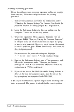


Disabling an existing password
If you do not know your power-on password and do not want to
set
a
new one, follow these steps to disable the existing
password:
1.
Turn off the computer and follow the instructions under
“Changing the Jumper Settings” in Chapter 5 to disable the
password function by setting jumper JP13 to position A.
2.
Insert the Reference diskette in drive A and turn on the
computer. You do not see the key prompt.
3.
When the Operation Menu appears, highlight Set up
and press
Enter.
Then see “Setting the Power-on Password”
in Chapter 2 and follow the instructions as if you are going
to enter a new password. However, when you see the prompt
to enter a password, press
Enter
immediately. This clears out
the existing password.
Be sure to save the password setting and highlight
* * EXIT AND SAVE
* * when you leave Setup.
4.
Remove the Reference diskette, turn off the computer, and
follow the instructions under “Changing the Jumper
Settings” in Chapter 5 to enable the password function by
setting jumper JP13 to position A.
5.
If you do not have a hard disk, insert the Startup diskette in
drive A. Turn on the computer again. You do not see the
key prompt and the computer loads MS-DOS.
Later, if you want to create a power-on password, run Setup and
enter a password. The jumper is already in the correct position.
D-10 Troubleshooting
Summary of Contents for Equity 386/25
Page 1: ......
Page 3: ......
Page 14: ...xii ...
Page 20: ...6 lntroduction ...
Page 63: ...Hard disk drive types continued Running the Setup Program 2 25 ...
Page 142: ...5 34 lnstalling and Removing Options ...
Page 248: ...C 14 Physically Formatting a Hard Disk ...
Page 298: ...F 6 Specifications ...
Page 326: ......


