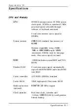
background image

Controllers

Diskette

Hard disk

Interfaces

Monitor

Serial

Parallel

Mouse port

Keyboard

Option slots

Supports up to two drives in any of four

formats: 5 

 high-density, 1.2MB;

 double-density, 360KB;

 high-density, 1.44MB; or

 double-density, 720KB;

controller on main system board

Supports up to two half-height drives;
embedded controller; interface on main
system board

VGA adapter with 512KB DRAM (video
memory) built into main system board;
supports up to 800 

600 pixels in 16-colors

or up to 640 x 480 pixels in 256-colors;

multi-frequency monitor required for
resolutions over 640 x 480

15-pin, D-shell connector

RS-232C, programmable, asynchronous;

9-pin, D-shell connector

Standard 8-bit parallel, mono-directional;
25-pin, D-shell connector

Mini DIN, 6-pin connector for PS/2
compatible mouse or other device

Mini DIN, 6-pin connector for PS/2

compatible keyboard

Four standard input/output expansion slots

(three 16-bit ISA compatible and one

8-bit ISA compatible); 8 MHz bus speed

Summary of Contents for EQUITY 3865X/20 PLUS

Page 1: ...EPSON E Q U I T Y 3 8 6 5 X 2 0 P L U S U s e r s G u i d e ...

Page 2: ...EPSON E Q U I T Y 3 8 6 S X 2 0 P L U S USER S GUIDE X EQ386 20PLUS ...

Page 3: ...it different from that to which the receiver is connected l Consult the dealer or an experienced radio TV technician for help WARNING The connection of a non shielded equipment interface cable to this equipment will invalidate the FCC Certification of this device and may cause interference levels which exceed the limits established by the FCC for this equipment It is the responsibility of the user...

Page 4: ...recording or otherwise without the prior written permission of Epson America Inc No patent liability is assumed with respect to the use of information contained herein While every precaution has been taken in the preparation of this publication Epson America assumes no responsibility for errors or omissions Nor is any liability assumed for damages resulting from the use of the information containe...

Page 5: ... radiator or heat register This product should not be placed in a built in installation unless proper ventilation is provided 7 This product should be operated from the type of power source indicated on the marking label If you are not sure of the type of power available consult your dealer or local power company 8 This product is equipped with a 3 wire grounding type plug a plug having a third gr...

Page 6: ...uct from the wall outlet and refer servicing to qualified service personnel under the following conditions A When the power cord or plug is damaged or frayed B If liquid has been spilled into the product C If the product has been exposed to rain or water D If the product does not operate normally when the operating instructions are followed Adjust only those controls that are covered by the operat...

Page 7: ...1 4 Using the VGA Interface 1 4 Using a Display Adapter Card 1 7 Connecting a Printer or Other Device 1 8 Using the Parallel Interface 1 8 Using the Serial Interface 1 11 Connecting the Keyboard 1 12 Connecting the Mouse 1 13 Connecting the Power Cord 1 15 Turning On the Computer 1 16 Turning Off the Computer 1 18 Chapter 2 Running the Setup Program Automatic Configuration 2 2 Starting the Setup P...

Page 8: ...r 3 Using Your Computer Installing MS DOS or Another Operating System 3 1 Copying the Reference Diskette Files 3 2 Special Keys on the Keyboard 3 3 Stopping a Command or Program 3 5 Resetting the Computer 3 5 Using a Power on Password 3 7 Changing a Power on Password 3 8 Deleting a Power on Password 3 9 Using Disks and Disk Drives 3 10 How Disks Store Data 3 10 Types of Diskette Drives 3 12 Caring...

Page 9: ...Memory Beyond 640KB 4 11 Using Special VGA Features 4 12 Chapter 5 Accessing Internal Components Removing the Cover 5 2 Removing the Subassembly 5 5 Replacing the Subassembly 5 8 Replacing the Cover 5 16 Chapter 6 Installing and Removing Options Changing the Jumper Settings 6 2 Moving a Jumper 6 4 Installing an Option Card 6 5 Removing an Option Card 6 9 Adding Memory Modules 6 10 Installing Memor...

Page 10: ...sition Installing or Removing a Disk Drive in the Horizontal Position Installing a Disk Drive in the Horizontal Position Removing a Disk Drive From the Horizontal Position Appendix A Troubleshooting 7 2 7 3 7 4 7 4 7 5 7 7 7 8 7 10 7 12 7 19 7 21 7 23 7 24 7 33 Identifying Your System A 1 Error Messages A 2 The Computer Won t Start A 5 The Computer Does Not Respond A 6 Password Problems A 8 Removi...

Page 11: ...4 Selecting an Option B 4 Starting the Formatting Process B 4 Option 1 Format B 5 Modifying the Defective Track Table B 7 Formatting the Disk B 9 Option 2 Destructive Surface Analysis B 10 Option 3 Non destructive Surface Analysis B 12 Exiting the Hard Disk Format Menu B 13 Appendix C Performing System Diagnostics Starting System Diagnostics Selecting an Option Modifying the Device List Selecting ...

Page 12: ...Appendix D Specifications CPU and Memory D 1 Controllers D 2 Interfaces D 2 Power Supply D 3 Mass Storage D 3 Keyboard D 4 Environmental Requirements D 4 Physical Characteristics D 5 Glossary Index x ...

Page 13: ...on slots three 16 bit and one 8 bit inside the computer Your system can support up to three internal drives either two diskette drives and one hard disk drive or one diskette drive and two hard disk drives The Equity 3865X 20 PLUS offers several other features to enhance its speed and versatility Memory caching Portions of your system memory are copied to a high speed cache buffer so your computer...

Page 14: ...and adding optional devices compatible with the IBM Personal Computer PC XT or PC AT By adding memory modules to the main system board you can expand the computer s memory up to 14MB Memory modules are efficient because your computer can access memory on modules faster than memory on an option card Also they eliminate the need to use an option slot to add memory to your system If necessary you can...

Page 15: ...ually any application program designed for the IBM PC PC XT PC AT or compatible computers on your Equity 386SX 20 PLUS You may also use powerful software such as Microsoft Windows 386 VGA Utilities Epson has provided special VGA utilities and device drivers that you can use with certain standard VGA and multi frequency monitors With these drivers you can use super VGA features such as 16 color gra...

Page 16: ...or setting up your system On the back cover foldout are illustrations showing the different parts of your computer refer to these as you set up your system Chapter 2 describes how to run the Setup program to define your computer s configuration Do this before you use your computer You may need to do it again later if you change the configuration Chapter 3 provides instructions for important operat...

Page 17: ...o Get Help Customer support and service for Epson products are provided by a network of authorized Epson dealers and Customer Care Centers throughout the United States Epson America provides product information and support to its dealers and Customer Care Centers Therefore we ask that you contact the business where you purchased your Epson product to request assistance If the people there do not h...

Page 18: ...ou may want to leave this manual s back cover foldout open so you can refer to the illustrations identifying the different parts Note The illustrations in this manual show the computer with a 51 4 inch diskette drive If your system has a 3 i z inch diskette drive instead and you need additional instructions see Chapter 3 1 Choosing a Location Setting Up Your System 1 1 ...

Page 19: ...circulation Air must be able to move freely under the system and behind it Leave several inches of space around the computer Moderate environmental conditions Protect your computer from extremes in temperature humidity dust and smoke Avoid direct sunlight or any other source of heat High humidity also hinders operation so select a cool dry area Appropriate power sources To prevent static charges c...

Page 20: ... it flip the latch up to pop the card out part way then pull it out as shown below If you have a second Y 4 inch diskette drive be sure to remove the protector card from that drive as well Save the protector card If you transport your computer you may want to insert the card into your diskette drive prior to shipping This will protect the read write heads during transportation Setting Up Your Syst...

Page 21: ...ou have any other type of monitor see Using a Display Adapter Card below Using the VGA Interface Follow these steps to connect your VGA monitor to the VGA port on the computer 1 Make sure your monitor is turned off 2 Place your monitor on top of or near the computer For easy access turn the monitor and computer around so the backs of both components are facing you 3 If necessary connect the monito...

Page 22: ... insert the plug into the port the connector should fit in easily when properly oriented as shown below retaining screws Caution To avoid damaging the connector take care not to bend the pins when inserting the plug 5 If the connector has retaining screws tighten them by hand or with a screwdriver depending on the screw type Setting Up Your System 1 5 ...

Page 23: ...6 If necessary plug the monitor power cord into the monitor s power inlet as shown below Q II J II I 7 Plug the other end of the power cord into an electrical outlet 1 6 Setting Up Your System ...

Page 24: ...tor are properly matched Monitor video card compatibility Monitor Monochrome Video card Monochrome display adapter MDA Multi mode graphics adapter MGA Enhanced graphics adapter EGA Hercules graphics card Color or EGA Color graphics adapter CGA Multi mode graphics adapter MGA Enhanced graphics adapter EGA l CGA monitors do not support EGA modes When you are installing the video card check to make s...

Page 25: ...he computer If your monitor came with its own manual follow the instructions there Otherwise you can follow the steps in Using the VGA Interface above just insert your monitor connector into the video card port instead of the built in VGA port 4Connecting a Printer or Other Device Your computer has both parallel and serial interfaces To connect a printer or other peripheral device to one of these ...

Page 26: ... end of the printer cable has a 25 pin D shell connector Position the plug to match the orientation of the parallel interface marked with a special icon Then insert the connector into the port as shown below If the plug has retaining screws tighten them by hand or with a screwdriver depending on the screw type i retaining screws Setting Up Your System 1 9 ...

Page 27: ...e to the printer as shown below TO secure the cable squeeze the clips at each side of the printer port and push them into place clips 4 Plug the printer s power cord into a 120 volt grounded electrical outlet 1 10 Setting Up Your System ...

Page 28: ... above for connecting a parallel device but insert the connector into the serial port marked with a special icon as shown below serial port Note You need to ensure that the serial port is set up so it functions properly If you are using the port for a serial printer you need to redirect printer output to the serial port instead of the parallel port To do this you can use the MS DOS MODE or SETMODE...

Page 29: ...ng faces up Insert the plug into the appropriate socket marked with a keyboard icon as shown below I w r T keyboard connector arrow indicator Caution Although the keyboard and mouse connectors are physically identical they cannot be used interchangeably Be sure to insert the keyboard plug into the keyboard socket 1 12 Setting Up Your System ...

Page 30: ...r or adapter you can connect it to the built in port on your computer If you purchased a mouse with a serial connector you can connect it to the built in serial port on your computer If you have another kind of mouse that requires a different interface port you need to install an option card to provide the interface To connect a mouse to the built in mouse port hold the mouse plug so it is oriente...

Page 31: ...ably Be sure to insert the mouse plug into the mouse port Once you have connected a mouse you may need to add commands to your MS DOS CONFIG SYS and AUTOEXEC BAT files to enable your computer to use a mouse See your MS DOS Reference Manual and the manual that came with your mouse for instructions 1 1 4 Setting Up Your System ...

Page 32: ... cord into the AC power inlet on the back panel as shown below WARNING To avoid an electric shock be sure to plug the cord into the computer before plugging it into the wall socket 2 Plug the other end of the power cord into a 120 volt grounded electrical outlet Setting Up Your System 1 15 ...

Page 33: ...f and on rapidly can damage the computer s circuitry Do not leave a beverage on top of or next to your system or any of its components Spilled liquid can damage the circuitry of your equipment Always turn off the power disconnect the computer s power cord and wait five seconds before you remove the cover Only remove the cover to access optional devices or change jumper settings Follow these steps ...

Page 34: ...nds the computer starts to perform a diagnostic self test a series of checks it completes each time you turn it on to make sure everything is working correctly Note If you or your dealer have made a major change to your system such as adding a disk drive you may need to wait as long as five minutes for your computer to complete power on diagnostics the first time you turn it on The more extensive ...

Page 35: ...re clear and at a comfortable level of intensity If your monitor has horizontal and vertical hold controls you may need to use them to stabilize the display Turning Off the Computer When you are ready to turn off your system reverse the sequence of steps you followed to turn it on Turn off the computer first then turn off the monitor and any peripherals Now go on to Chapter 2 and follow the instru...

Page 36: ...puter Display adapter type Power on password Memory caching Processor speed Keyboard and speaker options Real time clock s time and date Hard disk drive configuration Diskette drive type s Serial and parallel port settings The configuration you define with the Setup program is stored in the computer s CMOS RAM which is backed up by a battery Whenever you turn on the computer it searches the CMOS R...

Page 37: ...to verify that the settings are correct for your configuration The computer automatically configures the 2MB of memory that comes with your system as 640KB of base memory and 1280KB of extended memory If you install even more memory Setup configures it as extended memory also Starting the Setup Program Follow these steps to start the Setup program 1 Make sure your computer is turned off 2 Insert t...

Page 38: ...en displays the Operation Menu OPERATION MENU 1 Setup 2 Format hard disk 3 System diagnostics 4 Prepare hard disk for moving 0 Exit to DOS for more utilities If an error message appears when you turn on the computer see continuing From an Error Message below 4 The Setup option is highlighted To select it press Enter The screen displays the main Setup menu Exit Display Password Cache memory Process...

Page 39: ...error message beside the diamond indicates the condition causing the error There may be more than one error listed in the message Here are some of the error messages you may see Time is invalid HDD and or HDC failed initialization Memory size is incorrect correction made Cacheable range is adjusted Incorrect configuration Checksum is incorrect HDD is incorrect Some errors such as Time is invalid d...

Page 40: ...they are correct for your system The default value for the setting that caused the error may not be the correct one for your configuration Note If you choose N or press ESC instead of selecting Y to set a default value the Setup program does not change the setting that caused the error and the screen displays the main Setup menu Be sure to correct this setting before you exit Setup Moving the Curs...

Page 41: ...d a VGA monitor to the built in VGA port Setup automatically sets the display adapter type With this option you select the type of display adapter you are using not the type of monitor If you have installed a display adapter card or you just want to check the display adapter setting follow these steps Note If you have installed an EGA or VGA display adapter card or another type of card that you wa...

Page 42: ...e 80 column EGA MCGA VGA or other Remap VGABIOS at C000 3 Press Enter to move the cursor block into this submenu and then use T or J to highlight the option that matches your display adapter type If you are not sure which one to choose follow these guidelines 0 If you are using the built in VGA adapter or have installed a VGA EGA or MCGA card select EGA MCGA VGA or other Q If you have a color grap...

Page 43: ...on supplied with your display adapter card If you are using IBM 3270 emulation software or Banyan 386 network software select Remap VGABIOS at C000 To remap the VGA BIOS back to E000 rerun Setup and select EGA MCGA VGA or other Note If you have two display adapters of different types select the setting for the one you want to be your primary display adapter The other one is your secondary adapter ...

Page 44: ...ies Therefore if you set a power on password be sure to remember it or write it down and keep it in a safe place If you want to use your computer as a network server you can set your password to operate in network server mode See Using Your Computer as a Network Server in Chapter 4 for more information Follow these steps to set a power on password and turn on network server mode if necessary 1 2 3...

Page 45: ...s Do not use characters requiring the Shift key such as or in your password The computer does not recognize the Shift key when you use your password to access the system Caution Be sure to remember the password you enter or write it down and keep it in a safe place If you cannot remember your password you will not be able to access the computer the next time you turn it on If you want to return to...

Page 46: ...See Password Problems in Appendix A for instructions Setting the Memory Caching Memory caching allows your system to work much faster When you cache memory the computer copies information from memory into a high speed cache buffer Your system can find information more quickly in the cache buffer than when it looks for it in the system memory This greatly improves the speed at which your system per...

Page 47: ...or Speed Your computer s processor can operate at two speeds high or low High speed is 20 MHz and low speed simulates 8 MHz The processor is set to operate at high speed where it can access memory faster unless you change it to low or set the speed to change automatically when necessary When the computer is running at high speed the TURBO indicator on the front panel is illuminated You should use ...

Page 48: ...oard commands or by running the ESPEED program See Changing the Processor Speed in Chapter 4 for more details Follow these steps to set your processor speed 1 At the main Setup menu highlight Processor speed The current status appears I Speed High I If the displayed setting is correct skip this section 2 To change the processor speed press Enter The cursor moves into the submenu and you see anothe...

Page 49: ...speaker serves a useful purpose in many applications the default setting is enabled however you may prefer to disable it The initial num lock option in the Setup program determines whether num lock is on or off when you turn on your computer When num lock mode is on you can use the numeric keys on the keypad to enter numbers If num lock mode is on you can turn it off by pressing Num Lock The Num L...

Page 50: ... make the rate faster or slower Follow these steps to check or change the speaker and keyboard options 1 2 3 4 At the main Setup menu highlight Keyboard Sound The current settings appear Speaker Enabled Initial num lock ON KB repeat rate Normal If the displayed settings are appropriate for you skip this section To change any of the settings press Enter The cursor block moves into the submenu and t...

Page 51: ...ime clock in your computer continously tracks the time and date even when the computer is turned off The first time you run Setup use the Real time clock option to set the time and date for your computer You may need to use this option again later to adjust your clock for daylight savings time The computer automatically changes the date for leap years Note Another way to change the real time clock...

Page 52: ...never been set the submenu contains a template for you to fill in Time xx xx xx Date xx xx xxxx 2 Press Enter to move the cursor block into the submenu 3 To set or change the time press Enter again You see this box hh mm ss hh stands for hours mm stands for minutes and s s stands for seconds 4 Using a 24 hour clock enter the time in the exact format shown in the box Type two digits for each part t...

Page 53: ...igits for the year the Setup program automatically inserts the hyphens For example to set the date for January 29 1991 you would type the following 01291991 You can use the backspace key to make corrections When the date is correct press Enter If you enter an invalid date for example a number greater than 12 for the month or greater than the number of days in that month the computer ignores your e...

Page 54: ... disk installed in your computer See your hard disk documentation for the correct drive type number If that documentation does not give the drive type number it may list the drive s parameters which you can use to identify the drive type number Then consult the Hard Disk Drive Types table on page 2 23 for a list of the types you can use in your computer The None after Drive 2 indicates that there ...

Page 55: ... and the landing zone the cylinder on which you park the heads when moving the computer It also displays the total storage capacity in megabytes 3 If you want to change the settings for drive 1 which is drive C on most computers press Enter to highlight Drive 1 If you want to change the settings for drive 2 press Enter and then to highlight Drive 2 4 Press Enter again You see this submenu None Typ...

Page 56: ...or keys to scan through the drive type numbers This is a handy way to verify new hard disk settings before you press Enter because the settings list is updated as you display each new type After you select the appropriate drive type number press Enter The screen displays the new number and hard disk settings Go to step 8 7 If the configuration of the hard disk does not match one of the drive types...

Page 57: ...eter and then enter it again The Setup program does not allow you to enter the total storage capacity it calculates the storage capacity for you based on what you enter for the number of cylinders heads and sectors After you type the landing zone number and press Enter the cursor block returns to the Drive submenu heading 8 If you want to change the hard disk type for another drive press or c and ...

Page 58: ...900 15 ST 506 820 3 ST 506 855 5 ST 506 855 7 ST 506 306 8 ST 506 733 7 ST 506 612 4 ST 506 977 5 ST 506 977 7 ST 506 1024 7 ST 506 733 5 ST 506 733 7 ST 506 733 5 ST 506 306 4 ST 506 612 4 ST 506 306 4 ST 506 612 4 ST 506 698 7 ST 506 976 5 ST 506 306 4 Sectors 17 17 17 17 17 17 17 17 17 17 17 17 17 17 17 17 17 17 17 17 17 17 17 17 17 17 17 17 Precomp landing zone MB Drive name 128 305 102 300 61...

Page 59: ... 2 967 B5 0 967 119 0 967 153 0 1022 118 8 967 80 3 967 112 4 967 144 5 979 40 7 775 100 744 40 5 Auto 40 Auto 80 none CDC942l6 106 3 CDC942l6 106 4 Toshiba MK 156F 5 NEC D5147H l none Seagate ST251 Toshiba MK56FB Seagate ST4096 Toshiba MK 154F CDC94166 101 CDC94166 141 CDC94166 182 Micropolis1354A CDC 94166 101 3 CDC 94166 141 3 CDC94166 182 3 Conner CP 344 Conner CP 3104 Mini8051A native mode Qu...

Page 60: ...e types on the screen match your diskette drive configuration you can skip the rest of this section 2 To change a setting press Enter The cursor block moves into the diskette drive submenu and you see the following Not installed 360 KB drive 720 KB drive 3 5 1 2 MB drive 1 44 MB drive 3 5 You also see the message Selected drive light i s ON This tells you that the light on the diskette drive curre...

Page 61: ... install an option card with its own serial or parallel port you may want to designate the built in port as secondary and the additional port as primary The Setup program lets you choose which port is primary and which is secondary so there is no conflict between the built in port and the additional port Here are some guidelines If you install an option card with a port pre set as primary by the m...

Page 62: ... and press Enter If you want to change the parallel port setting highlight Parallel and press Enter The cursor block moves into the submenu 4 Use J or T to highlight the appropriate setting for the port you selected and press Enter The screen displays the new setting Note If you add an option card with a parallel or serial port and highlight a setting that causes a conflict between your built in p...

Page 63: ... interface settings Reviewing Your Settings When you finish using the Setup program to define your computer s configuration use to highlight Exit at the main Setup menu and press Enter The following Setup summary appears on the screen Cache enabled Memory Base memory 640Kb Extended memory 1280Kb Password Power on password not installed Network server mode OFF Display type Detected VGA EGA MCGA VGA...

Page 64: ... clock the entry at the top of the screen flashes to remind you to set the time and date See Setting the Real time Clock above for instructions To view the last Setup summary screen press PgDn You see your hard disk drive configuration s Hard disk drive Drive 1 Type 60 Drive 2 None Number of cylinders 776 Number of cylinders 0 Number of heads 8 Number of heads 0 Number of sectors Number of sectors...

Page 65: ...reen The Setup program stores the new settings and resets the computer using the new configuration If you have set a password you need to enter it at the key prompt See Using a Power on Password in Chapter 3 for instructions The Operation Menu appears If you have just run Setup for the first time remove the Reference diskette from the drive and turn off your system Then follow the instructions in ...

Page 66: ...mputer still displays an error message after you check your Setup program settings see Appendix A or C or ask your dealer for assistance Note Be sure to make a backup copy of your Reference diskette after you run the Setup program and install MS DOS See your MS DOS Reference Manual for instructions on how to copy diskettes Running the Setup Program 2 31 ...

Page 67: ...s Installing MS DOS or Another Operating System After you connect the components of your system and run the Setup program you must install the operating system on your computer If you are installing MS DOS follow the instructions in your MS DOS Installation Guide If you are installing another operating system see the manual that comes with it for instructions The instructions in this manual assume...

Page 68: ...ference Manual to copy the following files from the Reference diskette to your hard disk AFDD EXE ESPEED EXE HDSIT COM HDSIT VER ROMBIOS COM The Reference diskette also contains files for the Setup program and the System diagnostics program However you should always run these programs from the Reference diskette in drive A so do not copy these files to your hard disk Note Be sure to make backup co...

Page 69: ...de and one tab to the left in Shift mode Changes the letter keys from lower to uppercase changes back to lowercase when pressed again The numeric symbol keys on the top row of the keyboard and the symbol keys in the main part of the keyboard are not affected Shift Produces uppercase characters or the top symbols on the keys when used with the main character keys Produces lowercase characters when ...

Page 70: ...itioning the cursor changes back when pressed again Esc Cancels the current command line or operation F1 F12 Perform special functions within application programs Print Screen Prints the screen display on a line printer PrtSc SYS Rq Req Generates the System Request function in some application programs used with Alt Scroll Lock Controls scrolling in some applications Pause Suspends the current ope...

Page 71: ...he computer to stop a program or command If you created new data and have not yet stored it the data will be erased if you turn off the computer The computer stores your data in its memory area RAM until you save it but the data is erased each time you turn off or reset the computer Resetting the Computer Occasionally you may want to clear the computer s current settings or its memory without turn...

Page 72: ...uter 0 If you are using MS DOS hold down Ctrl and Alt and press the Del key The screen goes blank for a moment and then the computer should reload MS DOS If it doesn t try the next method 0 Press the RESET button on the front panel This method works even when the computer does not respond to your keyboard entries If resetting the computer does not correct the problem you probably need to turn it o...

Page 73: ...er you type the password correctly and press Enter a happy face character appears Then the computer loads MS DOS Note If you turned on network server mode when you ran the Setup program you need to use a different procedure to enter your password See Using Your Computer as a Network Server in Chapter 4 You have three chances to enter the correct password If you do not enter the correct password at...

Page 74: ...e if your current password is 123 and you want to change it to ABC type 123 ABC Do not use characters requiring the Shift key such as or in your new password The computer does not recognize the Shift key when you use your password to access the system The screen does not display what you type Caution Be sure to remember the new power on password you enter or write it down and keep it in a safe pla...

Page 75: ...e key prompt enter your current password followed by a forward slash For example if your password is 123 type 1 2 3 3 Press Enter A happy face character appears and then the computer loads MS DOS The next time you turn on the computer or press RESET it does not request a password and loads MS DOS immediately Note You need to know the password in order to delete it using this method If you do not k...

Page 76: ...Diskettes are made of flexible plastic coated with magnetic material This plastic is enclosed in a square jacket that is either slightly flexible S inch diskette or hard 3l z inch diskette Unlike a diskette a hard disk is rigid and fixed in place It is sealed in a protective case to keep it free of dust and dirt A hard disk stores data the same way that a diskette does but it works much faster and...

Page 77: ...ouble sided high density diskettes have 80 tracks on each side Diskettes can have 8 9 15 or 18 sectors per track A hard disk consists of two or more platters stacked on top of one another and thus has four or more sides In addition a hard disk has many more tracks per side than a diskette but the number of tracks depends on the capacity of the hard disk The number of sectors depends on the type of...

Page 78: ...f diskette drives you can use in your computer and which diskettes to use with them D 1 2MB drive Use 5 d inch double sided high density 96 TPI tracks per inch 1 2MB diskettes These diskettes contain 80 tracks per side 15 sectors per track and hold up to 1 2MB of information which is approximately 500 pages of text Note MB stands for megabyte which equals 1024KB or 1 048 576 bytes KB stands for ki...

Page 79: ... store data on it See Formatting Diskettes later in this section Drive and diskette incompatibilities If your computer has more than one type of diskette drive or if you use different types of diskettes you need to be aware of certain incompatibilities between the drives and diskettes Because of the type and size differences you cannot use a 3 inch diskette in a 51 inch drive or vice versa There a...

Page 80: ... diskette drive to another if the two drives are not the same type For more about copying files and diskettes see your MS DOS Reference Manual Caring for Diskettes and Diskette Drives Follow these basic precautions to protect your diskettes and avoid losing data 0 0 a If you have a diskette that contains data you don t want to accidentally write over or erase be sure you write protect it This is e...

Page 81: ...ways hold a 5 inch diskette by its protective jacket and never touch the magnetic surface exposed by the read write slot The oils on your fingertips can damage it 0 Do not place anything on top of your diskettes and be sure they do not get bent 0 Carefully label your diskettes and indicate the type and density Attach the label only along the top of a diskette next to the manufacturer s label Do no...

Page 82: ... contains If you try to change data stored on a write protected diskette MS DOS displays an error message To write protect a 51 4 inch diskette cover the small rectangular notch shown below with an adhesive write protect tab Write protect tabs usually are included in a new package of blank 9 inch diskettes write protect notch write protect tab To remove the write protection peel off the write prot...

Page 83: ...he diskette until it clicks into position exposing a hole in the comer write protect switch To remove the write protection slide the switch toward the center of the diskette until it clicks into position and the hole is covered Note Some program diskettes have no notch or switch so they are permanently write protected This protects them from being accidentally erased or altered Using Your Computer...

Page 84: ...n swap diskettes this way it is important to remember which diskette is which It is also a good idea to write protect your original diskette See Write protecting Diskettes above If you have a hard disk and one diskette drive you can load the operating system and application programs from the hard disk create and store your data there and use the diskette drive just for copying data to or from disk...

Page 85: ...lot leading into the drive as shown below I read write slot Slide the diskette into the slot until it is in all the way Then turn the latch down to lock it in a vertical position This keeps the diskette in place and allows the read write heads in the diskette drive to access the diskette When you want to remove a diskette first make sure the disk drive light is off Then flip up the latch and caref...

Page 86: ... it clicks into place shutter When you want to remove the diskette make sure the drive light is off then press the release button When the diskette pops out remove it and store it properly Caution Never remove a diskette or reset or turn off the computer while a diskette drive light is on You could lose your data Also be sure to remove all diskettes before you turn off the computer 3 20 Using Your...

Page 87: ... data and system diskettes Make backup or working copies of all diskettes that contain programs such as your MS DOS diskettes and the original Reference diskette that came with your computer Then use only the copies Store the original diskettes in a safe place away from your working diskettes Also copy your data diskettes regularly whenever you revise them to keep them up to date and store them aw...

Page 88: ...puter can perform all disk related operations faster 0 You can store frequently used programs and data files on the hard disk eliminating the inconvenience of swapping diskettes to access different files The added storage capacity makes it easy to move back and forth between different programs and data files However because it is so easy to add programs and files to your hard disk you may find you...

Page 89: ...that the computer is copying data to or from the hard disk If you interrupt this process you can lose data Never attempt to open the hard disk drive The disk itself is enclosed in a sealed container to protect it from dust Before you move your computer even a short distance you may need to run the HDSIT program to prepare the hard disk for moving as described below Preparing the hard disk for movi...

Page 90: ... to your hard disk insert the Reference diskette in drive A Then type A and press Enter to log onto that drive 3 Type the following and press Enter HDSIT You see a message on the screen that tells you the disk drive s read write heads will remain locked until you reset the computer or turn the power off and on again The computer locks the heads and disables the keyboard Remove any diskettes and tu...

Page 91: ...find that there are commands you need to run frequently You can automate the execution of these commands by listing them in a special file called a batch file When you type the name of the batch file and press Enter MS DOS executes the commands in the file just as if you had typed each command from the keyboard If you have a word processing program that can save a file as a text only file sometime...

Page 92: ...out your AUTOEXEC BAT file Changing the Processor Speed Your computer s processor can operate at two speeds high and low High speed is 20 MHz and low speed simulates an 8 MHz processor speed On high the computer can access memory faster than on low Your processor is set to operate at high speed unless you change the speed to low or set the speed to change automatically Note When your computer is o...

Page 93: ...e or that requires a key disk try to load the program on high speed If this works you do not need to set the speed to change automatically If you can t load the program on high set the speed to change automatically LI If you are using a copy protected program that does not require a key disk but requires a special procedure to install the program on a hard disk set the speed to low while you are i...

Page 94: ...simulated 8 MHz Ctrl Alt Tells the computer to change to low speed when it is accessing a diskette For the and l characters press the keys on the numeric keypad The commands do not work if you use the characters on the main keyboard Note You can use the commands listed above while you are running a program However if you are running a program that uses one of the same commands for another function...

Page 95: ...f you want to include the program command in a batch file The ESPEED program is provided with your system on the Reference diskette If you do not have a hard disk insert your Reference diskette in drive A and log onto drive A before you enter the command to start the program If you have a hard disk drive copy the file ESPEED EXE from your Reference diskette onto your hard disk if you have not alre...

Page 96: ...Setup program a keyboard command or the ESPEED program again Entering the ESPEED command in a batch file You may want to run the ESPEED program by including the command in a batch file For example if you have a program called SAMPLE which requires an 8 MHz processor speed when the program is running on a diskette you could include the following commands in a batch file to start the SAMPLE program ...

Page 97: ... B For example you may have a 31 2 inch program disk that you need to use to boot the computer Or you may have an application program that requires you to leave the 3 2 inch key disk in drive A while you run the program For these situations you can reverse the drive assignments to make the top drive B and the bottom drive A There are two ways to do this 0 Insert the diskette in the drive you want ...

Page 98: ...ur Reference diskette onto your hard disk if you have not already done so then you can run the program from there See Copying the Reference and Utility Files in Chapter 3 for more information To run the AFDD program type the following at the MS DOS command prompt and press Enter AFDD You see a message such as the following New Assign Present Drive A Drive B 1 44MB 1 2MB 1 2MB 1 44MB S et and Reboo...

Page 99: ...omputer is set up in a network you may want to use your system as the network server A network server is the master computer in a network and provides storage space for the other computers connected to it The network server can write files to and read files from the other computers making it the most powerful computer in a network Even if no one is typing commands at the network server keyboard th...

Page 100: ...n to prevent unauthorized users from knowing that a password is required You do not have to set a password or enable network server mode to use your computer as a network sewer but it prevents unauthorized access to your computer when it is operating in this special situation See Setting the Power on Password in Chapter 2 for instructions on how to set a power on password and enable network server...

Page 101: ...g Expanded Memory Beyond 640KB The Equity 386SX 20 PLUS comes with 2MB of random access memory MS DOS and your application programs that run under MS DOS use the first 640KB of memory You can use the unused memory above 640KB as extended memory or you can use it as expanded memory as described below Expanded memory can be used by application programs such as Lotus 1 2 3 that support the Lotus Inte...

Page 102: ...VGA monitors and multi frequency monitors with analog connectors in non interlaced mode The VGA adapter allows these monitors to operate in all standard VGA modes without requiring any special device drivers However if you want to use super VGA modes you can install one or more of the device drivers provided on the Utility diskette that came with your system These drivers allow you to use all of t...

Page 103: ...ets you switch between the various VGA modes For more information about the VGA device drivers and the utilities see the VGA Utilities booklet that came with your computer Your built in VGA display adapter supports Edsun s CEG technology which refines the jagged lines in the images on the screen When used with the appropriate application software and device drivers this technology gives you a clea...

Page 104: ...erform these steps 0 Remove the computer s cover 0 Remove the subassembly Ll Replace the subassembly 0 Replace the cover Be sure to heed all the cautions and warnings so you do not injure yourself or damage the computer If you have any reservations about performing these steps yourself ask your Epson dealer for assistance Note You only remove the subassembly to access jumpers or the math coprocess...

Page 105: ...ff and set it to one side Disconnect the computer s power cable from the electrical outlet and from the back panel Then disconnect any peripheral device cables that are connected to the computer including the keyboard cable Turn the computer around so the back panel is facing you As shown below the cover is secured by a large screw Turn the screw counterclockwise to unlock the cover screw 5 2 Acce...

Page 106: ... cover near the comers Press both latches inward and then lift up the cover from the back panel You might meet some resistance from the grounding tabs along the inside of the cover latches 6 Pull the cover away from the front of the computer to completely remove it Then set it aside Accessing Internal Components 5 3 ...

Page 107: ...und yourself and avoid an electric shock and to avoid damaging the components WARNING Be sure to ground yourself to the inside back panel of the computer every time you remove the cover If you are not properly grounded you could generate an electric shock when you touch a component 5 4 Accessing Internal Components ...

Page 108: ...ur computer s main system board you need to remove the subassembly The subassembly is the large metal casing that holds the horizontal drive bays and the power supply as shown below Follow these steps to remove the subassembly 1 Turn the computer so the front panel is facing you Accessing Internal Components 5 5 ...

Page 109: ...nd tilting it toward you Then set it aside clips 3 To lift the subassembly from the front of the computer place your thumbs under the diskette drive and grasp the top edge of the computer with the rest of your fingers as shown below Then lift up the subassembly with your thumbs 5 6 Accessing Internal Components ...

Page 110: ... and disconnect the hard disk drive cable attached to the front right side of the main system board as shown below Grasp the cable by its plastic connector and pull it straight up to remove it from the socket Do not pull on the cable 5 The diskette drive cable is connected to the socket just behind the hard disk drive socket Disconnect this cable in the same manner Accessing Internal Components 5 ...

Page 111: ...raight up Do not pull on the cables L u 1 T power supply cables 7 Lift the entire subassembly out of the computer and carefully place it on your work surface Replacing the Subassembly Follow the steps below to replace the subassembly inside your computer 1 Notice that there are four mounting slots on the back of the subassembly two in the upper comers and two in the lower comers 5 8 Accessing Inte...

Page 112: ...There are four corresponding tabs on the inside back panel of the computer these tabs fit into the openings in the subassembly slots tabs Accessing Internal Components 5 9 ...

Page 113: ...to the openings in the top dots on the subassembly as shown below tabs The subassembly is actually resting on the top tabs 3 Hold up the subassembly at an angle Reach under it and grasp the two main system board power supply cables leading from the power supply The cables are labelled P4 and P5 5 10 Accessing Internal Components ...

Page 114: ... tab on one side as shown below large tabs The one 12 pin power supply socket shown below on the right side of the main system board toward the back holds both of the power supply connectors power supply sockets Accessing Internal Components 5 11 ...

Page 115: ...connector onto the pins caution If you do not correctly align the holes with the pins in the socket you could severely damage your computer when you push in the connector 5 Connect power supply connector P5 to the remaining six pins in the socket using the same procedure 6 Still holding up the front of the subassembly arrange the ribbon cables leading from the back of the drives underneath the sub...

Page 116: ...ain system board and the diskette drive socket is behind it 8 Connect the diskette drive cable first As shown below there is a tab on one side of the connector diskette drive connector diskette drive socket notch Align the connector with the socket so the tab on the connector lines up with the notch in the socket Make sure the holes in the connector fit over all the pins in the socket and then pus...

Page 117: ...ssembly onto the computer Make sure that all four tabs on the back of the computer are inserted into the slots on the subassembly as you lower it 11 Guide the tabs on the front of the subassembly over the opening in the front of the computer so the two small tabs sit behind the opening and the large tab with the curved lip sits over the front of the opening If necessary press on the large tab unti...

Page 118: ... a screwdriver to remove the two screws that secure the slot cover to the panel Store the screws and the slot cover in a safe place If you removed a diskette drive from the horizontal drive bay you need to replace the slot cover in the front panel 13 Tilt up the front panel until the clips on the top of the panel touch the computer Then push on the top of the panel until it clicks into place The d...

Page 119: ... 1 Facing the back of the computer hold the cover so that the side with three tabs on the edge points toward the front panel as shown below tabs 2 Insert the three tabs into the three notches in the back of the front panel of the computer 5 16 Accessing Internal Component ...

Page 120: ... 4 Turn the large screw on the back panel clockwise to secure the cover to the computer 5 Reconnect the computer to the monitor printer keyboard and any other peripheral devices you have 6 Reconnect the power cable to the back of the computer and to an electrical outlet Accessing Internal Components 5 17 ...

Page 121: ... single inline memory modules allow you to increase the amount of memory in your computer This chapter describes the types and amounts of SIMMs you can use in your computer If you want to install memory modules it is best to ask your dealer to do it for you You can however follow the instructions in this chapter to install them yourself Note It is best to add memory to your computer by installing ...

Page 122: ...ions mentioned above you need to remove the cover from the computer You also need to remove the subassembly that holds your disk drives inside the computer if you need to access the jumpers or the math coprocessor socket See Chapter 5 for instructions You do not need to remove the subassembly to install option cards or memory modules Changing the Jumper Settings If you change your computer s confi...

Page 123: ...adapter B Disables the built in VGA display adapter so you can use a display adapter on an option card in your computer as your primary adapter J3 A B l Factory settings Enables the power on password Disables the power on password The illustration below shows the locations of the jumpers on the main system board SIMM sockets J2 J 1 J 3 Installing and Removing Options 6 3 ...

Page 124: ...er settings follow these steps 1 If you have not already done so remove the cover and the subassembly from the computer See Chapter 5 for instructions 2 To move a jumper from one position to the other use needle nose pliers or tweezers to pull it off its pins and gently move it to the desired position Be careful not to lose the jumper Caution Take care not to bend the jumper pins or damage any sur...

Page 125: ...s This section explains how to install option cards in your computer Later on you may want to remove an option card If so see Removing an Option Card later in this chapter for instructions Note After you install or remove an option card see Post installation Setup at the end of this chapter to configure your computer to operate with or without the option card The illustration below shows the four ...

Page 126: ...An 8 bit card with an additional tab along the bottom must go into an 8 bit slot If you install a disk drive that uses a controller card place the card as close as possible to the drive it is controlling Some option cards must be installed in a specific slot Consult the instructions that come with the card to see if this is the case Follow these steps to install an option card 1 If you have not al...

Page 127: ... to secure the option card to the computer Store the slot cover in a safe place in case you remove the option card later 4 Unpack the option card and adjust any switches or jumpers on it if necessary Check the option card instructions When you handle the card be careful not to touch any of the components on the circuit board especially the gold edged connector pins If you need to set it down befor...

Page 128: ... slot guiding it straight down Once the connector pins reach the connector slot push the card downward firmly but carefully to insert it fully You should feel the card fit into place If the card does not go in smoothly do not force it pull it all the way out and try again keeping it straight as you insert it Examine the card to verify that it is fully seated in the slot along the length of the con...

Page 129: ...irst remove the cover from the computer See Chapter 5 for instructions 2 Remove the screw securing the card to the back of the computer and pull it straight up and out of the slot Either set the card aside by placing it gently on a soft surface with the component side facing up or carefully wrap the card preferably with the original packing materials and place it inside its box for safe storage 3 ...

Page 130: ...maged easily if installed incorrectly If you prefer you can install your own SIMMs by carefully following the instructions in this section However you could transmit an electrostatic discharge and damage your components so read this entire section before you begin Before you install SIMMs check the following guidelines to ensure that they will work properly 0 Use fast page mode SIMMs that operate ...

Page 131: ...gs your system total to 14MB of on board memory To install the maximum amount of on board memory you would install the following SIMMs in the three banks Bank 0 Bank 1 A A 4MB 4MB 1MB 1MB Bank 2 A 1MB 1MB The following is another example of an additional memory configuration Bank 0 Bank 1 Bank 2 A A A 1MB 1MB 256KB 256KB 1MB 1MB This configuration adds 4MB plus 512KB for a total 6MB plus 512KB of ...

Page 132: ...uctions YOUdo not need to remove the subassembly 2 Turn the computer so that the back panel faces your left and the front panel faces your right The SIMM sockets are located on the main system board just above the option slots as shown below SIMM sockets option slots 6 12 Installing and Renaming Options ...

Page 133: ...k 1 bank 2 If an option card is blocking access to the SIMM sockets follow the steps on page 6 9 to remove the card s Hold the SIMM so the component side is facing to the left and the metal connector pins are facing down components connector pins Installing and Removing Options 6 13 ...

Page 134: ...ide of the tabs at an angle as show below 6 Gently push down on the SIMM and at the same time turn the top of the SIMM to the left until it is vertical and snaps into place between the tabs and the retaining posts SIMM tab 6 14 Installing and Removing Options ...

Page 135: ... in Chapter 5 to replace the computer s cover 10 See Post installation Setup at the end of this chapter for instructions on configuring your computer for use with your new memory Removing Memory Modules If you need to remove memory modules from your computer have your dealer do it for you or follow the steps below If you remove them yourself remember that you must remove both SIMMs from a bank Cau...

Page 136: ......

Page 137: ...M sockets follow the steps on page 6 9 to remove it 4 Use your fingers or two small screwdrivers to pull away the tabs that secure the SIMM at each end Be careful not to pull the tabs too far or they may break tab Installing and Removing Options 6 17 ...

Page 138: ... to remove 6 Replace any option card s you may have removed to access the SIMM sockets See Installing an Option Card on page 6 5 for instructions 7 Follow the instructions in Chapter 5 to replace the computer s cover 8 See Post installation Setup at the end of this chapter for instructions on configuring your computer for use with your decreased memory 6 18 Installing and Removing Options ...

Page 139: ...aler install a math coprocessor for you it is a delicate component that can be damaged easily if it is installed incorrectly If you install it yourself be sure to read the manual that came with your math coprocessor if you received one Then follow the steps in this section to install it in your computer However be sure to read all of the warnings and instructions carefully so you do not injure you...

Page 140: ...math coprocessor socket II II II II El cl I front Carefully follow these steps to install an Intel 80387SX math coprocessor 1 Remove the math coprocessor from its package and set it aside 2 Remove the computer s cover and the subassembly See Chapter 5 for instructions 6 20 Installing and Removing Options ...

Page 141: ...own below notched corner Align the notched comer of the coprocessor with the notched comer of its socket The notched comers must be aligned for the coprocessor to fit into the socket so be sure the alignment is correct before you proceed to the next step Caution If you insert the math coprocessor in the wrong position you could permanently damage it Installing and Removing Options 6 21 ...

Page 142: ... installation Setup at the end of this chapter for instructions on configuring your computer for use with your math coprocessor Removing a Math Coprocessor If you need to remove a math coprocessor from your computer contact your dealer for assistance You need a special extracting tool to remove the coprocessor without damaging it Do not attempt to remove it without this tool because you can easily...

Page 143: ...that has never received a hardware level format such as some non Epson hard disk drives you need to format the disk Check the manual that came with your drive and then if necessary follow the instructions in Appendix B to format your new hard disk If you have added a hard disk drive and you want to load MS DOS or another operating system from that drive you need to install the operating system on ...

Page 144: ...e diagnostics programs on your Reference diskette You can use the System diagnostics program on your Reference diskette to test the following 0 System memory D Math coprocessor 0 Serial and parallel ports tl Disk drives P Monitors and display adapters 0 Dot matrix printers See Appendix C for instructions 6 24 Installing and Removing Options ...

Page 145: ...ngs Your system can include up to three drives either two diskette drives and one hard disk drive or one diskette drive and two hard disk drives Your computer has two horizontal drive bays and one vertical mounting position to hold the drives as shown below hard disk drive r IL vertical mounting diskette drive horizontal driv diskette or hard disk drive horizontal drive bay area Installing and Rem...

Page 146: ...talled on it You can install an additional drive of one of the following types in the lower horizontal drive bay 0 5 l inch diskette drive 0 3 l z inch diskette drive with a 5 d inch mounting frame installed on it 0 3 l z inch hard disk drive with a pair of 5 inch mounting frames installed on it Your computer may have come with a hard disk drive already installed in the vertical mounting position ...

Page 147: ...the procedures described here follow the steps in Chapter 5 to remove the computer s cover and the subassembly 0 If you are installing a hard disk drive or removing one and leaving another in the computer follow the steps under Setting the Hard Disk Drive Jumpers on page 7 4 0 If you are removing your only hard disk drive see Removing a Hard Disk from the Vertical Position on page 7 21 0 If you ar...

Page 148: ... If you remove one hard disk drive and leave another in your computer you need to change the jumper settings on the remaining drive to indicate that you now have only one hard disk drive installed If you are installing your first hard disk drive and it is the only one you are going to install see Changing the Jumper Settings on the next page to check the jumpers on your drive If you ll be using tw...

Page 149: ...ster drive must contain the operating system Follow the instructions in the next section to change the jumper settings on both of your hard disk drives Changing the Jumper Settings The hard disk drive jumpers are located board near the large cable connector on the drive s circuit ACT large cable connector The jumpers on your drive may be in a slightly different location but you set them the same w...

Page 150: ... jumpers should be set in positions C D and ACT If necessary change them to these settings Then see Installing a Hard Disk in the Vertical Position on page 7 7 for instructions on installing your first hard disk drive If you ll be using two hard disk drives you have a total of four jumpers for eight jumper positions Two jumpers are included with each drive and each drive has four positions Install...

Page 151: ...n page 7 21 so you can access the jumpers on the drive Installing a Hard Disk in the Vertical Position Follow the instructions in this section to install or reinstall a hard disk drive in the vertical mounting position You may need to perform the following procedures 0 Removing the mounting frames from a new hard disk drive 0 Removing the mounting plate from the computer and connecting it to the d...

Page 152: ...sk drive as shown below There may be a plastic guide rail on one side Follow these steps to remove the mounting frames and guide rail from the drive 1 If necessary remove the screws securing the plastic guide rail and the metal grounding plate to the one mounting frame guide rail I grounding plate 7 8 Installing and Removing Disk Drives ...

Page 153: ...rive There are two screws securing each frame as shown below mounting frame screws Keep the four screws so you can use them to secure the mounting plate to the hard disk drive Then set the drive aside with the component side facing up Installing and Removing Disk Dives 7 9 ...

Page 154: ...ly as shown below subassembly mounting plate Follow these steps to remove the mounting plate from your computer 1 Turn the subassembly so that the front panel area is facing you The vertical mounting area is located on the right side of the subassembly 2 Using a screwdriver remove the screw securing the mounting plate to the subassembly and set it aside Then lift up the mounting plate to remove it...

Page 155: ...nts are facing up and the connectors at the back of the drive are facing your right Place the flat side of the mounting plate on the hard disk drive as shown below components I mounting plate holes sockets Installing and Removing Disk Drives 7 11 ...

Page 156: ...s first follow the instructions under Installing or Removing a Disk Drive in the Horizontal Position on page 7 23 Do not install the vertically mounted hard disk drive until you are finished accessing the horizontal drives Follow these steps to install the hard disk drive in the vertical mounting position 1 Place the hard disk drive on the right side of the subassembly with the mounting plate faci...

Page 157: ... a hard disk drive the ribbon cable is arranged under the subassembly middle connector Use the connector in the middle of the cable indicated in the illustration above As shown below there are two rows of holes in the end of the connector One of the holes is blocked with a plug ribbon cable connector block d hole Installing and Removing Disk Drives 7 13 ...

Page 158: ...the row in the connector with the blocked hole lines up with the row in the socket with the missing pin missing pin hole Make sure the holes fit over all the pins and then push the connector onto the pins Caution If you do not correctly align the holes with could severely damage your hard disk drive push in the connector the pins you when you 7 14 Installing and Removing Disk Drives ...

Page 159: ...g two cables As shown below the end of the connector has two notched comers power supply cable power supply socket notched corners notched corners The power supply socket is on the back of the hard disk drive next to the ribbon cable you just connected The socket also has two notched comers as shown above Pulling the power supply cable through the lower opening on the right side of the subassembly...

Page 160: ...orners notched corners Make sure the holes fit over all the pins and then push the connector into the socket Caution If you do not correctly align the holes with the pins you could severely damage your hard disk drive when you push in the connector 7 16 Installing and Removing Disk Drives ...

Page 161: ...nting plate is facing the subassembly as shown below tabs Notice that there are two tabs facing downward on the bottom of the mounting plate These tabs will fit into two slots in the right side of the subassembly Installing and Removing Disk Drives 7 17 ...

Page 162: ...e toward the subassembly and align the retaining screw hole on the mounting plate with the hole in the bracket 8 Secure the drive to the bracket with the retaining screw If you are installing your first hard disk drive follow the steps in the next section If you are reinstalling a hard disk drive you are ready to replace the subassembly and the computer s cover See Chapter 5 for instruct ions 7 18...

Page 163: ... with the components on your main system board 1 Turn the subassembly over so the bottom side faces up and the hard disk drive is on your left 2 Lay the hard disk drive cable attached to your drive on the subassembly hard disk drive cable 3 Locate the tie wrap and mount that came with your hard disk drive option kit Slip the tie wrap through the hole in the mount Installing and Removing Disk Drive...

Page 164: ...ructions on replacing the subassembly in your computer Then see Replacing the Cover also in Chapter 5 for instructions on replacing the computer s cover See Post installation Setup in Chapter 6 for instructions on configuring your computer for use with your new hard disk drive Note After you change your computer s drive configuration the computer may take up to five minutes to complete power on di...

Page 165: ...ower horizontal position Follow these steps 1 2 Remove the computer s cover and subassembly if you have not already done so See Chapter 5 for instructions Remove the retaining screw securing the hard disk drive mounting plate to the subassembly and set it aside retainingscrew 9 3 Tilt the hard disk drive slightly to the right and lift it up and away from the subassembly Set the drive next to the s...

Page 166: ...ll or remove a drive in a horizontal drive bay follow the instructions under Installing or Removing a Disk Drive in the Horizontal Position on page 7 23 Do not perform steps 6 through 11 If you removed the drive to have it serviced follow the instructions for Installing the Drive starting on page 7 12 after the drive is repaired If you are not going to reinstall the drive go to step 6 6 Remove the...

Page 167: ...tall or remove a hard disk drive or a diskette drive in the lower horizontal drive bay You can use these same instructions if you need to install a different diskette drive in the upper drive bay however the illustrations show the lower bay If you are installing a second hard disk or diskette drive you must install it in the lower horizontal drive bay Your first diskette drive is in the upper bay ...

Page 168: ...nstalled If your drive did not come with frames installed follow the instructions in the manual that came with the drive to attach them The figures in this section show a diskette drive but you can use the same instructions to install a hard disk drive Follow these steps to install a disk drive 1 If you are installing a 5 i 4 inch diskette drive turn it so that the diskette release latch is above ...

Page 169: ... into the lower drive bay and slide it toward the back of the subassembly Watch the oval holes on the side of the drive bay so you can see when the holes on the drive are positioned in the middle of them If you are installing a diskette drive adjust its position so that the front of the drive lines up with the drive in the upper bay A hard disk drive fits all the way into the bay Installing and Re...

Page 170: ... Connecting a diskette drive Follow these steps to connect a new diskette drive 1 If you are installing a diskette drive in the lower drive bay you may want to turn the subassembly upside down and place it on your work surface The illustrations here show the cables and connectors as if the subassembly were in the upright position However when you install a drive in the lower bay it is easier to ac...

Page 171: ...rge slot in this connector with a small plastic divider near one end of the slot The interface that protrudes from the back of the drive has gold contacts on both sides Near one end of the interface there is a gap to accommodate the plastic divider on the connector 2 Align the connector with the interface so that the plastic divider on the connector lines up with the gap in the interface divider g...

Page 172: ...se a screwdriver to remove the two screws securing the slot cover to the panel Lift out the slot cover as shown below slot cover 2 Set the front panel slot cover and screws aside Now go to Connecting the power cables for instructions on connecting the power cable Connecting a hard disk drive Follow these steps to connect a hard disk drive in the horizontal bay drive 1 Before attaching cables to th...

Page 173: ...ystem board The other two connectors closest together go to the hard disk drives Of these two connectors you attach the middle one to the hard disk drive in the vertical position and you attach the end one to a hard disk drive in the lower horizontal bay As shown in the illustration below there are two rows of holes in a hard disk drive connector One of the holes is blocked with a plastic plug blo...

Page 174: ...ssing pin as shown below missing pin hole Make sure the holes fit over all the pins and then push the connector onto the pins Caution If you do not correctly align the holes with the pins you could severely damage your hard disk drive when you push in the connector Now go to the next section for instructions on connecting the power cable 7 30 Installing and Removing Disk Drives ...

Page 175: ...d P4 and P5 to the system board later You must connect a power supply cable to each drive you install in your system You can connect any of these three cables to the new disk drive One of the cables usually P1 is already attached to your first diskette drive As shown below the end of the connector has two notched comers The power supply socket on the back of the drive is next to the ribbon cable c...

Page 176: ... Caution If you do not correctly align the holes with the pins you could severely damage your drive when you push in the connector 4 Turn the subassembly right side up taking care to arrange the cables under the subassembly If you do not need to reinstall a vertically mounted hard disk drive see Replacing the Subassembly in Chapter 5 To reinstall a vertically mounted hard disk drive see Installing...

Page 177: ...ive from the lower bay or to remove a diskette drive from the upper bay Note Before removing a disk drive from the horizontal position you must remove the drive from the vertical position See page 7 21 Follow these steps to remove a drive from a horizontal drive bay 1 Remove the disk drive ribbon cable from the back of the drive as shown below ribbon cable Installing and Removing Disk Drives 7 33 ...

Page 178: ... power supply connector from the back of the drive power supply 3 Using a screwdriver remove the screws securing the drive to the drive bay There are two screws on each side 7 34 Installing and Removing Disk Drives ...

Page 179: ... Disk Drive Jumpers on page 7 4 for instructions If you do not need to replace a hard disk drive in the vertical mounting position see Replacing the Subassembly in Chapter 5 If you need to reinstall a hard disk drive in the vertical mounting position follow the steps under Installing the Drive on page 7 12 If you have removed a diskette drive and are not replacing it with another diskette drive or...

Page 180: ... may be able to solve the problem if not he or she can refer you to an Authorized Epson Customer Care Center for service If necessary call the Epson Customer Information Center at 2 13 782 2600 for the location of your nearest Authorized Epson Customer Care Center Identifying Your System When you contact your dealer or Customer Care Center be ready to provide the serial number of your computer its...

Page 181: ... prompt type ROMBIOS and press Enter Write down the version number displayed on your screen 4 Remove the Reference diskette and insert your Startup diskette in drive A Type VER and press Enter The screen displays the MS DOS version number Write down the number so you can give it to your dealer Error Messages Your computer s built in memory ROM contains a series of diagnostics programs called power...

Page 182: ...s and messages that may appear during power on diagnostics checks If you receive an error message look it up in the table below It directs you to the proper troubleshooting section in this appendix If you do not see an error message read the section that covers your problem Power on diagnostics error codes and messages Error code Message Action System board 101 System board error Contact dealer 10...

Page 183: ...ction Contact dealer Run Setup see Chapter 2 See Keyboard Problems See Monitor Problems See Diskette Problems or Diskette Drive Problems Parallel port printer interface 901 Parallel port error See Printer Problems Serial port RS 232C port 1101 Serial port error See Printer Problems Hard disk drive s and controller 1760 Disk 0 parameter failure 1761 Disk 1 parameter failure 1770 Disk 0 parameter er...

Page 184: ...e the Reference or MS DOS Startup diskette if necessary and turn on the computer again Caution If you turn off the computer for any reason always wait at least five seconds before turning it back on You can damage the computer if you turn it off and on rapidly 2 If the power light still does not come on check the electrical outlet for power Turn off your computer and unplug the power cord from the...

Page 185: ... on what you changed If the computer does not display the MS DOS prompt after five minutes press the RESET button and try again If that doesn t work insert the Reference diskette in drive A and press the RESET button If the computer still does not boot contact your Epson dealer Did you enter the correct password See Password Problems below Could your software be causing the problem If you are runn...

Page 186: ...he primary display adapter you must set jumper J2 to disable the built in VGA adapter Otherwise you will not see any display on the screen See Changing the Jumper Settings in Chapter 6 for instructions If you are using one or more display adapter cards you may also need to change the setting of jumper J1 This jumper tells the computer whether you are using a color or monochrome monitor J1 is set f...

Page 187: ...ion see Using Your Computer as a Network Server in Chapter 4 If you have any trouble using your password try the following 1 2 3 If you think you know the correct password press RESET and try again See Chapter 3 for instructions If you know the current power on password but you want to change or delete it see Chapter 3 for instructions You cannot change or delete a power on password and remain in ...

Page 188: ...ures you must reset a jumper on the main system board Note If you are using network server mode and you remove the password the computer automatically turns off network server mode If you want to be able to set a new password later without having to change the jumper setting again disable the existing password not the password function See Disabling an existing password below for instructions If y...

Page 189: ...tructions as if you are going to enter a new password However when you see the prompt to enter a password press Enter immediately This clears out the existing password Be sure to save the password setting and highlight EXIT AND SAVE when you leave Setup 4 Remove the Reference diskette turn off the computer and follow the instructions under Changing the Jumper Settings in Chapter 6 to enable the pa...

Page 190: ... to set a new one follow these steps 1 Turn off the computer and follow the instructions under Changing the Jumper Settings in Chapter 6 to disable the password function jumper J3 2 Insert the Reference diskette in drive A and turn on the computer You do not see the key prompt 3 When the Operation Menu appears highlight Set up and press Enter Then follow the instructions under Setting the Power on...

Page 191: ...ng a Password in Network Server Mode in Chapter 4 Note Be sure to remember your new password or write it down and keep it in a safe place If you forget the password you enter now you may have to repeat the procedure above the next time you turn on your computer Keyboard Problems If you are having trouble with the keyboard check the following 1 If the screen displays one of the following keyboard e...

Page 192: ... on the computer see Using the Keyboard and Speaker Options in Chapter 2 3 If nothing happens when you type on the keyboard see The Computer Does Not Respond above to see if something other than the keyboard is causing the problem Monitor Problems For monitor problems check the following 1 2 If there is no display on the screen check that the monitor s power switch is on and that the power light o...

Page 193: ...umentation that came with your monitor and display adapter card for instructions Be sure you have chosen the correct display adapter type in the Setup program See Setting the Display Adapter Type in Chapter 2 If you are running an application program see if you need to set up the program for the type of monitor and display adapter you have Also make sure you are using the appropriate monitor and d...

Page 194: ...anging the Jumper Settings in Chapter 6 for instructions 9 If you are still having difficulty with your monitor run either the Monochrome Display Adapter and CRT check or the Color Graphics Adapter and CRT check described in Appendix C If the diagnostics program indicates an error contact the place where you bought the monitor Diskette Problems You may see the following message if you are having t...

Page 195: ...low Check to see if you have inserted the right type of diskette Follow these guidelines In a 1 2MB drive use 5 i 4 inch double sided high density 96 TPI diskettes You can also use a 360KB diskette but if you write to it in this drive you may have trouble using it in a 360KB drive later In a 1 44MB drive use 3 i 2 inch double sided high density 135 TPI diskettes This type of drive can also read an...

Page 196: ...ou may have entered an incorrect diskette drive type when you ran the Setup program Run the Setup program again to check the setting See Chapter 2 for instructions 8 Did you receive one of the following MS DOS error messages 0 Disk Drive Error Abort Ignore Retry 0 Disk error reading drive d 0 Disk error writing drive d If you see one of these messages make sure the diskette is properly inserted in...

Page 197: ...DOS Reference Manual for instructions Diskette Drive Problems You may see the following message if you are having trouble with a diskette or your diskette drive 601 Diskette error If you see this message or have difficulty with a diskette drive follow these steps 1 Try running the Diskette Drives and Controller Check described in Appendix C If the diagnostics program indicates an error consult you...

Page 198: ...a cleaning kit too often because excessive cleaning can damage your drive heads Hard Disk Problems If you are having problems with the hard disk in your computer you may see one of the following error messages 0 1760 P 1761 0 1770 0 1771 0 1780 0 1781 0 1782 tl 1790 0 1791 Disk 0 parameter failure Disk 1 parameter failure Disk 0 parameter error Disk 1 parameter error Disk 0 failure Disk 1 failure ...

Page 199: ...a such as formatting the disk Consult your dealer if you have any questions Always be sure to back up your data before reformatting or repartitioning the disk drive See the descriptions of COPY XCOPY and BACKUP in your MS DOS Reference Manual Installing the Drive If you are having problems with a newly installed drive check the following 1 If your dealer installed the drive consult that person abo...

Page 200: ... for more information Caution Do not perform the low level format if your disk contains data unless your dealer advises you to do so If your computer came with a hard disk drive that you are no longer using make sure the hard disk drive power cable and the cable that connected the drive to the main system board are disconnected If you installed a hard disk drive with its controller on a card did y...

Page 201: ...tructions in your MS DOS Installation Guide Make sure you performed each step in the installation process correctly for your configuration If you cannot identify the problem consult your dealer Accessing Data on the Drive If you have been using your hard disk drive successfully for some time and notice a reduction in performance the data on the disk may have become fragmented You may want to back ...

Page 202: ...peed some must run at the slower speed Check your software manual to see if this is the case and change the processor speed if necessary See Changing the Processor Speed in Chapter 4 for instructions and for information on accommodating copy protected programs 3 If you have entered an MS DOS command that you want to stop there are special key combinations you can type to tell MS DOS to stop what i...

Page 203: ...wer and is properly connected to the computer Also make sure your printer has paper in it See Chapter 1 or your printer manual for instruct ions Check the printer manual for the printer s correct DIP switch or control panel settings These settings help a printer communicate properly with the computer If you are using more than one parallel port or more than one serial port the computer must know w...

Page 204: ...agnostics checks If the diagnostics test indicates an error contact the place where you bought the printer Option Card Problems If you install an option card and it is not functioning properly check the following 1 2 3 4 Is the option card installed correctly The most common problem with option cards is a loose connection Make sure the option card is well seated in its slot Check the installation ...

Page 205: ...tion card connector on the back panel Did you perform the correct setup procedures for the software you are using with the option card If necessary see your software manual for instructions on running the software setup procedure Mouse Problems If you are having a problem with your mouse you may see one of the following error messages 0 8601 Auxiliary device failure 0 8602 Auxiliary device failure...

Page 206: ...you installed the SIMMs see Adding Memory Modules in Chapter 6 and make sure you have followed all the necessary instruct ions 2 Be sure to run the Setup program after you install or remove memory modules to automatically update your memory configuration See Chapter 2 for instructions 3 If you are still having trouble with your SIMMs write down any error messages that appear and contact your deale...

Page 207: ...ing check the manual that came with the math coprocessor for any additional procedures you may need to perform or any troubleshooting information 3 If you are still having trouble with your math coprocessor test it by running the System diagnostics program on your Reference diskette See Appendix C for instructions If your math coprocessor came with its own diagnostic program check the documentatio...

Page 208: ...ram to physically format the disk You may need to use the procedure in this chapter to physically format a hard disk if either of the following is true 0 Your hard disk is producing numerous read write errors or you are having other serious problems with it Sometimes after a hard disk has been used for a long time its data becomes fragmented causing the disk to perform less efficiently or produce ...

Page 209: ...cess automatically partitions and formats the hard disk to prepare it for use If you are installing another operating system follow the instructions in the documentation that came with it Choosing the Type of Format Follow these steps to display the formatting options 1 Insert the Reference diskette in drive A 2 Turn on or reset the computer The computer automatically loads MS DOS and displays the...

Page 210: ...ed LI Non destructive surface analysis checks the disk for unflagged bad tracks without destroying data You cannot run the Non destructive surface analysis on a disk that has never been formatted The type of format you choose depends on whether you are reformatting a disk that has been used or formatting a new disk for the first time See the recommendations below Reformatting a Used Disk If you ar...

Page 211: ...en using this program you often need to select an option from a menu There are two ways to do this 0 You can use the arrow keys T J t to highlight the option and press Enter Cl You can type the number of the option and press Enter You can select almost any option that appears on the screen using either of these two methods Starting the Formatting Process If you have more than one hard disk drive y...

Page 212: ...an the disk or N to skip the scanning process If you select Y the program scans the disk and displays these messages during the process Scanning for flagged bad tracks Head nnn Cylinder nnnnn You see the head and cylinder numbers decrease as the program progresses After scanning the disk the program displays the results such as the following Scanning finished Count of tracks flagged bad 1 Count of...

Page 213: ...e minus 1 The maximum sector number varies depending on the drive type Then press Enter Next you see this prompt Accept recommended skewed sectors per head in format 0 Y N For an Epson hard disk drive accept the recommended value of 0 For another type of drive use the value recommended in the documentation for the drive To accept the default select Y To enter a new value select N You see the follo...

Page 214: ...on for instructions Select N to leave the table as it is Then skip the following section and go on to Formatting the Disk on page B 9 Modifying the Defective Track Table If you select Y to modify the table you see the following options at the bottom of the table Defective Track Table Move box cursor to desired track with cursor key A Add track C Change track D Delete track F Finish editing Enter c...

Page 215: ...D to remove the track from the table Change the track data just as you add a track The maximum valid cylinder number and head number nnnn and nn vary according to the capacity of the hard disk If you enter an invalid cylinder or head number a reminder of the range of values appears and the program asks you to enter the value again When you finish adding all the bad tracks press Enter without typin...

Page 216: ... are not sure you want to format the hard disk select N If you are sure select Y the program gives you one more chance to cancel DOUBLE CHECK THAT YOU HAVE BACKUP DISKETTE COPIES OF ALL YOUR FILES Do you want to exit and check your file copies Y N Select Y to cancel formatting and check your backups or N to continue If you continue with formatting you see Format started Head n n n Cylinder nnnnn P...

Page 217: ...e surface analysis of your hard disk to accurately locate any bad tracks and flag any bad tracks that are not flagged Caution If any errors occur during this check all data on the track that produces the error is destroyed For this reason if you think that an unflagged bad track is causing trouble first run option 3 Non destructive surface analysis to check the disk surface The Destructive surface...

Page 218: ...uch as the following Analysis finished Count of tracks flagged bad z n Count of tracks with write read errors n Count of good tracks nnnn No write read error was detected No data was destroyed Press ENTER to return to the menu If the program finds one bad track that is not flagged the summary would show one track with a write read error The report is followed by a table like this Write Read Error ...

Page 219: ... this test does not flag any bad tracks it detects To start the test select 3 Non destructive surface a n a l y s i s from the Hard Disk Format Menu You see these messages Analyze Hard Disk Drive 1 Read Verify check for all tracks Current cylinder is nnnn As the program checks each track it counts the cylinder numbers down to zero When the test is complete the program displays a report on the stat...

Page 220: ... Format Menu select 0 Exit The screen displays the Operation Menu If you formatted the hard disk with option 1 or 2 you must now install MS DOS or another operating system on the hard disk to prepare it for use Remove the Reference diskette from drive A and then follow the instructions in your MS DOS Installation Guide The installation process automatically partitions and formats the hard disk If ...

Page 221: ... appendix lists the error messages you may see during testing You can test the following devices each of which is identified by specific reference numbers 1 2 3 4 5 6 7 9 1 1 1 2 1 4 1 7 2 1 8 1 System board Memory Keyboard Monochrome display adapter and CRT Color graphics adapter and CRT Diskette drives and controller Math coprocessor Parallel port printer interface Serial port RS 232C port Alter...

Page 222: ...ck to turn off the function 4 Press 3 or use J to select System diagnostics and then press Enter When you start the System diagnostics program the computer checks any peripheral devices that are connected to the system Then you see a list of the devices available for testing This list includes only the devices that are part of your system for example DEVICE LIST 1 System board 2 Memory 3 Keyboard ...

Page 223: ... list should include item 4 Monochrome display adapter and CRT After you confirm the Device List you can test only those items If you decide later that you need to add a device you must return to the Operation Menu and reselect system d i a g n o s t i c s N o t e After you have installed MS DOS you should always boot the computer from your hard disk or from the MS DOS Startup diskette to use MS D...

Page 224: ...er to select it For example you may see this menu 1 Run test one time 2 Run test multiple times 0 Exit Suppose the first option is highlighted If you want to select that option just press Enter because it is already highlighted If you want to select option 2 you can either press or 2 this causes the cursor block to move to that option Then press Enter to select it Note You can press Esc any time y...

Page 225: ...ect 1 The program displays a list of other devices that are not currently included in the Device List You see a menu similar to this Additional DEVICE LIST 4 Monochrome display adapter and CRT 7 Math coprocessor 12 Alternate serial port 21 Alternate parallel port 81 Parallel port on video adapter 0 Exit to DEVICE LIST Highlight the item you wish to add and press Enter You can add as many devices a...

Page 226: ...isplays the modified Device List for a final check and these options 1 Add device 2 Delete device 0 Finish modification If the list is correct select 0 You are now ready to select a test Selecting a Test From the Device List select the device you wish to test Before the test begins you are asked how many times to perform the test You see this menu Number of times to test device 1 Run test one time...

Page 227: ...produces an error or N to repeat the tests regardless of an error You see this prompt Repeat times 1 9999 1 To perform the test once press Enter If you wish to run the tests more than once type the number of times and press Enter For some devices the computer does not display a submenu of tests to choose from Instead it performs all the tests that do not require you to enter a response If you chos...

Page 228: ...elect Y If the printer is not ready the following message and prompt appear Printer is not installed correctly Install correctly before entering Continue Y N Correct the problem and select Y to continue printing or select N to cancel printing After printing the error message the program displays this prompt Printout is finished Press ENTER to return to the menu The program continues after an error...

Page 229: ...Contact your dealer to obtain the connector listed in the table below before beginning the tests For a complete list of the error codes and messages these tests may display see the table at the end of this appendix system diagnostics tats Device System board Tests available Description Checks the 80386SX microprocessor Memory Checks all memory and displays a memory count Keyboard Tests all keys on...

Page 230: ...EGISTER ERROR 105 REFRESH ERROR 106 DMA PAGE REGISTER ERROR 107 KEYBOARD CONTROLLER TIMEOUT ERROR 108 KEYBOARD CONTROLLER SELF DIAGNOSTIC ERROR 108 KEYBOARD CONTROLLER WRITE COMMAND ERROR 109 INTERRUPT CONTROLLER ERROR 110 CMOS SHUTDOWN BYTE ERROR 111 CMOS BATTERY ERROR 112 CMOS CHECKSUM ERROR 113 CPU INSTRUCTION ERROR 114 PROTECT MODE ERROR 1 115 PROTECT MODE ERROR 2 Memory 201 MEMORY ERROR Keybo...

Page 231: ...nd controller Alternate parallel port on option card Seek check Write read check Read verify check Run all above checks Tests the operation of the hard disk drive s Tests the secondary parallel port similar to primary parallel port test Parallel port on a video adapter Tests the parallel port included on a video adapter requires a loop back connector contact your dealer Performing System Diagnosti...

Page 232: ...Disk change check Run all above checks Tests operation of the diskette drive s requires a formatted diskette for some tests Math coprocessor Tests the operation of the math coprocessor Parallel port printer interface Tests the primary parallel port requires a loop back connector contact your dealer Serial port RS 232C Tests the primary serial port requires a loop back connector contact your dealer...

Page 233: ...K 509 ERROR IN LIGHT PEN CHECK 510 ERROR IN COLOR VIDEO CHECK 511 ERROR IN SYNC CHECK Diskette drive s and controller 601 DISKETTE DRIVE CONTROLLER ERROR 602 SEQUENTIAL SEEK ERROR 603 RANDOM SEEK ERROR 604 WRITE ERROR 605 READ ERROR 606 DISK CHANGE CHECK REMOVE ERROR 607 DISK CHANGE CHECK INSERT ERROR Math coprocessor 701 COPROCESSOR NOT INSTALLED 702 COPROCESSOR INITIALIZE ERROR 703 COPROCESSOR I...

Page 234: ...1103 VERIFY ERROR Alternate serial port 1201 control signal ALWAYS LOW 1201 control signal ALWAYS HIGH 1202 TIMEOUT ERROR 1203 VERIFY ERROR Dot matrix printer 1401 status Hard disk drive s and controller 1701 SEEK ERROR 1702 WRITE ERROR 1703 READ ERROR Alternate parallel port 2101 ERROR PIN p Parallel port on video adapter 81nn ERROR PIN p C 24 Performing System Diagnostics ...

Page 235: ...tate memory access speed at 20 MHz 2MB RAM standard base memory of 640KB Memory expandable using 256KB 1MB or 4MB SIMMs up to 14MB maximum SIMMs must be fast page mode 80ns access speed or faster 128KB includes system BIOS and VGA BIOS 0 wait state access speed automatically copies both ROM BIOS and video ROM into RAM A38202SX 20MHz standard 32KB high speed 25ns static RAM 80387SX 20 MHz support R...

Page 236: ...ter with 512KB DRAM video memory built into main system board supports up to 800 x 600 pixels in 16 colors or up to 640 x 480 pixels in 256 colors multi frequency monitor required for resolutions over 640 x 480 15 pin D shell connector RS 232C programmable asynchronous 9 pin D shell connector Standard 8 bit parallel mono directional 25 pin D shell connector Mini DIN 6 pin connector for PS 2 compat...

Page 237: ... peak 10 seconds Mass Storage Up to three half height drives maximum one vertical mount and two horizontal mounts configurable using any of the following drive types only horizontal mounts can be accessed externally Diskette drives 5 l inch diskette drive 1 2MB high density storage capacity 3 inch diskette drive 1 44MB high density storage capacity 5 inch diskette drive 360KB double density storag...

Page 238: ... cursor pad 10 cursor keys additional 4 key cursor pad 16 function keys user definable Function Four levels normal shift control alternate user definable Environmental Requirements A 7 IOperating I Non operating Condition range range Temperature 41 to 95 F 4 to 140 F 5 to 35 C 20 to 60 C Humidity 20 to 80 10 to 90 non condensing Attitude Maximum 68 F 104 F wet bulb 20 C 40 C 40 to 60 C 5 to 95 330...

Page 239: ...Physical Characteristics Width 15 inches 374 mm Depth 16 75 inches 419 mm Height 6 inches 151 mm Weight without keyboard Single diskette drive model 20 75 lb 9 4 kg ...

Page 240: ...II American Standard Code for Information Interchange A standardized coding system for representing characters such as numbers letters and graphic symbols An ASCII character occupies one byte of storage Many different computers printers and programs can use files transmitted in ASCII code Asynchronous A method of data transmission in which one machine sends data one character at a time to another ...

Page 241: ...A type of file that lets you execute a series of MS DOS commands by typing one command Batch files are text files with the filename extension BAT In a batch file each command is entered on a separate line When you type the filename MS DOS executes all the commands in that file sequentially B I O S Basic Input Output System Routines in ROM Read Only Memory that handle basic input output functions o...

Page 242: ...cter Anything that can be printed in a single space on the page or the screen includes numbers letters punctuation marks and graphic symbols CMOS Complementary Metal Oxide Semiconductor A type of low power silicon chip Information defined by the Setup program is stored in CMOS RAM which is backed up by a battery Whenever you turn on the computer it searches CMOS RAM for the configuration informati...

Page 243: ...u hold down Ctrl and press another key on the keyboard that instructs the computer to perform a specific function Conventional memory The memory in your computer up to 640KB used by MS DOS and application programs Also called base memory or main memory Coprocessor An optional device that enables the computer to process certain mathematical calculations faster Copy protected program A type of progr...

Page 244: ...he number of tracks on a disk is equal to the number of cylinders times the number of heads Data Information such as text or graphics stored or processed by a computer Data diskette A formatted diskette on which you store data files as opposed to program files Default Any value or setting that takes effect when the computer is turned on or reset A default value stays in effect unless you override ...

Page 245: ...uitry and set up its configuration DIP switch Dual Inline Package switch A small switch on a computer option card or printer that controls a particular function Directory A list of files stored in a particular area on a disk part of a structure for organizing files into groups A directory listing shows the name location and size of the files in the directory A directory can contain both files and ...

Page 246: ...perating system that controls the computer s input and output functions See Operating system Double density A type of diskette format that allows you to store twice as much data as the standard density format A 5 l d inch double density diskette can store 360KB of data A 3 l z inch double density diskette can store 720KB of data Drive designator The letter name of a disk drive followed by a colon ...

Page 247: ... can add to a filename to better identify it File A group of related pieces of information called records or entries stored together on a disk Text files consist of words and sentences Program files consist of codes and are used by computers to interpret and carry out instructions Filename A name up to eight characters long that MS DOS uses to identify a file Fixed disk See Hard disk Format To pre...

Page 248: ...ype of format that allows you to store more data than on single or double density diskettes A 5 inch high density diskette can store 1 2 MB of data A 3 z inch high density diskette can store 1 44 MB of data Input output I O port See Port Interface A physical or software connection used to transmit data between equipment or programs Interlaced mode The mode in which a monitor scans every other line...

Page 249: ...isk A diskette containing a copy protected program that must remain in the diskette drive while you are using the program Kilobyte KB A unit used to measure storage space in a computer s memory or on a disk One kilobyte equals 1024 bytes LIM 4 0 EMS Version 4 0 of the Lotus Intel Microsoft Expanded Memory Specification a protocol that allows certain application programs to use memory that MS DOS c...

Page 250: ...equency of a computer s internal timing clock A megahertz is one million cycles per second The Equity 386SX 20 PLUS operates at 20 MHz or simulates an 8 MHz operating speed Memory The area where your computer stores data Memory contents can be permanent ROM or temporary RAM Memory module A small circuit board that contains memory chips You can add 256KB 1MB or 4MB memory modules to the main system...

Page 251: ...r DEModulator Monitor The piece of hardware that contains the screen and displays information Monochrome monitor A monitor that displays in only one color such as green or amber as opposed to a color monitor which can display in several colors Mouse A hand held pointing device with one or more buttons When you slide the mouse over a flat surface in a certain direction the cursor moves in the same ...

Page 252: ...provides extra security for a computer that is operating as a network server Noninterlaced mode A technique used by the built in VGA display adapter that refreshes all the lines on the monitor screen sequentially from top to bottom Numeric keypad The number keys grouped to the right of the keyboard Operating speed The speed at which the central processing unit can execute commands The Equity 386SX...

Page 253: ...of data transmissions by adding a bit that makes the total of the byte odd for odd parity or even for even parity Partition 1 The area defined on a hard disk for use by an operating system 2 to divide a hard disk into separate sections or logical drives You can define a primary partition and one or more extended partitions on a hard disk Pathname The list of directories and subdirectories you spec...

Page 254: ...s long and can include letters numbers and blank spaces Processor speed See Operating speed Program A disk file that contains coded instructions and tells a computer what to do and how to do it Prompt A message the screen displays to request information or tell you what action you need to perform next See also Command prompt Random Access Memory The portion of the computer s memory used to run pro...

Page 255: ... date even when the computer is turned off Reset To reload a computer s operating system so you can retry a task or begin using a different operating system Resetting erases all information in RAM RGB Red Green Blue A type of color monitor ROM Read Only Memory A portion of memory that can only be read and cannot be used for temporary storage ROM retains its contents even when you turn off the powe...

Page 256: ...ck its hardware Serial The type of interface that transmits data one bit at a time See Interface and Parallel Shadow RAM The feature provided by the Equity 386SX 20 PLUS that enables the computer to copy the ROM BIOS and video ROM into the RAM area of memory to speed up processing SIMM See Memory module Software The programs that enable your computer to perform the tasks and functions you indicate...

Page 257: ...hecks you can perform on the computer to make sure the hardware is functioning correctly System diskette A diskette that contains the operating system Tracks Addressable concentric circles on a disk resembling the grooves on a record which help to divide the disk into separate accessible areas There are 80 tracks on each side of a double sided 1 2MB 1 44MB or 720KB diskette and 40 tracks on each s...

Page 258: ...a video card in your system if you are going to use this interface Write To store data on a disk Write protect To protect the data on a diskette from being changed by placing a write protect tab over the notch on the side of a F 4 inch diskette or by setting the write protect switch on a 3 z inch diskette When a diskette is write protected you cannot erase change or record over its contents Glossa...

Page 259: ...ower supply 7 15 16 7 31 32 printer 1 8 11 Cache 2 11 12 D 1 Cards display adapter see Video cards memory 6 1 video see Video cards CEG Intro 2 3 4 13 utilities Intro 3 4 13 CGA card see Video cards Clock real time 2 16 18 D 1 Clock calendar RAM D 1 CMOS RAM 2 1 D l Color graphics adapter and CRT check C 1 C 10 Color graphics adapter CGA card see Video cards Command stopping 3 5 CONFIG SYS 1 14 2 ...

Page 260: ... A l 8 19 protector card 1 3 1 16 3 24 reassigning 4 7 9 removing 7 33 35 Diskette drive removing diskettes 3 19 20 setting types 2 25 26 single 3 18 19 specifications D 2 3 types 3 12 14 using 3 10 22 Diskettes backing up 3 21 22 caring for 3 14 l5 choosing 3 12 13 compatibility 3 12 14 copying 3 14 3 21 22 formatting 3 13 3 21 how they work 3 10 12 inserting 3 19 20 labelling 3 15 problems A 15 ...

Page 261: ... and controller check C 11 drive cable 5 7 5 14 7 13 14 7 19 20 7 28 30 A 21 Hard disk formatting 3 22 B 1 13 installing 7 1 35 installing MS DOS on 3 1 jumpers 7 4 7 master drive 7 4 6 mounting frames 7 8 9 mounting plate 7 10 12 parking the heads 3 23 24 partitions 3 22 B 2 B 13 physically formatting B 1 13 precautions 3 23 preparing for moving 3 23 24 preparing for use 3 22 problems A 19 23 rem...

Page 262: ...hing Intro 1 2 11 12 cards 6 1 check C 9 Memory configuration 2 2 2 11 12 2 28 expanded 4 11 12 extended 2 2 2 28 4 11 12 LIM 4 0 EMS 4 11 manager 4 11 12 modules see SIMMs problems A 4 A 27 specifications D 1 MENU utility Intro 3 1 11 MGA card see Video cards MODE 1 11 Modem connecting 1 11 Monitor analog 1 4 4 12 connecting 1 4 8 interface D 2 multi frequency 1 4 4 12 problems A 13 15 selecting ...

Page 263: ...assword see Power on password Physical characteristics D 5 Physical formatting B 1 13 Port keyboard 1 12 13 D 2 monitor 1 4 6 D 2 mouse 1 13 14 D 2 parallel 1 8 10 D 2 serial 1 11 D 2 Power button 1 17 cord connecting 1 2 1 15 16 source 1 2 supply D 3 Power on diagnostics A 2 5 Power on password changing 3 8 9 deleting 3 9 A 9 11 disabling A 10 11 entering 3 7 9 4 10 11 jumper 6 3 A 9 12 network s...

Page 264: ...pe 2 6 8 error message continuing from 2 4 5 hard disk drive configuration 2 19 24 Setup program keyboard options 2 14 16 leaving the program 2 30 31 math coprocessor 2 2 memory 2 2 2 11 12 2 28 memory caching 2 11 12 network server mode 2 9 11 parallel interface 2 26 28 power on password 2 9 11 processor speed 2 12 14 real time clock 2 16 18 reviewing 2 28 30 running 2 1 31 6 23 24 serial interfa...

Page 265: ...lor graphics adapter and CRT check C 3 C 10 compatibility 1 7 configuring 2 6 8 EGA 1 7 2 6 8 features 4 12 13 Hercules graphics card 1 7 2 6 8 installing 1 7 8 jumpers for 6 3 MCGA 2 6 8 MDA 1 7 2 6 8 MGA 1 7 2 6 8 Video cards monochrome display adapter and CRT check C 3 C 9 parallel port on video adapter check C 11 problems A 13 15 A 25 26 setting display adapter type 2 6 8 VGA 1 7 8 2 6 8 Video...

Page 266: ...E Q U I T Y 3 8 6 S X 2 0 P L U S U s e r s G u i d e ...

Page 267: ...hard disk access light diskette drive diskette release latch TURBO speed light power light RESET button hard disk or diskette drive bay keyboard cable socket serial port ...

Page 268: ...gapore 0104 Phone 533 0477 Telex 87 39536 EPSON Hong Kong Ltd 25 F Harbour Centre 25 Harbour Road Wanchai Hong Kong Phone 5 831 4600 Telex 802 65542 EPSON Electronics Trading Ltd Taiwan Branch 10F NO 287 Nanking E Road Sec 3 Taipei Taiwan Phone 886 2 7 17 7360 Telex 785 24444 EPSON IBERICA S A C Paris 152 08036 Barcelona Spain Phone 3 410 3400 Telex 52 50129 EPSON Italia S p A V le F lli Casiraghi...

Page 269: ...Epson America Inc 20770 Madrona Avenue Torrance CA 90503 ...

Reviews: