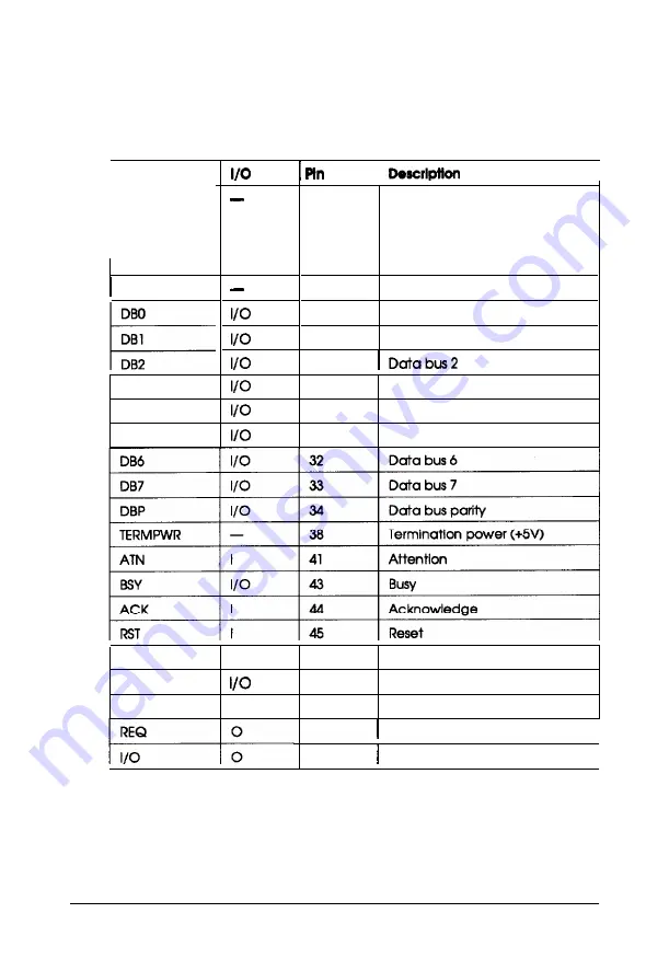
Signal pin assignments
In this table, the direction of the signals is given relative to the
scanner.
Signal
GND
I----
NC
No.
I
I
1-12
14-25
35-37
39-40
42
13
26
27
Ground
Not connected
Data bus 0
Data bus 1
28
DB3
29
Data bus 3
DB4
30
Data bus 4
DB5
31
Data bus 5
MSG
0
46
Message
SEL
47
Select
C/D
0
48
Control/Data
49
Request
I
50
Input/Output
I
4-10 Technical Specifications


