background image

Confidential

Technical manual

Thermal printer unit

EU-T432

English

4013753

Issued Date

            200         ,                    ,               

Issued by

Summary of Contents for EU-T432

Page 1: ...Confidential Technical manual Thermal printer unit EU T432 English 4013753 Issued Date 200 Issued by ...

Page 2: ...therwise without the prior written permission of Seiko Epson Your obligations under this Agreement are in addition to any other legal obligations Seiko Epson does not waive any right under this Agreement by failing to exercise it The laws of Japan apply to this Agreement Cautions Should any discrepancy exist between the contents of this document and the provisions of the Master Contract or Specifi...

Page 3: ...he maximum time power can be applied and the maximum voltage that can be applied to electronic components such as the head motor and magnets must be observed If the maximum time power can be applied or the maximum voltage that can be applied is exceeded the components mentioned above could overheat and start a fire or begin to smoke Always include protective circuitry governing the length of time ...

Page 4: ...tures and general specifications for the EU T432 Chapter 2 Operation Principle This chapter contains the outline and principles of mechanisms Chapter 3 Handling This chapter contains precautions on handling paper loading and unloading and removing jammed paper Chapter 4 Maintenance This chapter contains information on cleaning inspection lubrication and tools Chapter 5 Repair This chapter contains...

Page 5: ...rying Operation With a Loop 2 15 Paper Carrying Operation Without a Loop 2 17 Detector Mechanism 2 17 Control Circuit Board Module 2 18 DIP Switches 2 18 Memory Switches 2 20 Chapter 3 Handling Precautions 3 1 Transport Precautions 3 1 Carrying Precautions 3 1 Installation Precautions 3 2 Handling Precautions 3 2 Storage Precautions 3 4 Opening and Closing Modules Unit and Part 3 4 Paper Roll Supp...

Page 6: ...f the Printer Module 6 3 Pre assembly A Paper guide straight back unit 6 3 Pre assembly B Frame platen straight unit B 6 4 Pre assembly C Cutter motor assembly 6 7 Pre assembly D Cutter cover sub unit 6 8 Pre assembly E Cutter unit B 6 11 Pre assembly F Black mark detector sub assembly option 6 13 Main Assembly A Motor paper feed receipt B and Platen detector 6 14 Main Assembly B Paper guide strai...

Page 7: ...g sheet presenter module 6 44 Main Assembly A Printer module 6 49 Main Assembly B Cut sheet presenter module 6 52 Main Assembly C Roll paper supply module 6 53 Main Assembly D Control circuit board and Cover circuit boards upper lower 6 54 Main Assembly E Roll paper shaft assembly 6 57 Appendix EU T432 Exploded Diagram 1 Printer Module Exploded Diagram 2 Cut Sheet Presenter Module Exploded Diagram...

Page 8: ...sue Length of receipt 228 4 mm 9 maximum When the EU T432 is equipped with an optional loop guide 600 mm 23 6 Available for large paper roll core dimensions 203 mm 8 diameter maximum Supports ESC POS equivalent commands Able to print bar codes fence and ladder and graphics Options available for all models Japanese Kanji model Supports JIS Level 1 and 2 Simple Chinese model Supports GB50007 85 Trad...

Page 9: ... and Module Names The whole systems is called the EU T432 The EU T432 consists of four modules and the configuration of the modules are shown below Figure 1 1 EU T432 appearance paper roll supply module cut sheet presenter module control circuit board module printer module ...

Page 10: ...m 3 to 23 6 When the cut sheet is not looped 76 2 to 3000 mm 3 to 118 1 Print speed 150 mm s 5 9 s maximum Print width 72 mm 2 84 maximum recommended Reliability Receipt printing 300 000 times Printer Mechanism 15 000 000 lines Thermal head 100 km 62 14 miles 100 million pulses Paper roll Specified thermal paper Original paper No P350 KSP Original paper No TF50KS E NIPPON PAPER INDUSTRIES CO LTD O...

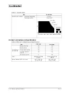
Page 11: ...nation of each module Paper roll module Yes Yes Printer module Yes Yes Control board module Yes Yes Cut sheet presenter module Yes Yes Paper supply spacer Yes Mass Approximately 3 8 kg 8 38 lb Approximately 3 9 kg 8 60 lb External dimensions W D H mm 194 7 170 6 300 7 7 6 7 11 8 194 7 170 6 350 7 7 6 7 13 8 Table 1 1 Specifications Item Specification 80 50 10 0 0 5 10 20 30 40 55 50 34 C 80 40 C 5...

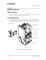
Page 12: ...The paper roll supply module holds a large diameter paper roll and guides the paper to the printer module This module consists of the paper holding part the paper load absorbing mechanism and the paper near end detector The appearance of this module is shown below Figure 2 1 Paper roll supply module appearance lever open paper NE detector shaft roll paper holder roll paper A holder roll paper shaf...

Page 13: ...r thickness you can replace it with an optional holder a holder roll paper B for the inner diameter of the paper core 50 8 mm 2 inch or a holder paper roll C for the inner diameter of the paper core 76 2 mm 3 inch Paper Load absorbing Mechanism The paper load absorbing mechanism consists of the guide roll paper tension that receives the paper tension Using the paper tensile force generated when fe...

Page 14: ...ppearance Drive Force Transmission Mechanism This mechanism consists of the motor paper feed receipt B fixed to pinion the gear reduction the gear idler and the gear platen The printer uses a stepping motor the rotation force of which is reduced in sequence by the gear reduction and the gear idler before being transmitted to the gear platen The arrows in the figure below indicate the direction of ...

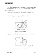
Page 15: ...sm consists of the platen paper feed roller and the thermal head When the motor paper feed receipt B rotates counterclockwise as viewed from the shaft the gear train transmits the motion to the platen which rotates in direction A Figure 2 4 Paper feed mechanism Paper feed operation during printing The platen presses the thermal paper against the thermal head with a constant force When the platen r...

Page 16: ...ck lever is located on the gear train side of the frame platen and locks the frame platen unit to the frame base The spring lock lever inside the lock lever pushes the lock lever back The pushplate platen B is secured on top of the frame platen and covers the fixed blade When the frame platen unit is closed the platen is in the print ready position where the gear platen and the gear idler are enga...

Page 17: ...thermal head and the thermal paper are shown below Printing is performed in the following steps Figure 2 7 Cross section of thermal head and thermal paper 1 Drive pulses are sent to the designated dot electrodes in accordance with the print signal 2 Since the resistor layers are formed at the top of each electrode inside of the thermal head the resistor layers are heated up when the drive pulses a...

Page 18: ...IFT REGISTER Using the LATCH LAT signal timing these data are then stored in the LATCH REGISTER Activated by the STROBE signals STR1 STR2 the stored print data is used to control the gate ON condition for the head heating element drive pulse This printer is equipped with two strobes and can print using a maximum of four divisions The drive pulse width is controlled by the control circuit board mod...

Page 19: ... mark detector mechanism Paper end detector mechanism The paper end detector mechanism is located inside the paper guide mechanism to detect the end of the thermal paper and the paper insertion state in the semi autoloading mode This mechanism consists of the transparent photo sensor the lever paper detector which presses against the thermal paper and the spring paper detector which pulls the leve...

Page 20: ...hoto sensor varies as shown in Figure 2 12 then the absence of paper is detected When the semi autoloading function is used the insertion of paper changes the status from no paper to paper Since the output level changes from LOW to HI the status changes to paper then the semi autoloading function is initiated Figure 2 11 Paper end detector mechanism Figure 2 12 Paper end detector operation platen ...

Page 21: ...detector circuit Head temperature detector mechanism The thermal head has a thermistor to detect the temperature of the thermal head Black mark detector mechanism The black mark mechanism is a device which can be attached inside the paper guide mechanism to determine the printing position when using pre printed thermal paper This mechanism uses the reflective photo sensor Figure 2 14 Black mark de...

Page 22: ...e mechanism the movable cutter blade mechanism and the emergency cutter mechanism The basic principle of the autocutter mechanism is an application of the scissors principle where the paper is cut by two crossing blades A configuration which allows the two blades to separate has been adopted so that the fixed blade separates from the movable cutter blade full when the platen is open Fixed blade me...

Page 23: ...vable cutter blade drive with the oval hole of the movable blade on the frame cutter Also the microswitch attached to the cover cutter is connected to the gear cutter drive enabling it to detect the position of the movable cutter blade The lead wires of the motor cutter and the microswitch are bound together and connect to the circuit board The shaft movable cutter blade is on the frame cutter sid...

Page 24: ...ontinues to rotate in the forward rotation The movable cutter blade full intersects with the fixed cutter blade and cuts the paper from the right to the left toward the first column 3 After cutting the paper the movable cutter blade full starts to return to the home position 4 As the movable cutter blade full approaches the home position the microswitch is switched from ON closed to OFF open then ...

Page 25: ...powered by the motor rotate the knob on the gear cutter worm with a tool such as a ball point pen or tweezers to move the movable cutter blade full to the home position The window on the cover cutter can be used to check if the movable cutter blade full has returned to the home position Figure 2 20 Home position check window Movable cutter blade in the home position knob ...

Page 26: ... the clockwise direction as seen from the shaft direction and the roller presenter rotates in the clockwise direction via the gears The roller cutting paper hold is pressed to the roller presenter by a spring The paper sent from the printer module is fed along the paper guiding part and fed between the roller presenter and the roller cutting paper hold When the tip of the paper reaches the detecti...

Page 27: ...eet is fed from the roller presenter to the paper exit When the paper eject sensor detects the end of the cut sheet the motor cutting paper feed stops With the cut sheet between the roller presenter and the roller cutting paper hold a series of operations is completed and the cut sheet is ejected from the paper exit A paper presence sensor can detect whether or not the cut paper is removed Figure ...

Page 28: ...tector Mechanism The detector mechanism consists of the presenter open sensor the paper eject sensor and the cut sheet presence sensor Presenter open sensor This sensor detects whether the cut sheet presenter module is open or not Paper eject sensor This sensor detects the paper presence in the paper feeding route Cut sheet presence sensor This sensor detects whether or not the cut sheet has been ...

Page 29: ...d module DIP Switches The circuit board has two DIP switches DSW 1 2 Each setting is as follows DIP Switch 1 Effective only when the serial interface is selected Table 2 1 DSW 1 SW No Function ON OFF Default Setting 1 Black mark detecotor Enabled Disabled OFF 2 Interface selection Refer to Table 2 2 3 4 Serial interface handshaking XON XOFF DTR DSR or CTS RTS OFF 5 Serial interface parity check Ye...

Page 30: ... 2 3 Baud Rate Selection Transmission speed bps Switch No 7 Switch No 8 4800 ON ON 9600 OFF ON 19200 ON OFF 38400 OFF OFF Table 2 4 DSW 2 SW No Function ON OFF Default setting 1 Model type selection Refer to Table 2 5 ON 2 OFF 3 Print density selection Refer to Table 2 6 4 5 Operation mode selection Refer to Table 2 7 6 Factory use OFF 1 7 I F pin 6 reset signal 1 Enabled Disabled OFF 2 8 I F pin ...

Page 31: ...with EPSON Advanced Windows Drivers The settings of the memory switches are as follows 1 Effective only in the serial interface model 2 Effective only in the parallel interface model Table 2 6 Print Density Selection Level Print Density Switch No 3 Switch No 4 1 Slightly light ON ON 2 Normal OFF OFF 3 Slightly dark ON OFF 4 Dark OFF ON Table 2 7 Operation Mode Selection Operation mode Switch No 5 ...

Page 32: ...r from the presenter 3 The print energy is applied according to the table below The values in the table below are relative ones assuming that the print energy for normal paper with normal density is 100 Table 2 10 Memory Switches 6 SW No Function ON OFF Default setting 1 to 2 Reserved Fixed to OFF OFF 0 3 Print speed control Speed has priority over power consumption Power consumption has priority ...

Page 33: ...n using with the cut sheet presenter module Table 2 11 Memory Switch 7 SW No Function ON 1 OFF 0 Default setting 1 Reserved Fixed to OFF OFF 0 2 and 3 Setting for the secondary paper near end position Refer to Table 2 12 OFF 0 1 4 Operation after cutting Ejects fully Clamps OFF 0 2 5 Paper initializing operation when the power is turned on Always cuts Detects paper s tip 6 to 8 Reserved Fixed to O...

Page 34: ...empty If this switch is turned on the printer clears the receive buffer when the offline status shown above occurs Then the printer executes any real time command DLE ENQ DLE EOT if it is there and discards all other data When the receive buffer is cleared if this switch is turned on three bytes of data 37H 24H and 00H are transmitted can be either setting Table 2 13 Memory Switch 8 SW No Function...

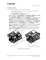
Page 35: ... a green sticker on it on the paper roll supply module when carrying the printer as shown below When this product is equipped with an optional loop guide you can hold the loop guide to carry it Note Do not hold parts other than those mentioned above otherwise you can cause damage or deformation of parts that will affect the operation of the printer When you put this unit on a place such as a desk ...

Page 36: ...n be hot during and right after printing never touch them with your bare hands allow about 15 minutes for them to cool Since the EU T432 contains permanent magnets in the motor as well as electromagnets they should not be used in an environment with excessive dirt dust or metallic dust Never print without paper installed or with the head away from the platen because the life of the thermal head ma...

Page 37: ... Do not apply excessive pressure when operating the cut sheet presenter module Do not turn off the power during operations because that could cause a paper jam Control circuit board module The serial interface is secured with inch type hexagonal lock screws If you need to use millimeter type screws replace the inch type screws with the millimeter type screws enclosed in the box Paper roll Use only...

Page 38: ...art Follow the steps below to open and close modules unit and part you want See Figure 3 2 on page 3 5 Note Do not apply excessive pressure to any operational part otherwise its function may be damaged because of deformation or damage of the part Apply pressure to each operational part only in the specified direction otherwise its function may be damaged because of damage or deformation of the par...

Page 39: ...he original position At this time make sure that the mounting dowels on both sides are securely engaged with the mounting parts on the cut sheet presenter module Paper guide upper To open the paper guide upper lift up the knob on the right edge of the paper guide Figure 3 2 Opening closing units and module plate opening and shutting paper guide upper paper roll supply module lever platen cut sheet...

Page 40: ... roll paper which meets the inside diameter of the paper core to the shaft roll paper then secure it with a C ring Note At the default setting the holder roll paper A for the 25 4 mm 1 inner diameter paper core is attached to the paper roll supply module Since other holders are available as optional parts use the holder roll paper that meets your paper core size The holder roll paper B is for a 50...

Page 41: ...riginal position until it is locked by the frame open lever with a click sound Then turn it back so that the plate paper guide is not deformed Figure 3 3 Loading and removing the paper roll holder roll paper shaft roll paper roll paper holeder paper roll supply module C ring panel switches plate paper guide ...

Page 42: ...ed by the paper end detector of the printer module it is fed automatically in the semi autoloading mode 5 When the semi autoloading is finished the extra paper is cut automatically 6 Remove the extra paper from the paper exit Note Performing operations other than above can cause improper paper feeding and jamming Make sure that the paper is not wrinkled or torn To avoid paper jams do not fold the ...

Page 43: ...t the paper from the paper slot of the printer module 3 Open the paper roll supply module 4 Pull the paper upward and remove it from the paper roll supply module 5 Remove the paper core from the holder paper roll Removing Jammed Paper Follow the steps below to remove jammed paper from each module See Opening and Closing Modules and Other Parts on page 3 4 when opening modules if necessary CAUTION ...

Page 44: ...r so that the paper NE detector can be moved in the direction of arrow in the illustration on next page 3 Tighten the paper NE detector with the screw NE detector at the position you want for the paper NE detector The hole numbers for the paper NE detector fixing hole and the paper roll diameters detected by the paper NE detector are as follows Note Because the amount remaining on the paper roll w...

Page 45: ...U T432 Technical Manual Confidential Figure 3 5 Setting of the paper NE detector paper NE detector back side screw paper NE detector 1 2 3 4 5 6 7 8 9 hole No paper roll supply module for 6 inch type for 8 inch type 1 to 8 ...

Page 46: ...e If you want to continue SELF TEST printing please press FEED button is printed then the PAPER OUT LED starts to flash 4 Press the paper feed button again while the PAPER OUT LED is flashing then the printing for the test pattern printing is resumed Self Test End After a number of lines are printed the message completed is sprinted at the end of the self test then the unit enters the normal opera...

Page 47: ...rror The LED indicates the following Automatic recovery error Note The high temperature error of the print head is not an abnormality When the head cools down to 70 C or less the unit recovers automatically Table 4 4 POWER LED Error Error type LED flashing pattern Cause Power supply error Not lit The power supply connector is unplugged The fuse F1 is blown out Table 4 5 PAPER LED Error Error type ...

Page 48: ...ack mark is fed Presenter error A paper jam has been detected in the cut sheet presenter module Table 4 8 Recovery impossible error Error type LED flashing pattern Cause CPU execution error The CPU has executed an incorrect address R W error in memory or G A After R W checking the printer does not work correctly High voltage error The power supply voltage is extremely high Low voltage error The po...

Page 49: ...ollect dust after printing for a long period of time because of heat sensitive materials contained in the paper that could affect printing quality Therefore cleaning the thermal head using the steps below is rocommended See Opening and Closing Modules and Other Parts on page 3 4 for opening the module and the platen unit if necessary 1 Turn off the power 2 Open the cut sheet presenter module 3 Ope...

Page 50: ...ubrication point and lubricate when necessary Note When opening the units and cleaning them be sure not to damage parts and paper detectors disconnect wires or unplug connectors Removing Foreign Matter When the Cutter Locks Follow the procedures below to remove foreign matter when the cutter of the printer module locks After rotating the motor in reverse so that the movable cutter blade full retur...

Page 51: ...unit the cut sheet presenter module the cover circuit board are open Close the units or the modules Paper chips or foreign matter inside the product No paper chips or foreign matter is inside the product Remove paper chips or foreign matter Paper state Specified paper is used Replace with the specified paper No discolored or torn paper is used Replace with a new paper roll Table 4 2 Periodic Check...

Page 52: ...the end of this manual for the lubricants and the lubrication points Lubrication Point The lubrication points are as follows Note The lubrication point numbers in the table are the same as those in the lubrication diagrams at the end of this manual Table 4 2 Lubrication Point Module Number Lubrication point Lubrication type Amount of lubricant Printer module 1 Two points where the screw on the loc...

Page 53: ...G 36 40 gr Table 4 4 Tool List Tool name Commercial availability Brush 1 Yes Cleaning brush Yes Crosshead screwdriver 0 1 and 2 Yes ET holder No 1 5 2 2 5 3 3 5 and 4 Yes Tweezers Yes Diagonal cutting nippers Yes Pliers Yes Electric solder iron Yes Wrist band Yes Table 4 5 Measuring Equipment List Name Standard Multimeter DC voltage 400 V max Resistance measurable Oscilloscope 500 MHz with storage...

Page 54: ... B Requires a certain degree of knowledge of the printer s operating principles and structure as well as skills and experience using special tools for disassembly and assembly of the printer Phenomenon Find the type of problem in this column Condition Check the condition of malfunction by referring to this column Cause Locate the cause of the problem by referring to this column Also the repair lev...

Page 55: ... Paper detector failure 1 Paper chips or foreign matter is jammed around the paper detector A Check whether paper chips or foreign matter is jammed around the paper detector Remove the paper chips or foreign matter if there is any 2 Paper chips or foreign matter is jammed around the paper NE detector A Check whether paper chips or foreign matter is jammed around the paper NE detector Remove the pa...

Page 56: ...foreign matter is inside the autocutter and has locked it B Check whether paper chips or foreign matter is jammed inside the autocutter After turning off the power remove paper chips or foreign matter then turn on the power 2 The internal function of the autocutter is damaged B Check the power supply voltage Replace the autocutter if the power supply voltage is normal Black mark detection error 1 ...

Page 57: ...e missing continuously 1 Foreign matter is attached to the head heating elements A See if anything is wrong with the head heating elements Clean the head heating elements if foreign matter attached 2 The head heating elements are damaged A Replace the thermal 3 Head failure Dr IC etc B Check with an oscillo scope if the input pulse is within the specified range If the input pulse is normal replace...

Page 58: ...ee or check with a magnifier the platen surface Replace the platen if the platen surface is damaged or deformed Abnormal or incorrect printing Abnormal or incorrect printing 1 Thermal head input pulse failure B Check with an oscillo scope if the input pulse is within the specified range If the input pulse is abnormal replace the control circuit board 2 Thermal head failure Dr IC etc B If input pul...

Page 59: ...nected A Check if each paper feed motor is connected properly Connect the connector properly 3 Power transmission parts gears are damaged or foreign matter is caught between gears B Check the power transmission state of each gears Check if no foreign matter is caught between geas Replace damaged gears Remove foreign matter if there is any Paper feeding pitch is defective The character spacing is n...

Page 60: ... inside the autocutter A Check whether foreign matter is inside the autocutter Remove foreign matter if there is any 2 Abnormal input signal or inner mechanism damage of the autocutter B Check the power supply voltage input signal and operation of the cutter motor Replace the control circuit board module if there is any problem with the power supply voltage input signal Replace the motor if there ...

Page 61: ...2 6 F Zn C B P tite M3 8 Cross resessed binding head P tite self tapping screw 3 8 F Zn C B S tite M2 5 4 Cross recessed binding head S tite self tapping screw 2 5 4 F Zn C B S tite M3 5 Cross recessed binding head S tite self tapping screw 3 5 F Zn C B S tite M3 12 Cross recessed binding head S tite self tapping screw 3 12 F Zn C C P tite M2 5 6 Cross resessed cup head P tite self tapping screw 2...

Page 62: ...ate places where checks are required Make sure to follow the instructions given in these places Circled numbers in the Reassembly step indicate that lubrication is required during the reassembly of that component and that such lubrication will be difficult unless performed during reassembly Refer to Lubrication in Chapter 4 for lubrication details on the printer module and other modules Also see t...

Page 63: ...traight back unit Reassembly step Part name Assembly procedure 1 Paper detector assembly 2 Paper guide straight back Slide the paper detector assembly onto the paper guide straight back Check Make sure that the paper detector assembly is installed securely as shown below paper detector assembly paper guide straight back Install securely ...

Page 64: ... the cover fixed blade and the fixed blade on the frame platen then secure them with shouldecs 5 Spring fixed blade Shouldec 2 6 2 2 At this time install the spring fixed blade on one of the shouldecs as shown below Check Tightening torque 177 to 226 mN m 1 8 to 2 3 kg cm Make sure to install the fixed blade right side up Make sure that the dowels on the frame platen fit securely into the holes on...

Page 65: ...ame platen and secure it with a screw Check Tightening torque 490 to 539 mN m 5 0 to 5 5 kg cm 7 Spring lock lever Hook the ends of the spring lock lever onto the lock lever assembly and C B B tite M2 6 from the inside of the frame platen Check Make sure that the spring lock lever is hooked securely push plate platen B frame platen C C P tite M2 5 6 C B B tite M2 6 spring lock lever lock lever ass...

Page 66: ...ing platen R E 2 5 1 After Installing the platen straight assembly to the frame platen install the bearing platen from the outside of the frame platen then secure it with an R E Lubricate with G 15 two points where the screw on the lock lever assembly is secured platen straight assembly bearing platen R E 2 5 bearing platen frame platen G 15 ...

Page 67: ... the lead wire paper cutter to the microswitch 3 Cutter motor sub assembly Solder the red wire of the lead wire paper cutter to the red marked terminal side of the cutter motor sub assembly and solder the black lead wire to the other terminal Check Make sure to arrange the lead wires properly microswitch white lead wire paper cutter black red No polarity red mark red black lead wire paper cutter c...

Page 68: ...t on the cutter cover sub assembly Gear reduction A C 4 Washer clutch 5 Spring cutter clutch After lubricating the bore of the gear reduction A C with G 36 attach the washer clutch and the spring cutter clutch to the gear reduction A C then install it to the cutter cover sub assembly Check Make sure not to damage the clutch teeth when installing the gear reduction A C gear cutter worm G 36 cutter ...

Page 69: ...cure it with the C B M2 2 5 Install the microswitch to the cutter cover sub assembly and secure it with the screw switch Check Tightening torque 245 to 294 mN m 2 5 to 3 0 kg cm C B M2 2 5 Tightening torque 108 to 147 mN m 1 1 to 1 5 kg cm screw switch Make sure to install the cutter motor with the labeled side down Make sure that the cutter motor is installed securely Make sure that the dowel on ...

Page 70: ...utter drive gear sub assembly and the plain washer on the shaft then secure them with an R E Check Make sure not to apply excessive pressure to the microswitch actuator when installing the cutter drive gear sub assembly Make sure not to damage the cutter drive gear sub assembly when securing it with the R E Lubricate the specified areas with G 36 R E 2 5 plain washer cutter drive gear sub assembly...

Page 71: ...ame assembly together insert the shaft movable cutter blade drive into the oval hole on the movable cutter blade Check Tightening torque 834 to 932 mN m 8 5 to 9 5 kg cm Make sure that the shaft movable cutter blade drive fits securely into the oval hole on the movable cutter blade Make sure that the edges of the cutter cover sub unit fit into the hooks on the cutter frame assembly C B S tite M3 5...

Page 72: ...m 1 0 to 1 5 kg cm Make sure that the dowels on the cutter cover sub unit is fitted in the holes on the emergency cutter full B 4 Plate A C assembly Peel the backing off of a couple face tape Hook the bent part of the plate A C to the edge of the cover cutter Align parts A and B with the holes on the plate A C as shown below and stick the plate to the cutter cover sub unit C B M2 2 5 mounting posi...

Page 73: ...ew M2 3 1 Install the B M detector sub assembly in one of the two detector mounting holes on the paper guide and secure it with a screw Both the straight path and the curved path types can be installed this way Check Tightening torque 167 to 186 mN m 1 7 to 1 9 kg cm Make sure that the detector fits securely into the detector mounting hole on the paper guide C P tite F screw M2 3 B M detector sub ...

Page 74: ... B with the mounting position on the frame assembly and secure it with scerws Check Tightening torque 834 to 932 mN m 8 5 to 9 5 kg cm Make sure that the motor paper feed receipt B is oriented properly 3 Platen detector assembly C P 1 6 5 1 Align the platen detector assembly to the mounting position on the frame assembly and secure it with a screw motor paper feed receipt B C B S tite 3 5 frame as...

Page 75: ... EU T432 Technical Manual Confidential Main Assembly A Reassembly step Part name Assembly procedure Check Tightening torque 147 to 196 mN m 1 5 to 2 0 kg cm After installing the platen detector assembly arrange the lead wires lead wires ...

Page 76: ...n guide straight into the holes on the paper guide straight front 3 Paper guide straight back unit C B 2 5 4 4 4 4 2 After putting the paper guide straight front and the paper guide straight back unit together install them to the mounting holes on the frame assembly and secure them with screws paper guide straight front pin guide straight C B M2 5 4 frame assembly paper guide straight back unit mo...

Page 77: ...he dowels on the paper guide straight back unit fit securely into the holes on the frame assembly Make sure that the lead wires of the paper detector assembly are not caught between the frame assembly and the paper guide straight back unit Make sure that the wires of the paper detector assembly are passed under the hook on the paper guide straight back unit hook paper guide straight back unit ...

Page 78: ...e platen straight unit B to the frame assembly 4 Shaft frame platen R E 1 5 1 Align the holes on the frame assembly and the frame platen straight unit and insert the shaft frame platen into these holes then secure it with an R E 5 6 Lever platen Spring lever Install the spring lever on the lever platen as shown below frame platen straight unit B dowel frame assembly G 36 point where the frame asse...

Page 79: ...he spring lever 7 R E 2 1 Install the lever platen to the shaft frame platen and secure it with an R E Check Make sure that the shaft lock lever is placed properly into the specified position on the lever platen 8 Remove the longer edge of the spring lever and hook it on the shaft lock lever groove longer edge shaft frame platen lever platen R E 2 shaft lock lever shaft lock lever lever platen lon...

Page 80: ...e frame assembly Check When handling the thermal print head assembly use proper body grounding procedures to avoid static electricity Use a conductive mat and wrist band during assembly Do not touch the connector terminals and the surface of the thermal print head assembly If foreign matter attaches to them wipe off the foreign matter lightly using a cotton swab dampened with alcohol thermal print...

Page 81: ...head 2 Install the spring press head to the plate pressure spring Check Make sure that the spring press head is pushed securely into the plate pressure spring 4 Hook the edge of the spring press head to the groove of the thermal print head assembly while pushing the plate pressure spring in the arrow direction then hook it to the groove of the frame assembly plate pressure spring C B S tite M2 5 4...

Page 82: ...ake sure that the lead wires of the paper detector assembly and the paper detector assembly are passed under the plate pressure spring Make sure that the edge of the spring press head fits securely into the groove on the thermal print head assembly Make sure that the plate pressure spring is hooked securely into the hole on the frame assembly lead wires plate pressure spring spring press head ther...

Page 83: ...ing plate to the bearing platen Check Tightening torque 834 to 932 mN m 8 5 to 9 5 kg cm Make sure that the edge of the fixing plate is pushed securely to the bearing platen 2 Gear reduction 3 Gear idler R E 2 5 2 Install the gear reduction and the gear idler to the shafts on the frame assembly and secure them with R E s Check Make sure not to deform the shaft on the frame assembly when securing w...

Page 84: ...k Tightening torque 834 to 932 mN m 8 5 to 9 5 kg cm Make sure that the lead wire paper cutter is passed through the hook on the frame assembly properly as shown above Make sure that the lead wire paper cutter is not caught between any places when securing the cutter unit Install the cutter unit B in the platen up state Lubricate the point where the fixed blade of the cutter unit B contacts the cu...

Page 85: ...ted securely 2 All lead wires should be passed through the hook on the frame assembly and arranged inside of the printer Check Make sure that any of the lead wires are not caught by the projections the colored part Make sure not to damage the coats of the lead wires when arranging the lead wires variable resistor connector for the platen detector assembly connector for the motor paper feed receipt...

Page 86: ...head is oriented properly when connecting Make sure that the cable head is inserted securely 2 Cable printer Insert the cable printer in the connector on the circuit board assembly Check Make sure that the cable printer is oriented properly when connecting Make sure that the cable printer is inserted securely 3 Pull out the cable head and the cable printer as shown below connector for the cable pr...

Page 87: ... the gray side of the card is inserted along the paper guide which the B M detector sub assembly is installed 4 Adjust the output power voltage of the B M detector at 1 74 V using the variable resistor on the circuit board assembly Turn the slot on the variable resistor to the right and the left with a tool such as a flat head driver to adjust the output power voltage If the reflectance of black m...

Page 88: ...able printer through the hole on the cover cable 3 Attach the cover cable to the mounting position on the cutter unit B and tighten C B S tite M3 5 again to secure the cover cable Check Tightening torque 834 to 932 mN m 8 5 to 9 5 kg cm Make sure that the cover cable is attached securely frame main Make sure that none of the lead wires are caught by any part C B S tite M3 5 cover cable cable print...

Page 89: ...te M3 5 that secures the motor paper feed receipt B 2 Cover gear Hook the cover gear to the frame main and the shaft frame platen while aligning with the mounting positions and secure it Check Tightening torque 834 to 932 mN m 8 5 to 9 5 kg cm The hooking parts on the cover gear are hooked securely to the frame main C B S tite M3 5 cover gear shaft frame platen cover gear ...

Page 90: ...ly 1 C B S tite M3 5 2 Secure the frame paper supply assembly with C B S tite M3 5 Check Tightening torque 735 to 931 mN m 7 5 to 9 5 kg cm 2 Damper 1 Stick the damper on the frame paper supply assembly Check Damper position to stick Right and left sides The center from both sides Upper and lower sides Align with the sticking surface on the plate damper C B S tite M3 5 frame paper supply assembly ...

Page 91: ... 3 0 8 8 to the screw 5 Plate rotation stopper 1 H nut 4 1 Attach the plate rotation stopper to the P washer attached in step 4 so that the bent part of the plate rotation stopper is fit into the square hole on the frame paper supply assembly then secure it with an H nut 9 C B M4 16 1 P washer 4 3 0 8 8 3 Collar screw holder 1 Gear frame open assembly 1 Conical S washer 1L 4 4 Plate rotation stopp...

Page 92: ...under the power circuit board 12 Insert the switch connector into the power supply connector 13 Plate paper guide L 1 Plate paper guide R 1 C B S tite M3 5 2 Attach the plate paper guide L R to the frame paper supply assembly and secure them with C B S tite M3 5 screws Check Installation position of the plate paper guide L R The outer sides of the plate paper guide L R s oval holes are aligned wit...

Page 93: ...ires for the power supply connector through the square hole on the frame paper supply and secure them with wire bands at two places Check The lead wires for the upper fastening position should be arranged behind the bent part of the frame Reassembly step Part name Assembly procedure square hole wire bands SKB 85 ...

Page 94: ... cm 3 Gear frame opening and shutting 1 P washer 3 0 5 7 1 H nut 3 1 C F 3 8 1 Align the gear frame opening and shutting with the dowels on the frame roll paper holder from inside and attach a C F 3 8 screw to it from the outside Secure the gear frame opening and shutting with an H nut 3 via a P washer 3 2 0 5 7 Check Tightening torque 539 to 637 mN m 5 5 to 6 5 kg cm 4 Gear frame opening and shut...

Page 95: ...tor assembly to the frame roll paper holder with a C B S tite M3 5 screw Check Tightening torque 735 to 931mN m 7 5 to 9 5 kg cm NE detector mounting position 6 inch type lower and 8 inch type upper 8 C B S tite M3 5 1 Align the center of the NE detector s dowel at A on the scale gradation then secure the NE detector with a C B S tite M3 5 screw A Default setting Check Tightening torque 735 to 931...

Page 96: ...er holder R assembly with the square holes A from the inside of the frame roll paper holder then secure the assembly with C B M3 x 8 screws from the outside The dowels and square holes B for the roll paper holder R assembly B Check Tightening torque 539 to 637 mN m 5 5 to 6 5 kg cm Reassembly step Part name Assembly procedure roll paper holder R assembly for 6 inch type spring roll paper holder sp...

Page 97: ...th the square holes and the notch C on the frame and the cover NE detector from the inside of the frame roll paper holder then secure the assembly with C B M3 8 screws from the outside The dowels holes and notch D for the roll paper holder L assembly B Check Tightening torque 539 to 637 mN m 5 5 to 6 5 kg cm Reassembly step Part name Assembly procedure C B M3 8 mounting position for 8 inch type sq...

Page 98: ...to the frame with the wire band SKB 85 at three points 14 Take out the connector of the lead wire NE detector trough the round hole on the frame Check The fastening part should be under the cover Reassembly step Part name Assembly procedure wire band SKB 85 round hole lead wire NE detector fastening part ...

Page 99: ...ollar screw holder on the frame from outside so that the bent part on the plate rotation stopper assembly is fit in the square hole on the frame 4 P washer 4 3 0 8 8 1 H nut 4 1 Attach a P washer 4 3 x 0 8 x 8 from inside of the frame then secure it with an H nut 4 Check Tightening torque 441 to 539 mN m 4 5 to 5 5 kg cm 5 Collar screw holder 1 C B M4 16 1 S washer 2 4 1 Plate rotation stopper ass...

Page 100: ...ly 1 with a large lever into the snap fastener on the the circuit board side Check Make sure that the paper detector assembly 1 is fit securely into the snap fasteners 3 Paper detector assembly 1 Slide the paper detector assembly with a small lever to the other snap fastener Check Make sure that the paper detector assembly is fit securely into the snap fasteners Make sure the correct mounting posi...

Page 101: ... middle 1 Frame presenter right 1 C B S tite M3 5 1 C B S tite M3 12 1 Secure the frame presenter middle and the frame presenter right with a C B S tite M3 5 screw and a C B S tite M3 12 screw Check Tightening torque 735 to 931 mN m 7 5 to 9 5 kg cm Make sure that each screw is used for the right position frame presenter middle C B S tite M3 12 C B S tite M3 5 frame presenter right ...

Page 102: ...sembly step Part name Assembly procedure 1 Frame presenter left 1 Presenter motor assembly 1 C P M2 2 2 Secure the presenter motor assembly to the frame presenter left with C P M2 2 screws Check Tightening torque 294 to 392 mN m 3 0 to 4 0 kg cm C P M2 2 frame presenter left presenter motor assembly ...

Page 103: ...o the paper guide sub assembly 2 Shaft cutting paper hold roller 1 R E 3 6 Pass the shaft cutting paper hold roller through the roller cutting sheet hold and secure it with R Es Check Make sure not to deform the plate paper guide L R of the paper guide sub assembly roller cutting sheet hold paper guide sub assembly roller cutting sheet hold R E 3 R E 3 paper guide sub assembly shaft cutting paper ...

Page 104: ...y attach it to the presenter frame left assembly Attach the presenter frame left assembly to the frame presenter middle from inside and secure it with C B S tite M3 5 screws Check Tightening torque 735 to 931 mN m 7 5 to 9 5 kg cm Lubricate the motor gear on the printer motor assembly with G 36 3 Spring paper guide hold 1 Attach the spring paper guide hold to the screw which secures the presenter ...

Page 105: ... the frame presenter middle then secure it with C B P tite M3 8 screws Check Tightening torque 735 to 931 mN m 7 5 to 9 5 kg cm Reassembly step Part name Assembly procedure C B P tite M3 8 projection on the presenter table assembly presenter table assembly C B P tite M3 8 frame presenter middle projection on the presenter table assembly concave part on the presenter frame right assembly concave pa...

Page 106: ...senter frame left assembly side using the same steps Hook the spring cutting paper hold shaft B to the projection on the presenter frame right assembly and the shaft of the paper guide assembly Secure the spring cutting paper hold shaft B and the spring cutting paper hold shaft on the presenter frame left with R Es 6 Unhook the leg of spring which has hooked on the presenter frame middle in step 2...

Page 107: ...er guide to the presenter frame middle with C B S tite M3 5 screws Check Tightening torque 735 to 931 mN m 7 5 to 9 5 kg cm 9 paper exit guide assembly 1 Plapoint 3 6 1 Attach the paper exit guide assembly sliding so that protrusions fit into the five notches on the frame presenter middle assembly then secure it with the plapoint Check Tightening torque 73 5 to 98 0 mN m 0 75 to 1 0 kg cm Reassemb...

Page 108: ...e lead wire presenter with wire bands at two places wire bands Connect the paper detector assembly 1 the paper detector assembly and the motor presenter to the connectors on the circuit board assembly Fasten lead wires with wire bands wire bands and Check Paper detector assembly 1 Connect to the blue connector Reassembly step Part name Assembly procedure C P 2 6 PO detector connector for the lead ...

Page 109: ... 3 Plate roll paper tension 1 Guide roll paper tension 2 C B M3 4 2 Attach the plate roll paper tension to the guide roll paper tension so that the plate will be inside of the guide aligning the holes on the plate with those on the guide then secure it to the fixing plate printer assembly with C B M3 4 screws Check Secure the guide roll paper tension so that it is placed in the center of the paper...

Page 110: ... 5 2 Secure the plate opening and shutting assembly to the fixing plate printer assembly with C B S tite M3 5 screws Check Tightening torque 735 to 931 mN m 7 5 to 9 5 kg cm Do not attach the plate opening and shutting assembly when an optional 600 mm loop guide is equipped Reassembly step Part name Assembly procedure cable printer insulating tape C B S tite M3 5 plate opening and shutting assembl...

Page 111: ...ixing plate printer assembly with C B S tite M3 5 screws Check Tightening torque 735 to 931 mN m 7 5 to 9 5 kg cm 6 Plate loop guide 1 C B S tite M3 5 2 Secure the plate loop guide to the fixing plate printer assembly with C B S tite M3 5 screws Check Tightening torque 735 to 931 mN m 7 5 to 9 5 kg cm Reassembly step Part name Assembly procedure C B S tite M3 5 plate loop guide C B S tite M3 5 hol...

Page 112: ...n the both side then secure them with C B S tite 3 12 screws 4 Hook the spring presenters to the hooks on the both side of the cut sheet presenter frame Check Tightening torque 735 to 931 mN m 7 5 to 9 5 kg cm 5 Wire band SKB 85 1 Fasten the lead wires of the lead wire presenter to the fixing plate printer assembly with a wire band Check Fasten the lead wires with the cut sheet presenter module op...

Page 113: ...ply module 1 Spacer paper supply 2 C B S tite 3 5 4 Attach the spacer paper supply to the roll paper supply module and secure it with C B S tite 3 5 screws Check Tightening torque 735 to 931 mN m 7 5 to 9 5 kg cm 2 C B S tite 3 5 4 Attach the fixing plate printer assembly to the spacer paper supply and secure it with C B S tite 3 5 screws Check Tightening torque 735 to 931 mN m 7 5 to 9 5 kg cm C ...

Page 114: ...r the NE detector assembly through the round hole on the cover circuit board lower At this time the lead wire presenter from the square hole on the presenter frame right assembly should be under the cover circuit board lower 3 C B 3 4 3 Attach the cover circuit board lower to the fixing plate printer and secure it with C B 3 4 screws Check Tightening torque 539 to 637 mN m 5 5 to 6 5 kg cm How to ...

Page 115: ... circuit board lower with C B 3 4 screws Check Tightening torque 735 to 931 mN m 7 5 to 9 5 kg cm When securing the control circuit board module slightly push it downward Pass the hooks of the parallel interface through the hole on the circuit board lower 5 LED switch circuit board assembly 1 C B M3 4 2 Secure the LED switch circuit board assembly with C B M3 4 screws Check Tightening torque 735 t...

Page 116: ...per and secure it with plapoints Check Tightening torque 73 5 to 98 mN m 0 75 to 1 0 kg cm Two hooks on the cover circuit board upper are fit into the square holes on the cover circuit board lower The lead wires should not be caught 9 Dust cap 1 COM cover 1 Attach the dust cap and the COM cover to the serial and parallel connectors on the control circuit board module Reassembly step Part name Asse...

Page 117: ...aft assembly Reassembly step Part name Assembly procedure 1 Roll paper shaft assembly A 1 Roll paper shaft assembly B Roll paper shaft assembly C Attach the roll paper shaft assembly to the roll paper holder L R assembly roll paper shaft assembly roll paper holder L assembly roll paper holder L assembly ...

Page 118: ... upper C B S tite M3 4 C B S tite M3 4 LED switch circuit board assembly lead wire NE detector lead wire presenter dust cap COM cover control circuit board module cover circuit board lower H nut 2 6 plate roll paper tension guide roll paper tension plate opening and shutting assembly fixing plate printer assembly spacer paper supply shaft presenter fulcrum spring presenter C B S tite M3 12 roll pa...

Page 119: ... paper guide straight front C B M2 5 4 C P tite F screw M2 3 C B S tite M2 5 4 circuit board assembly spring press head paper detector assembly platen detector assembly C P M1 6 5 frame assembly motor paper feed receipt B plate pressure spring cutter frame assembly C B S tite M3 5 R E 2 5 washer 3 0 5 7 cutter drive gear sub assembly C B M2 2 5 screw switch microswitch C B M2 3 3 lead wire paper c...

Page 120: ... platen shaft holder presenter roller assembly R E 3 platen shaft holder presenter motor assembly spring paper guide hold table presenter paper detector assembly 1 paper detector assembly circuit board assembly lead wire presenter plain washer 4 0 8 10 C B P tite M3 8 spring cutting paper hold shaft B spring cutting paper hold shaft R E 3 C B S tite M3 12 frame presenter right roller cut sheet pap...

Page 121: ...8 8 H nut 4 Mounting holes for 8 inch type of roll paper holder L assembly C B M3 4 power supply connector assembly collar screw holder plain washer 4 3 0 8 8 C B M4 16 C B S tite M3 5 plate paper guide R gear frame open assembly plain washer 4 3 0 8 8 conical S washer 1L 4 H nut 4 plate rotation stopper conical S washer 1L 4 plain washer 4 3 0 8 8 gear frame open assembly damper C B S tite M3 5 c...

Page 122: ...Rev A Appendix 5 EU T432 Technical Manual Confidential EU T432 Lubrication Diagram 13 G 36 13 G 36 ...

Page 123: ...x 6 EU T432 Technical Manual Confidential Printer Module Lubrication Diagram 7 G 36 1 G 15 4 G 36 6 G 36 8 G 15 8 G 15 9 G 15 9 G 15 10 G 15 11 G 36 12 G 15 10 G 15 7 G 36 4 G 36 3 G 36 6 G 36 6 G 36 2 G 36 4 6 3 6 ...

Page 124: ...Rev A Appendix 7 EU T432 Technical Manual Confidential Cut Sheet Presenter Module Lubrication Diagram 14 G 36 ...

Page 125: ...Rev A Appendix 8 EU T432 Technical Manual Confidential Roll Paper Supply Module Adhesive Diagram Note Screw Lock Green is used for all adhesive parts of the cut sheet presenter module ...

Page 126: ...SEIKO EPSON CORPORATION Printed in Japan ...

Reviews: