


6-54
Assembly and Disassembly
Rev. A
Confidential
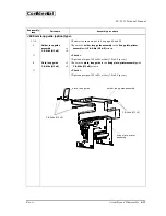
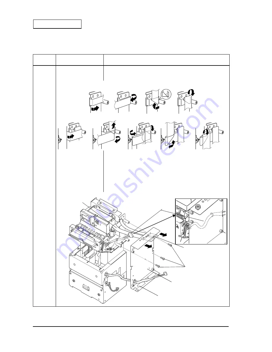
Main Assembly D: Control circuit board and Cover, circuit boards upper/ lower
Reassembly
step
Part name
Assembly procedure
1
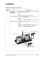
Cover, circuit board lower
❏
Fold the
cable, printer
and the
cable head
of the printer module (see
below), and pass them through the square hole on the
cover, circuit
board lower
.
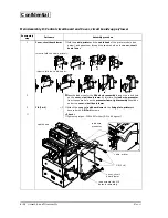
2
❏
❏
❏
❏
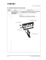
Pass the lead wires for the
NE detector assembly
through the round hole
on the
cover, circuit board lower
. At this time, the
lead wire, presenter
from the square hole on the
presenter frame, right assembly
should be
under the
cover, circuit board lower
.
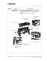
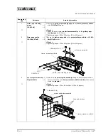
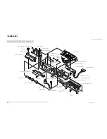
3
C.B (3
××××
4)
×
3
❏
Attach the
cover, circuit board lower
to the
fixing plate, printer
and
secure it with
C.B (3
××××
4)
screws.
★
< Check >
❏
Tightening torque: 539 to 637 mN
•
m {5.5 to 6.5 kg
•
cm}
<How to fold the cable, printer>
<How to fold the cable head>
cable, printer
cable head
cover, circuit
board lower
lead wires for the NE
detector assembly
C.B (3
×
4)
lead wire,
presenter


