


6-56
Assembly and Disassembly
Rev. A
Confidential
7
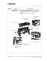
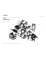
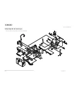
❏
Connect the
NE detector assembly
, the
cut sheet presenter module
, the
power supply connector assembly
, and the
LED switch circuit board
assembly
to the connectors on the
control circuit board module.
At this
time, pass the
lead wire, presenter
on the notch on the
cover, circuit
board lower
.
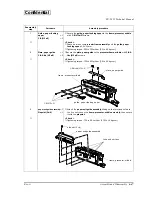
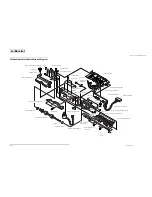
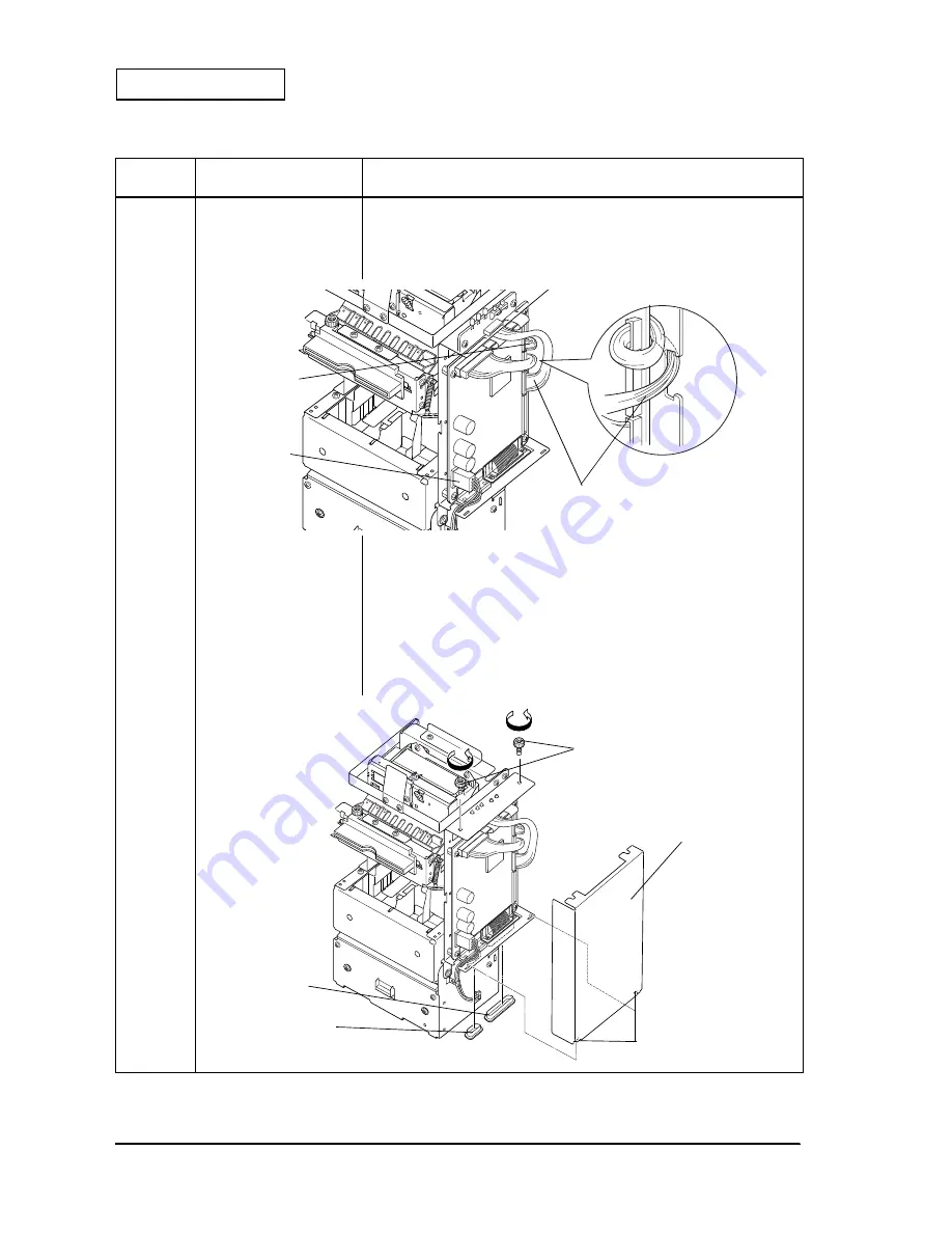
8
Cover, circuit board upper
×
1
Plapoint, 3
××××
6
×
2
❏
Attach the
cover, circuit board upper
and secure it with
plapoint
s.
★
< Check >
❏
Tightening torque: 73.5 to 98 mN
•
m {0.75 to 1.0 kg
•
cm}
❏
Two hooks on the
cover, circuit board upper
are fit into the square holes
on the
cover, circuit board lower
.
❏
The lead wires should not be caught.
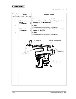
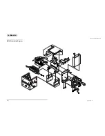
9
Dust cap
×
1
COM, cover
×
1
❏
Attach the
dust cap
and the
COM, cover
to the serial and parallel
connectors on the
control circuit board module
.
Reassembly
step
Part name
Assembly procedure
connector for the LED switch
circuit board assembly
connector for
the power
supply
connector
assembly
connector for
the NE detector
assembly
plapoint
cover, circuit board
upper
hook
COM, cover
Dust cap


