


Rev. A
Assembly and Disassembly 6-27
EU-T432 Technical Manual
Confidential
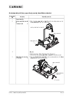
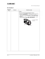
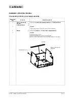
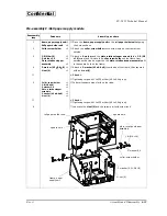
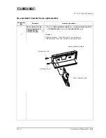
Assembly J: Black mark detector Adjustment
Adjustment
step
Adjustment procedure
Adjustment point
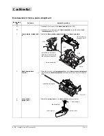
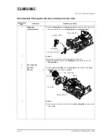
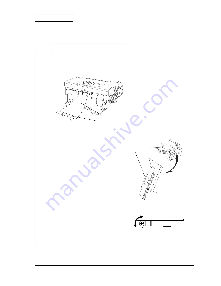
1
❏
Connect the FFC terminal No.12 to an
oscilloscope to display the output power voltage
of the B.M. detector on the oscilloscope screen.
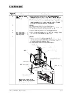
2
❏
Input DC5 V to the FFC terminal No. 13.
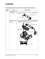
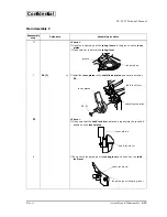
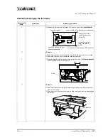
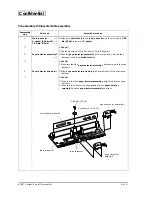
3.
❏
Insert a “Kodak Gray Card” into the paper
entrance.
(“Kodak Gray Card”: A commercially available
card for adjusting exposure.)
❏
Make sure that the gray side of the card is inserted
along the
paper guide
which the
B.M. detector
sub-assembly
is installed.
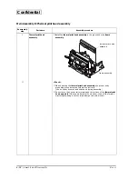
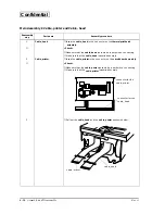
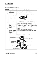
4.
❏
Adjust the output power voltage of the
B.M.
detector
at 1.74 V using the variable resistor on
the
circuit board assembly
.
❏
Turn the slot on the variable resistor to the right
and the left with a tool such as a flat-head driver,
to adjust the output power voltage.
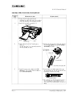
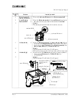
❏
If the reflectance of black marks on the paper is
over 10%, adjust the output voltage to 2 V or
more with a 25% or less reflectance for the black
marks.
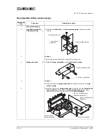
.....13 12 11 10 .....
NO.1
NO.15
circuit board
FFC
oscilloscope
DC5 V
GND
B.M. detector
sub-assembly
gray side of the gray card
paper guide
<Cross-section>
variable resistor


