GENERAL DESCRIPTION
Rev. A
1-
15
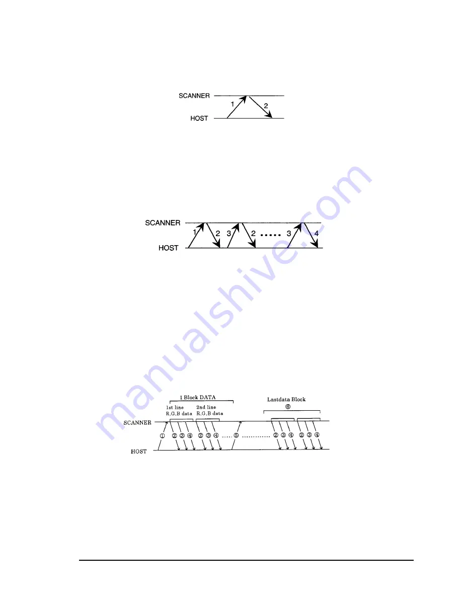
1.4.4 Data Handshaking Procedures
This section describes data handshaking procedures.
1.4.4.1 Inquiry Data
The type of data is determined by the control code (scanner ID, scanner status, etc.).
Step 1:
Control code sent from host computer.
Step 2:
Data received from scanner.
1.4.4.2 Monochrome Image Data Transfer
Image data is sent as a faster Or a block of data. (Refer to section 1.4.3, Data Structure.)
Step 1:
Control code (ESC G) sent from host computer.
Step 2:
Image data received from scanner.
Step 3:
Response sent from host computer:.
ACK (06h): Continue and send next data.
CAN (18h): Abort.
Step 4:
Last image data received from scanner.
Note: The host computer should not send an ACK (06h) code after receiving the last image
data.
1.4.4.3 Color Image Data Transfer: Line Sequence Mode (block transfer mode)
Step 1:
Control code from the host computer.
Step 2:
The Data-Block(G or R) from the scanner.
Step 3:
The Data-Block(R or G) from the scanner.
Step 4:
The Data-Block(Blue) from the scanner.
Step 5:
Response from the host computer.
ACK( 06H ): Continue and send the next data
CAN(18H ): Abort
Step 6:
The last Data-Block
Note: The host computer should not Send back ACK(06H) after receiving the last Data-Block.
Figure 1-11. Data Inquiry
Figure 1-12. Monochrome Image Data Transfer
Figure 1-13. Color Image Data Transfer: Line Sequence Mode (block transfer mode)
Summary of Contents for FILMSCAN 200
Page 1: ...EPSON FILM SCANNER FilmScan 200 SERVICE MANUAL SEIKO EPSON CORPORATION 4007375 ...
Page 5: ...v REVISION SHEET Revision Issued Data Contents Rev A FEBRUARY 28 1997 First issue ...
Page 8: ...EPSON SEIKO EPSON CORPORATION ...
Page 75: ...CHAPTER 4 ADJUSTMENT No adjustment is required in this product ...
Page 85: ...CHAPTER 6 MAINTENENCE 6 1 MAINTENENCE 6 1 6 2 LUBRICATION 6 1 ...
Page 86: ...APPENDIX A 1 CONNECTOR PIN ASSIGNMENTS 1 A 2 EXPLOED DIAGRAM 8 ...
Page 88: ...FilmScan 200 Rev A A 2 Figure A 2 Cable Connection SCSI Model ...
Page 95: ...APPENDIX Rev A A 9 Figure A 4 FilmScan 200 Bi D Model Exploded Diagram 2 2 ...
Page 96: ...FilmScan 200 Rev A A 10 Figure A 5 FilmScan 200 SCSI Model Exploded Diagram 1 2 ...
Page 97: ...APPENDIX Rev A A 11 Figure A 6 FilmScan 200 SCSI Model Exploded Diagram 2 2 ...
Page 98: ...FilmScan 200 Rev A A 12 Figure A 7 APS Holder option Exploded Diagram ...
Page 100: ...FilmScan 200 Rev A 6 2 Shaft 1 G 36 1 G 36 Figure 6 1 Lubrication Points ...


