OPERATING PRINCIPLES
Rev. A
2-15
2.3.4.1 Main Scan Motor Drive Circuit
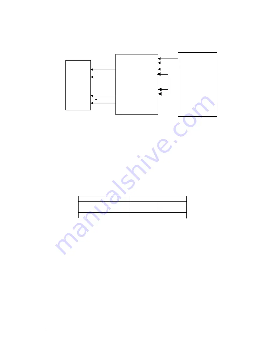
Figure 2-19 is a block diagram of the main scan motor drive circuit.
Table 2-7 indicates the relationship of the input and output excitation phase data of the M54670P (IC13)
motor driver.
Input
Output
IN A
IN B
A
B
H
L
H
L
L
H
L
H
PHA
I1 A/B
PC0
PC1
PD0
CPU
HD643003
(IC8)
01A
01B
02A
02B
A
B
A
B
M54670P
(IC13)
Main Scan
Motor
PHB
I0 A/B
Figure 2-19. Main Scan Motor Drive Circuit
Table 2-7. M54670P (IC13) Input and Output. Motor Excitation Sequence
Summary of Contents for FILMSCAN 200
Page 1: ...EPSON FILM SCANNER FilmScan 200 SERVICE MANUAL SEIKO EPSON CORPORATION 4007375 ...
Page 5: ...v REVISION SHEET Revision Issued Data Contents Rev A FEBRUARY 28 1997 First issue ...
Page 8: ...EPSON SEIKO EPSON CORPORATION ...
Page 75: ...CHAPTER 4 ADJUSTMENT No adjustment is required in this product ...
Page 85: ...CHAPTER 6 MAINTENENCE 6 1 MAINTENENCE 6 1 6 2 LUBRICATION 6 1 ...
Page 86: ...APPENDIX A 1 CONNECTOR PIN ASSIGNMENTS 1 A 2 EXPLOED DIAGRAM 8 ...
Page 88: ...FilmScan 200 Rev A A 2 Figure A 2 Cable Connection SCSI Model ...
Page 95: ...APPENDIX Rev A A 9 Figure A 4 FilmScan 200 Bi D Model Exploded Diagram 2 2 ...
Page 96: ...FilmScan 200 Rev A A 10 Figure A 5 FilmScan 200 SCSI Model Exploded Diagram 1 2 ...
Page 97: ...APPENDIX Rev A A 11 Figure A 6 FilmScan 200 SCSI Model Exploded Diagram 2 2 ...
Page 98: ...FilmScan 200 Rev A A 12 Figure A 7 APS Holder option Exploded Diagram ...
Page 100: ...FilmScan 200 Rev A 6 2 Shaft 1 G 36 1 G 36 Figure 6 1 Lubrication Points ...


