DISASSEMBLY AND ASSEMBLY
Rev. A
3-5
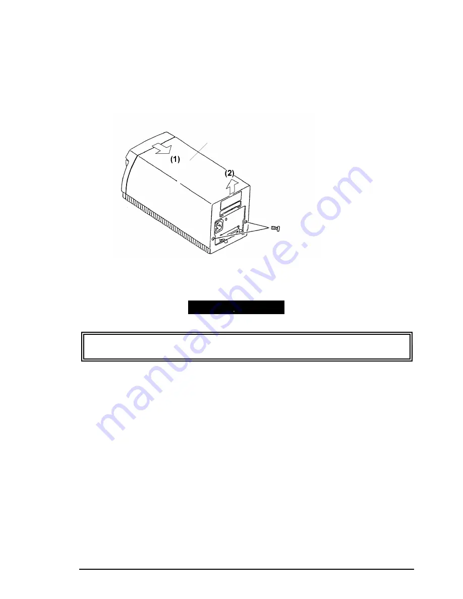
3.2.2 Upper Case Removal
Step 1:
Remove the two C.B (M3 x 6) screws and remove the upper case with the following steps (1)
and (2).
Be sure that the inside of cables should be closed correctly by the upper case.
Apply the Screw-lock when installing the two screws.
Upper Case
Figure 3-2. Upper Case Removal
ASSEMBLING POINT
Summary of Contents for FILMSCAN 200
Page 1: ...EPSON FILM SCANNER FilmScan 200 SERVICE MANUAL SEIKO EPSON CORPORATION 4007375 ...
Page 5: ...v REVISION SHEET Revision Issued Data Contents Rev A FEBRUARY 28 1997 First issue ...
Page 8: ...EPSON SEIKO EPSON CORPORATION ...
Page 75: ...CHAPTER 4 ADJUSTMENT No adjustment is required in this product ...
Page 85: ...CHAPTER 6 MAINTENENCE 6 1 MAINTENENCE 6 1 6 2 LUBRICATION 6 1 ...
Page 86: ...APPENDIX A 1 CONNECTOR PIN ASSIGNMENTS 1 A 2 EXPLOED DIAGRAM 8 ...
Page 88: ...FilmScan 200 Rev A A 2 Figure A 2 Cable Connection SCSI Model ...
Page 95: ...APPENDIX Rev A A 9 Figure A 4 FilmScan 200 Bi D Model Exploded Diagram 2 2 ...
Page 96: ...FilmScan 200 Rev A A 10 Figure A 5 FilmScan 200 SCSI Model Exploded Diagram 1 2 ...
Page 97: ...APPENDIX Rev A A 11 Figure A 6 FilmScan 200 SCSI Model Exploded Diagram 2 2 ...
Page 98: ...FilmScan 200 Rev A A 12 Figure A 7 APS Holder option Exploded Diagram ...
Page 100: ...FilmScan 200 Rev A 6 2 Shaft 1 G 36 1 G 36 Figure 6 1 Lubrication Points ...


