FilmScan 200
Rev. A
3-10
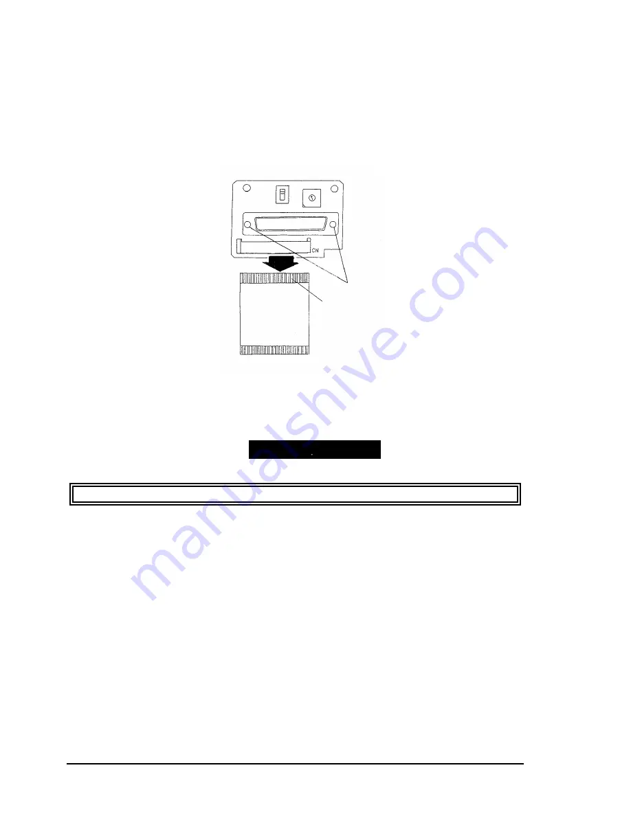
3.2.6 Sub Board Removal (SCSI Model Only)
Step 1:
Remove the upper case (Refer to section 3.2.2.)
Step 2:
Loosen the three CB (M3 x 6) screws that fastens on the inverter board (Refer to section
3.2.4. Inverter Board.)
Step 3:
Remove the shield plate C.
Step 4:
Remove the two hexagonal nut-screws.
Step 5:
Remove the FFC cable from the sub board then take the sub board away.
Apply the screw-lock when installing the two hexagonal nut screws.
Hexagonal
Screw
FFC
Figure 3-10. Sub Board Removal
ASSEMBLING POINT
Summary of Contents for FILMSCAN 200
Page 1: ...EPSON FILM SCANNER FilmScan 200 SERVICE MANUAL SEIKO EPSON CORPORATION 4007375 ...
Page 5: ...v REVISION SHEET Revision Issued Data Contents Rev A FEBRUARY 28 1997 First issue ...
Page 8: ...EPSON SEIKO EPSON CORPORATION ...
Page 75: ...CHAPTER 4 ADJUSTMENT No adjustment is required in this product ...
Page 85: ...CHAPTER 6 MAINTENENCE 6 1 MAINTENENCE 6 1 6 2 LUBRICATION 6 1 ...
Page 86: ...APPENDIX A 1 CONNECTOR PIN ASSIGNMENTS 1 A 2 EXPLOED DIAGRAM 8 ...
Page 88: ...FilmScan 200 Rev A A 2 Figure A 2 Cable Connection SCSI Model ...
Page 95: ...APPENDIX Rev A A 9 Figure A 4 FilmScan 200 Bi D Model Exploded Diagram 2 2 ...
Page 96: ...FilmScan 200 Rev A A 10 Figure A 5 FilmScan 200 SCSI Model Exploded Diagram 1 2 ...
Page 97: ...APPENDIX Rev A A 11 Figure A 6 FilmScan 200 SCSI Model Exploded Diagram 2 2 ...
Page 98: ...FilmScan 200 Rev A A 12 Figure A 7 APS Holder option Exploded Diagram ...
Page 100: ...FilmScan 200 Rev A 6 2 Shaft 1 G 36 1 G 36 Figure 6 1 Lubrication Points ...


