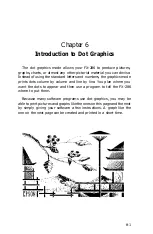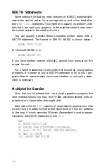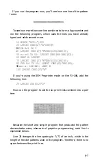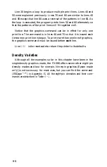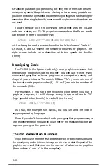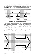
You should plan your figure with dots on graph paper, but before
beginning to place the dots, you must decide which graphics density
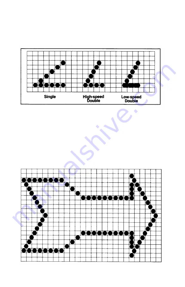
you want. Figure 6-3 shows the differences between the three most-
used graphics modes so that you can choose the one you want.
Figure 6-3. Designing in different densities
In this figure you can see the main rules for graphic design in the
three densities. In single density no dots can be placed on vertical
lines. In high-speed double density dots can be placed on vertical lines,
but no dots can overlap. In low-speed double density dots can be
placed on vertical lines and they can overlap.
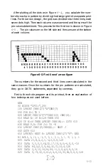
Now look at the figure designed for high-speed double density. It
should point you in the right direction for your own designs.
Figure
6-4.
Arrow design
6-12
Summary of Contents for FX-286 - Impact Printer
Page 1: ......
Page 2: ......
Page 35: ......
Page 40: ...2 4 ...
Page 48: ...3 8 ...
Page 56: ...4 8 ...
Page 91: ...6 16 ...
Page 118: ...C 10 ...
Page 133: ...Epson Mode Commands G 5 ...
Page 134: ...G 6 ...
Page 166: ...H 4 ...
Page 173: ...International Character Width Table Roman characters Italic characters I 7 ...
Page 174: ...I 8 ...
Page 180: ...J 6 ...
Page 181: ...IBM Proprinter Mode Commands J 7 ...
Page 182: ...J 8 ...
Page 202: ...J 28 ...
Page 208: ...K 6 ...
Page 216: ......
Page 220: ...IBM Mode See Appendix J for detailed explanations of codes Character Width Pitch ...
Page 221: ...Notes ...
Page 223: ......

