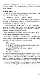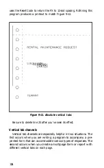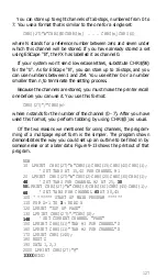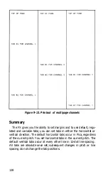
A final multiplication:
480
main columns
X
792
rows
gives you a grand total of
380,160
dot positions per FX-80 page. And
that doesn’t even take into account intermediate columns, the
FX-100’s ability to print 136 Pica matrixes, or both models’ ability to
use graphics density settings to increase the number of dots across the
page and microscopic line spacing to increase the number of dots
down the page.
Since there is a huge number of such dot positions on each page, this
sounds like a giant task. It won’t be, however, because we’ll give you
methods to shorten the time and steps to good graphics design.
Print Head
Printing high-resolution graphics on the FX requires a mode that is
very different from the text modes. In any of the several versions of
Graphics Mode, none of the predefined characters or symbols in the
printer’s memory are used. Instead, you create the patterns of dots
that are printed. Thus, you control where and when each and every
dot is printed.
To do this, you look at the page as a series of dot columns, arranged
in rows. For each column position on a print line, the print head
impresses the pattern of dots that you have specified. Before you can
start designing these patterns, however, you need to know a little
more about the way the print head works.
Even though there are nine pins on the print head, each column can
be only eight dots high. That’s because printer/computer communica-
tions are based on eight data lines, with each of the top eight pins of
the print head corresponding to one of the eight lines. So each sweep
of the head prints eight or fewer dots, depending on your computer
system and your specifications (see Figure 10-1).
Seven-bit systems can control only the middle seven pins. Because
we want users of such systems to be able to use these programs, we
rarely put the top pin to work in the programs that follow. When we
do, we tell you so.
132
Summary of Contents for FX-80
Page 1: ......
Page 22: ......
Page 23: ......
Page 26: ......
Page 31: ...Figure 1 1 The FX 80 and FX 100 printers 14 ...
Page 32: ...Figure 1 2 Printer parts 1 5 ...
Page 38: ...Figure 1 8 DIP switch vent 21 ...
Page 42: ...Figure 1 11 Ribbon insertion 25 ...
Page 51: ...Figure 1 20 Paper thickness adjustment 34 ...
Page 85: ......
Page 92: ......
Page 95: ......
Page 97: ...80 ...
Page 109: ......
Page 117: ...Figure 7 3 Staggering STAIR STEPS 100 ...
Page 119: ...Table 7 1 Line spacing commands 102 ...
Page 129: ...112 ...
Page 147: ...130 ...
Page 181: ...Figure 12 4 Corner of the FX 80 design ...
Page 189: ...Figure 12 10 Most distinct version Figure 12 11 Reversed version 172 ...
Page 215: ...198 ...
Page 231: ...214 ...
Page 249: ......
Page 269: ......
Page 272: ...iv ...
Page 283: ......
Page 290: ......
Page 305: ...282 ...
Page 311: ...288 ...
Page 323: ...300 ...
Page 339: ......
Page 343: ...320 ...
Page 349: ...326 ...
Page 353: ...330 ...
Page 354: ...Schematic 331 ...


