M O D E # 0
M O D E # 1
M O D E # 2
M O D E # 3
M O D E # 4
M O D E # 5
M O D E # 6
Figure 11-4. Seven density modes
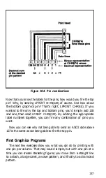
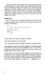
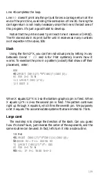
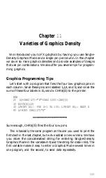
Figure 11-4 displays all seven of the FX modes that affect graphics
density. Table 11-1 describes them.
More Graphics Programming Tips
The next two sections discuss two modes that the FX offers to help
you solve potential graphics problems. A reassigning code allows you
to change the density for graphics programs
that
use one of the four
alternate codes. The 9-pin Graphics Mode allows you to use all nine
pins on each line and thus speed up screen dumps.
Reassigning alternate graphics codes
The FX provides a command to reassign one of the alternate
graphics codes-K, L, Y, or Z-so that it represents any other of the
seven Graphics Modes. The command and its format are:
LPRINT CHR$(27)"?s"CHR(n);
where s is one of the four symbols, K, L, Y, or Z, and n is one of the
numbers used with the ESCape " *" command, 0 to 6. There are sev-
eral instances in which you may use this sequence.
The first occurs if you have written a program to be printed in
one
Graphics Mode and now want to print it in another. If you have used
concatenation to store your Graphics command strings in one short
character string, that will not be difficult. You can simply change the
mode number or alternate code in the definition of the character
string.
In the program for Figure
11-4,
for example, you did this in line 20
by storing the Graphics Mode command sequence in A$ and making
150
Summary of Contents for FX-80
Page 1: ......
Page 22: ......
Page 23: ......
Page 26: ......
Page 31: ...Figure 1 1 The FX 80 and FX 100 printers 14 ...
Page 32: ...Figure 1 2 Printer parts 1 5 ...
Page 38: ...Figure 1 8 DIP switch vent 21 ...
Page 42: ...Figure 1 11 Ribbon insertion 25 ...
Page 51: ...Figure 1 20 Paper thickness adjustment 34 ...
Page 85: ......
Page 92: ......
Page 95: ......
Page 97: ...80 ...
Page 109: ......
Page 117: ...Figure 7 3 Staggering STAIR STEPS 100 ...
Page 119: ...Table 7 1 Line spacing commands 102 ...
Page 129: ...112 ...
Page 147: ...130 ...
Page 181: ...Figure 12 4 Corner of the FX 80 design ...
Page 189: ...Figure 12 10 Most distinct version Figure 12 11 Reversed version 172 ...
Page 215: ...198 ...
Page 231: ...214 ...
Page 249: ......
Page 269: ......
Page 272: ...iv ...
Page 283: ......
Page 290: ......
Page 305: ...282 ...
Page 311: ...288 ...
Page 323: ...300 ...
Page 339: ......
Page 343: ...320 ...
Page 349: ...326 ...
Page 353: ...330 ...
Page 354: ...Schematic 331 ...


