background image

Summary of Contents for FX Series

Page 1: ...11 I 1 r EPSON FX RX MX PRINTERS Product Support Supplement The Centre for Computing History ff www CompulingHistoiy org uk ...

Page 2: ...0P89074 FEBRUARY 1986 Prepared by Curriculum Development Service s XICTMD Service Training XEROX Copyright 1986 by Xerox Corporation Allrights reserved Epson FX RX and MX are registered trademarks of Epson America Inc PRINCIPLES OF OPERATION 1 WIRING DATA ...

Page 3: ...INTRODUCTION Introduction ii How to use this Manual ii 1 PRINCIPLES OF OPERATION 1 1 Principles of Operation 1 1 2 WIRING DATA 2 1 Introduction 2 1 2 2 FX 85 185 2 2 2 3 FX 80 100 2 6 2 4 RX 80 100 2 10 JiSy 2 5 MX 80 100 2 13 ...

Page 4: ...ox Service Center leaa technicians or service representatives HOW TO USE THIS MANUAL Start with the Product Support Manual If the Printer has a unique problem that the PSM does not support then refer to the appropriate Principles of Operation Electrical Description or Wiring section of this manual The schematic diagrams are provided to assist you in isolating components that are field replaceable ...

Page 5: ...home position i e the left end of the platen This signal serves as a reference signal for the printing operation Print Timing Sensor PTS The PTS sensor mechanism consists of the sensor and a sensor disk located on the shaft of the carriage motor The PTS signal is generated in order to coordinate carriage speed with firing of the dot wires allowing adequate time for the print operation to be perfor...

Page 6: ...ot wires housed in the print head 1 2 EPSON PRINTERS Printing Operation When the head driving coil for a dot wire isenergized the actuating plate engaaed at one end of the dot wire is attacheclto the iron core driving the dot wore toward the platen The dot wire thus driven strikes the ribbon pressing it against the paper on the platen assembly and causing a dot to be imprinted When the head drivin...

Page 7: ...g and paper holding rollers Paper support roller Paper feed roller Platen gear Platen Paper feed gear Fig 1 4 Friction Feed Mechanism Paper tead motor 1 3 PRINCIPLES OF OPERATION Pin Platen Feed System For Continuous Business Forms 9 5 and 10 Inches in Width Model 3510 only In the pin platen feed system paper is held in place on platen sprocket pins on the platen shaft When the paper feed pulse mo...

Page 8: ...a cartridge ribbon and a ribbon feeding mechanism which is set on a belt tension plate assembly The right or left motion of the timing belt is transmitted to the ribbon drive gear through the gears on the belt tension plate Due to conformation of the gear train the ribbon is always fed in a counter clockwise direction When the ribbon feed roller is driven by the ribbon drive gear the continuous lo...

Page 9: ... F ircuU_Bo _j Fig 1 8 Block Diagram of Power Circuit FX 8S 185 105 fXEXT O 5V O 24V Vp O 12V O cBV O VKp o Vkc AC12V 1 5 Voltago 24V VPI 5V Vcc lav _AC12V Vkc 6V Vx P t5V PRINCIPLES OF OPERATION TABLE 1 2 Types and Applications of Power Application CD CorriBO motor driva Paper feed motor driva D Print solenoid drive i li iertaceoption circuit board power t T FXMB logiccircuitdrive X Carnagemotor ...

Page 10: ...the printer are eliminated by this noise prevention circuit Capacitors C2 and C3 are not used for the 120 version sw Fl L O d j SOOajH C2 i 700P C1 dp O lpF CN1 C3 iz 4700P N O N O Fig 1 9 Fuse and Filter Circuit 1 6 EPSON PRINTERS Power Transformer In the Printer the power transformer changes the AC input into AC 26V and 12VAC through the filter circuit and supplies necessary voltages to the cont...

Page 11: ... or deceleration Control is achieve by comparing the time set by the firmware and the PTS signal detected when the carriage operates When driving the carriage from left to right TABLE 1 3 CARRIAGE MOTOR STEP SEQUENCE CW STEP A phase B phase C phase D phase 1 ON OFF OFF ON 2 ON OFF ON OFF 3 OFF ON ON OFF 4 OFF ON OFF ON When driving the carriage from right to left 1 7 PRINCIPLES OF OPERATION TABLE ...

Page 12: ...se C phase 0 phase 1 1 1 t 1 t Sat time Fig 1 12 Carriage Speed Too Slow 1 8 EPSON PRINTERS When the PTSSignal is detected earlier the the set time the phase selection is made at the leading edge of the PTS signal PTS Solenoid drive pulse A phase B phase C phase 0 phase n I t Set time Fig 1 13 Carriage Speed Too Fast nmr ROTOR imy O CRA O CRB O CMAS CMCD OCRD OCRC Fig 1 14 Carriage Motor Connectio...

Page 13: ... 1 c A 1 QQQO c O PFB O PFCM O PFD O PFC Fig 1 15 Paper Feed Motor Connections Paper feed in forward direction TABLE 1 5 PAPER FEED MOTOR STEP SEQUENCE CW STEP No A phase B phase C phase D phase 1 ON OFF ON OFF 2 ON OFF OFF ON 3 OFF ON ON OFF 4 OFF ON OFF ON 1 9 PRINCIPLES OF OPERATION TABLE 1 6 Paper Feed Motor Step Sequence CCW STEP No A phase B phase C phase D phase 1 ON OFF OFF ON 2 ON OFF ON ...

Page 14: ...Timing For the energization timing the PTSsignal which is generated when the carriage is operated is input to PCS of the main CPU The main CPU outputs a LOWsignal which has an energization pulse width Energizing Time Control The energizing time is controlled according to reference voltage Vt which is input to ANO of the main CPU Reference voltage Vt is normally factory adjusted by VRI to 2 5 V aga...

Page 15: ...ive pulse J L c 400 ws 10 iS 24V Fig 1 18 PTSand Drive Pulse Timing 1 11 Print Timing PTS signal Print solenoid 1 Print solenoid 2 Print solenoid 3 Print solenoid 4 Print solenoid 5 Print solenoid 6 Print solenoid 7 Print 1 Print 2 Print 3 Print 4 Print 5 Print 6 Print 7 PRINCIPLES OF OPERATION 1 L L Print solenotd dnvu pulM l j 1 i 1 1 1 I A w A W A w A w w A W w w 9 A w A w m Fig 1 19 Print Timi...

Page 16: ...me Position Sensor Detection System Output System Circuit Photo electric conversion Open collector See Fig 1 21 5V 200a vw I 5Ka 1 5 nn o wv 470P LS74 0 Q BB CL PTS aisnti Fig 1 21 HP Sensor Circuit Timing T Kgntl n tignal wav at point A HOMEiignil wave at point 81 Horn poiition Fig 1 22 First Dot Position EPSON PRINTERS O RtiS O KOMEugn Utdol ...

Page 17: ... on the main board to correct the carriage speed b Itisinput to the main CPU through IC 8Aon the circuit board to determine the print timmg c It latches the status of the home position 1 13 PE Paper End Sensor Detection system Svy itch rating Switch mode PRINCIPLES OF OPERATION Reed switch 10 50 mA 5VDC 5 See table 1 7 TABLE 1 7 Switch Mode Paper Switch Moda Presence OPEN Absence CLOSE Operation I...

Page 18: ... section includes signals and pin assignments relating to the various connectors providing electrical connectionsamong printer componentssuch as the printer mechanism the control circuit boarcC and the control panel Each model will be described individually 2 1 ...

Page 19: ... part of papar faad 4 Ounng pnntsr arror status 5 In OFF LINE suta A HIGHsignal indieataa that tha printar is out of papar Putlad up to 5V through 3 3 IlO rasiatanca 2 2 EPSON PRINTERS TABLE 2 1 cont Signal Pin No Ratum Pin No Signal Transmlttar Daacription 14 AUfb FEEDXT Host Computar With this signal baing at LOW la val tha papar is automatically fad ona Unaaftar printing 16 NC Notuaad 16 GNO LO...

Page 20: ...l Otit Bit 2 II DS SI In Otu Bit 8 Sanal Signal Input 11 04 In Oul 0 Mait4 12 AC12 Out 12VAC 12 OS In Oul Otit Bit S 13 R Out Raaat 13 Out Rud Oul Signll 14 ACI2 Out 12V 14 Sgf Out Rmci Signal IB 03 82 In Oaia Bit 3 Sit Rtia Salaci IS 24 Out 24V DC IS 6 Out BVOC IS 5 Oul 8V0C 17 02 81 In Otu Bit 2 Bil Rau Salact 17 A1 Oul Addcatt Bit 1 IS 24 Out 24V0C la A3 Dul Address 8it 3 19 01 8 7 In Otu Bit 1...

Page 21: ...TE Direction refers to the direction of signal flow as viewed from the control circuit board 2 4 EPSON PRINTERS Connector CN5 FX85 185 Use Exchange of control siqnals between the control circuit board and the print head and HOME HP sensor of the printer Mechanism 16 Pins TABLE 2 5 PIN ASSIGNMENT OF CN5 Pin No SIgnel Neme Direction Description of Signal 1 GND HOME HP Sensor GND 2 HOME In HOME HP Se...

Page 22: ...l 2 AC2 Orange lolsnoid 3 PELP Out Paper End LEDDrive Signal 3 AC3 Gray 12V AC for option inierfaca 4 ON LINE LP Out ON LINELEDDrive Signal 4 AC4 Gray S LF SW In LINEFEED Signal 6 FF SW In FORM FEEDSignal 7 ON LINE SW In ON OFF LINESwitching Signal 8 GL Logic Ground 2 5 NOTE Direction refers to the direction of signal flow as viewed from the control circuit board Connector CN8 FX85 185 Use Send si...

Page 23: ... of paper tt is LOW normally and becomes HIGH when paper Is gone 2 6 EPSON PRINTERS TABLE 2 9 cont 13 SLCT Out Pulled up to t SV through 3 3kn resistance 14 AUTO FEED XT In With this Signal being at LOW level the paper is automatically fed one line after pnnttng which is stan ed at pnnt buffer full or at the input of CR Carriage Return 15 NC Not used 16 0 V LOGIC GND level 17 CHASSIS GND Printer C...

Page 24: ...TRS Select 26 QL Ground NoM Oif ctloo nhn th dif ction of wonal Ho as vie d from th coniroJ circuit board 2 7 WIRING DATA Connector CN3 FX 80 100 Use This optional connector is used at future extension of specifications TABLE 2 11 PIN ASSIGNMENT OF CN3 Pin No Signal Name Oiractton Oeacnptlon o Signti 1 AO Out AddtM4 Bit 0 2 A2 Out AddriM Bit 2 3 A4 Out Addrau Bit 4 4 Ae Out AddrcMBilS 9 A8 Out Add...

Page 25: ...ing Signal 17 GP PTS Sensor GNO 18 OP PTS Sensor Shield Not Oiractlon r a o ttM tlroction of sisnal Kow aa viewM from the control circuit boanl 2 8 EPSON PRINTERS Connector CN5 FX 80 100 Use This connector is used for exchange of control signals between the control circuit board and the print head and HOME HP sensor of Printer Mechanism TABLE 2 13 PIN ASSIGNMENT OF CN5 Pin No Signs Namo Direction ...

Page 26: ...ion Oaacription of Signal 1 5 Out 0 amp Onva Powar 2 RDYLP Out READYLEOOrtva Signal 3 PEtJ Out Papar End LEO Oriva Signal 4 ON LINE LP Out ON LINE LEO Orlva Signal 9 LFSW In UNE FEED Signal 6 FFSW In FORM FEED Signal 7 ON UNE SW In ON OFF UNE Switching Signal a QL tu gic Ground Nata DUvctton retara to tn dtraction of sional flow u vitwad from tfw corM circut board Connector CN8 FX 80 100 Use This ...

Page 27: ...rinter cannot receive data 2 10 EPSON PRINTERS TABLE 2 17 cont A LOW signal indicates that the printer can receive data The signal becomes HIGH in the following cases 1 During data entry 2 During printing operation and part of head carrier operation 3 Durmg part of paper feed 4 During printer error status 5 In OFF LINE state 12 30 PE Printei A HIGH signal indicates that tfra printer is out of pape...

Page 28: ...t Erior 2 PF Out Paper End 3 07 In Data Bit 7 4 RDV BUSYl Out Ready ii D6 in Data Bit 6 6 AC3 Out Acknowledge 7 05 PARDlS In Data Bit 9 Panty OisaMa a INJT In Imtial 9 04 0 L In Data Bit 4 Odd Panty Select Even Panty Seioct 10 STB In StrotM 11 oe a In Data Bit B Serial Signal Inout 12 AC 12 Out rt2V AC 13 fS Out Reset 14 AC 12 Out 12 V AC IS D3 B2 tn Data Bit 3 Bit Rate Select le I 5V Out SV OC 17...

Page 29: ...LFC Out LF Motor C Phase 11 CRO Out CR Motor D Phase 12 150 Out LF Motor 0 Phase 13 5V Out rSV DC 14 PTS SHIELD In PTS Shield IS PTS In PTS Signal 16 Q LEO Out Ground LEO 17 QH In Ground HOME ia Home In HOME Signal 19 H3 Out Heed Pin 3 Orivtng Signal 20 H7 Out Head Pin 7 Driving Signal 21 HI Out Head Pin I Driving Signal 22 H5 Out Head Pin S Driving Signal 23 SOL Out Solenoid Drive Voltage 24 SOL ...

Page 30: ... tne printer tne cnassis GND and me iog c GND are isolated irom eacn other 16 NC 1 Not used 19 to 30 GND TWiSTEO PAiR RETURN Signal GND levei 2 13 WIRING DATA TABLE 2 21 cont S 4n4l PiA No Roiurn Pin No Signal Oi ttClion Oescnpiion 31 iRlT In wnen the level ol mis signal becomes LOW me piiniei controller is lesei to its initial state and me print Duller is cleared This signal is normally at HIGH l...

Page 31: ...gnal Name Oescripiibn ot Signal Direction 1 Erroi Out 2 Paper End Out 3 07 1 Oaia Bit 7 in 4 ffCv BUSY Ready Out 5 06 1Oaia Bii 6 in 6 aCk AcKnowiedge Out 7 05 PAfl OlS Oaid Bii 5 Patity Oisaoie In 8 iNlT inilial In 9 D4 0 E Oaia Bii 4 0 10 Panty Seiect Even Parity Select In 10 5TB Sirooe 1 in 11 08 31 Oata Bit 8 Seriai Signal input in 12 12 12V AC Out 13 7T Reset Out 14 1 12 12V AC Out 15 03 B2 O...

Page 32: ...isiers to mo diteciion ol signal How as viewM itom tne co tio ciicu t boaia 2 15 WIRING DATA Connector CN5 MX 80 100 Use Two CN5 connectors one with male contacts and the other with female contacts are used to supply control signals between the control circuit board and the driver circuit board of the MX TABLE 2 25 PIN ASSIGNMENT OF CN5 Connector Pin No Signal Name Description ol Signal Direction ...

Page 33: ...n 1 10 SOL Solenoid common line 24V in i n SOL Solenoid comrnon line t 24V In 12 V 5 5V In 13 SCR Carnage Sletiper Motor Current Lnmiting Signal in u SLF Paper Feed Stepper Motor Current Limiting Signal In 15 6LE0 Ground level 16 GPE Ground level i 17 GR Ground level 16 PE Paper End Signal irom Printer Mecnamtm Oul j 19 PTS Timing Signal Irom Printer Mecnanism Oui 20 RS Reset Signal from Printer M...

Page 34: ...s Part 2 3 20 3 11 FX 100 100 185 286 Printer Mechanism Components Part 1 3 22 3 12 FX 100 100 185 286 Printer Mechanism Components Part 2 3 13 FX 100 100 185 286 Printer Mechanism Components Part 3 3 14 MX 100 Covers and Electrical Components 3 15 MX 100 Printer Mechanism Components Part 1 3 16 MX 100 Printer Mechanism Components Part 2 RX 1 00 Q0 y COWfS no fciectrical Components RX 100 100 Prin...

Page 35: ...ere is however no guarantee that interference will not occur in a particular installation If equipment certified to meet Class B limits does cause interference to radio or television reception which can be determined by turning the equipment off and on the user is encouraged to try to correct the interference by one or more of the following measures a Reorient the receiving antenna b Relocate the ...

Page 36: ...s that effect those components Final Actions Contains the steps necessary to complete a service call General This section deals with general information about the printers maintenance procedures special tool requirements install checklists specifications supplies IClocations etc All service calls on the Epson printer should follow the sequence used in this manual That sequence is illustrated in Fi...

Page 37: ...ited Pi Pi Pi Peep Abnormally high voltage detected 1 2 EPSON PRINTER 1 3 INITIAL CHECKS 1 Sel up Turn printer povt er off disconnect the printer interface cable remove the ribboncartridge and remove anypaper from printer Move carriage to the center of its travel and turn printer power on 2 On the control panel the Power LED is on YES NO Proceed to RAP 2 1 On MX 80 and MX 100 proceed to setp4 I he...

Page 38: ...LF switch Turn power on Release switch when printer starts to print on MX 100 hold LF switch until 5 lines print Print operation is executed YES NO Proceed to RAP 2 9 SERVICE CALL PROCEDURES B I 10 One line of paper feed occurs for each line of print YES NO Proceed to RAP 2 7 11 Printing isof good quality for several consecutive lines see Figure 1 2 YES NO Proceed to RAP 2 9 01234567 01234567 my i...

Page 39: ...ity 1 4 13 One line of paper feed occurs for each line of print YES NO Proceed to RAP 2 7 EPSON PRINTER 14 Printing is of good quality for several consecutive lines see Figure 1 3 YES NO Proceed to RAP 2 9 15 Turn power off ensure that paper is in the printer then turn power on Press the FF FORM FEED switch and the LF LINE FEED switch alternately several times On rhp FX tftnof rniinH nrirf n p ipn...

Page 40: ... RAP 2 12 18 Press the FF FORM FEED switch once The paper is fed by one page YES NO Proceed to RAP 2 12 19 Turn power off Connect the printer to the host computer Turn power on Give the print instruction from the host to execute printing Print is normal YES NO I Proceed to RAP 2 13 20 Proceed to Final Actions SERVICE CALL PROCEDURES 1 5 ...

Page 41: ...Feed Checkout Page 2 21 22 Tables 2 4 and 2 5 are on fold out sheets for easy reference List of figures FIGURE 2 1 FIGURE 2 2 FIGURE 2 3 FIGURE 2 4 FIGURE 2 5 Page 2 3 Page 2 3 Page 2 5 Page 2 10 Page 2 23 24 FIGURE 2 5 is on a fold out sheet for easy reference 2 1 REPAIR ANALYSIS PROCEDURES TABLE 2 1 Printer Configuration Model Main Board Daughter Board Filter Board Printer FX 80 FX80 FMBD SUMI s...

Page 42: ... poweron andmeasurethe Transformer output voltagesonthe plug Voltages are correct YES NO I Replace transformer Procedure 4 3 Return to the initial checks and continue B 2 2 EPSON PRINTER Turn power off Disconnect printer mechanism Procedure 4 7 from the main board Connect transformer plug to the main board Turn power on Measure the transformer output voltages See TABLE 2 4 for values and Figure 2 ...

Page 43: ...2 1 Filter Boards Transformer input plug Transformer input plug REPAIR ANALYSIS PROCEDURES 1 2345678 38 2B MB HMPT BOARD MX 80 100 RXMCBOARD RX80 100 Transformer output plug Pin 4 FXMB BOARD Pin3 FX80 80 100 100 85 185 k2v FXMM BOARD Pin l FX 286 FMBD BOARD FX80 100 Transformer output plug 1 u Transformer output plug Figure 2 2 Control Boards ...

Page 44: ...o the initial checkout and continue Replace filter board Procedure 4 4 Return to the initial checks and continue 2 4 EPSON PRINTER Turn power off Disconnect print head from printer mechanism Procedure 4 8 Connect printer mechanism to the main board Turn power on Observe the Fuse the fuse is blown YES NO Turn power off Connect print head Turn power on Observe the Fuse the fuse is blown YES NO Turn ...

Page 45: ...rn to the initial checks and continue 2 On FX286 replace IC9B Procedure 4 15 On FX 85 185 replace IC98 Procedure 4 15 On FX80 80 100 100 replace IC98 Procedure 4 15 On RX80 80FT 7100 100 replace the main board Procedure 4 6 Problem is solved YES NO Replace main board Procedure 4 6 Return to the initial checks and continue 2 5 REPAIR ANALYSIS PROCEDURES Buzzer MPEL MX 80 100 RX 80 8 100 1 23456789 ...

Page 46: ...O Refer to the GENERAL section and check the switch settings on the main board Problem is solved YES NO Turn power off Measure resistance of PE switch Actuate and deactuate the switch to ensure that the readings change See TABLE 2 4 for values and location Readings are correct YES NO 1 Replace PEswitch Procedure 4 14 Return to the initial checks and continue 2 6 F Replace main board Procedure 4 6 ...

Page 47: ...rn power on The carriage movesto the right and vibrates YES NO Follow TABLE2 2 to change the replaceable parts Problem is solved YES NO I i H J 2 7 REPAIR ANALYSIS PROCEDURES TABLE 2 2 Carriage Operation Replacement Order To use this table A Find the prmter you are working on in the table B Follow the replacement order by replacing the listed Items one at a time C After each replacement try the pr...

Page 48: ...arts Problem is solved YES NO i Replace carriage motor Procedure 4 10 Problem is solved YES NO i Follow path J above 5 Return to the initial checks and continue 2 8 EPSON PRINTER 2 6 INCORRECT PAPER OUT TONES 1 Remove top cover Procedure 4 1 Reconnect control panel Procedure 4 2 Check paper out switch actuation Insure thatswitch is mounted correctly and paper is inserted correctly Switch actuates ...

Page 49: ...Replace main board Procedure 4 6 Problem is solved YES NO Replace printer mechanism Procedure 4 7 I 2 Return to the initial checks and continue 2 9 REPAIR ANALYSIS PROCEDURES 2 8 INCORRECT CONTROL PANEL STATUS 1 Remove lop cover Procedure 4 1 Reconnect control panel Procedure 4 2 Check that the connector between the main board and control panel is properly connected Cable is properly connected and...

Page 50: ...rinted are dark YES NO Ribbon advances when the carriage moves left and right YES NO Proceed to RAP 2 11 Ribbon is fresh ink is not dried out YES NO Replace ribbon with a new ribbon Return to the initial checks and continue 3 Check and adjust ifnecessary the platen to printhead gap and ribbonmask Procedure 4 8 1 4 8 2 Problem is solved YES NO I I 2 10 Parts of characters are missing YES NO Adjust ...

Page 51: ... Clean with film remover if necessary 3 Check the print head dot wires The wires are all straight and un damaged YES NO Replace the Print head Procedure 4 8 Return to the initial checks and continue 4 Follow TABLE 2 3 on page 2 12 to change the replaceable parts Problem is solved YES NO Replace Print head Procedure 4 8 I 5 Return to the initial checks and continue 2 11 REPAIR ANALYSIS PROCEDURES C...

Page 52: ...MI Note The SUMI board may be replaced by a Slave CPUchip FX 80 100 IC3B IC9B IC4A ICSA FMBD board MX 80 MDRI IC8B IC9B ICIC ICIB HMTP board board MX 100 MDRI IC8B IC9B ICIC ICIB IC2B IC3B HMPT board board RX 80 100 80FT 100 ICSA IC8B RXMC board 2 12 EPSON PRINTER 2 11 RIBBON NOT ADVANCING 1 Remove ribbon from prmier Turn knob on ribbon cartridge in direction of arrow Ribbon moves as knob is turne...

Page 53: ...l checks and continue 2 Replace main board Procedure 4 6 Problem is solved YES NO i Replacecontrol panel Procedure 4 2 3 Return to the initial checks and continue 2 13 REPAIR ANALYSIS PROCEDURES 2 13 INCORRECT OPERATION WITH HOST COMPUTER 1 Remove top cover Procedure4 1 Reconnect control panel Procedure 4 2 Insure that all the switch settings on the main board are correct Adjust if necessary Probl...

Page 54: ...iubsection for each model printer If there is a repair or adjustment procedure for a specific part it is noted on the part illustration The k6y for identifying repair and adjustment procedures is below No repair or adjustment procedure Repair procedure Adjustment procedure Repair and adjustment procedure Y PARTS LISTS 3 1 ...

Page 55: ...R THE FX 80 O 16 547N137 Y440501000 TRANSFORMER TABLE 3 3 FOR THE FX 80 17 140N272 Y440215000 FFIL BOARD UNIT TABLE 3 5 FOR THE FX 85 18 117N57 Y422301001 POWER CABLE 19 108N6 X502060020 FUSE 250V 2 53N2 X440755400 REGULATOR 1C1 20 91N46 Y422030001 EARTH PLATE D 3 528N1 X400040161 PROM 2A 3A UPD4016 D 1 FX 80 21 91N47 Y426030001 EARTH PLATE B 4 547N2ia X630206400 EPROM HOLDING CLIP 22 91N142 Y4400...

Page 56: ...EPSON PRINTERS PARTS LISTS ...

Page 57: ...SEMBLY 7 20N12 F303017000 BELT DRIVEN PULLEY 8 13N14 B210151490 BALLBEARING 9 9N52 F303005020 HEAD LOCK LEVER SPRING 10 23N30 F315017020 FELT RING 11 84N54 F315018000 CARRIAGE ASSEMBLY 12 108N62 F315021130 RIBBON MASK 13 84N58 F404100000 PRINT HEAD FX 80 130N101 F404110000 PRINT HEAD FX 85 14 23N6 F303014010 TIMING BELT A 15 20N13 F303018020 BELT DRIVEN PULLEY FLANGE 16 20N34 F303018010 BELT DRIVE...

Page 58: ...EPSON PRINTERS PARTS LISTS 18 3 5 ...

Page 59: ... 19N10 Y422020001 RUBBER PAD 8 140N24t Y435206200 FUSE AND FILTER BOARD 9 105N78 Y435501300 TRANSFORMER 10 117N57 Y422301001 POWER CORD 11 91N63 Y422034001 LOGO PLATE 12 101N118 Y435000001 UPPER CASE 13 110N55 Y445501000 PANEL SWITCH UNIT 14 22N38 Y43500800J SEPARATOR ROLLER 15 101N120 Y435007001 SEPARATOR RX 80 16 101N119 Y435004001 PRINTER COVER 17 547N119 Y435301000 CABLE SET 18 117N18 Y4223070...

Page 60: ...EPSON PRINTERS PARTS LISTS a 3 7 ...

Page 61: ...8150350111 E RING 8 84N44 F303006000 CARRIAGE 9 547N158 F404500000 PRINT HEAD 10 57N4 F303001092 RI880N MASK 11 26N37 8040450812 CP SCREW 12 112N9 F316016000 PAPER FEED MOTOR 13 7N32 F303001080 SPROCKET TRANSMISSION GEAR 14 9N53 8101250512 LEAF SPRING 15 84N47 F303009000 PAPER EMPTY BOARD ASSEMBLY 16 547N116 F303009021 PAPER EMPTY LEAD WIRE 17 547N120 F310011000 PAPER EMPTY LEVER ASSEMBLY 18 28N18...

Page 62: ...EPSON PRINTERS PARTS LISTS 19 18 Al n 3 9 ...

Page 63: ...50111 E RING 6 547N118 F303020020 PLANETARY PINION 7 26N35 8040301311 CP SCREW 8 23N6 F303014010 TIMING BELT 9 7N7 F303014020 RIBBON DRIVING GEAR 10 130N7 F303030000 HOME POSITION SENSOR 11 26N37 8040450812 CP SCREW 12 84N45 F316010000 PAPER GUIDE PLATED 13 20N12 F303017000 BELT DRIVEN PULLEY ASSEMBLY 14 130N6 F304059000 PTS SENSOR BOARD ASSEMBLY 15 84N43 F316014000 TIMING BELT MOTOR ASSEMBLY 16 1...

Page 64: ...EPSON PRINTERS PARTS LISTS f 3 11 ...

Page 65: ...ROCKET LOCK LEVER 5 29N9 F303011060 G PIN 6 26N46 B011401611 CP SCREW 7 7N4 F303011020 PAPER FEED SPROCKET 8 38N12 F303010020 PAPER GUIDE ROLLER 9 547N152 F304004020 BEARING 10 28N19 8150300811 E RING 11 9N56 8101251490 LEAF SPRING 12 7N59 F303013020 SPROCKET GEAR 13 29N12 B130103216 SPRING PIN 14 7N3 F303037010 RIGHT SPROCKET FRAME 15 2N37 F303037020 RIGHT PAPER HOLDING COVER 16 101N202 F30301001...

Page 66: ...EPSON PRINTERS PARTS LISTS 3 13 ...

Page 67: ... 10 2N38 Y422026001 FUSE AND FILTER BOARD COVER FOR IC CHIP PART NUMBERS AND COMPATIBILITY SEE 11 108N6 X502060020 FUSE 250V 2A TABLE 3 11 FOR THE MX 80 12 117N57 Y422301001 POWER CORD TABLE 3 12 FOR THE MX 80III 13 140N34 Y422203000 MPEL CIRCUIT BOARD UNIT 14 2N67 Y423003001 TOP COVER 29 140N33 Y422202000 MDRI CIRCUIT BOARD 15 14N12 Y422025001 SEPARATOR ROLLER 537N12 Y422800203 LSI MPU 9B 16 547N...

Page 68: ...EPSON PRINTERS PARTS LISTS ...

Page 69: ...47 F303009000 PAPER EMPTY BOARD ASSEMBLY 8 547N118 F303020020 PLANETARY PINION 33 110N56 A170202502 REED SWITCH 9 7N7 F303014020 RIBBON DRIVING GEAR 34 116N42 F303024000 TERMINAL BOARD ASSEMBLY 10 26N35 8040301311 CUP SCREW 11 130N7 F303030000 HOME POSITION SENSOR 12 32N13 F303021001 PAPER GUIDE PLATE A 13 130N6 F304059000 PTS SENSOR BOARD ASSEMBLY 14 84N7 F303027000 TIMING BELT MOTOR ASSEMBLY 15 ...

Page 70: ...EPSON PRINTERS PARTS LISTS m 3 17 ...

Page 71: ... 6 FOR IC CHIP PART NUMBERS AND COMPATIBILITY SEE TABLE 3 2 FOR THE FX 100 TABLE 3 4 FOR THE FX lOO TABLE 3 6 FOR THE FX 185 TABLE 3 7 FOR THE FX 286 TABLE 3 8 FOR THE FXEXT BOARD 2 46N18 Y441590000 3 547N142 F011402411 4 547N235 Y441004001 5 3N71 Y440010001 3N197 Y440068001 M 3560 PRINTER MECHANISM CP SCREW LOWERCASE PLATEN KNOB FX 100 PLATEN KNOB FX 185 EPSON PRINTERS NOTE 1 THE MAIN CIRCUIT BOA...

Page 72: ...i ...

Page 73: ...C CIRCUIT BOARD UNIT FX 286 11 547N147 F010104611 CP SCREW 12 101N127 Y440014001 BOARD COVER 13 14N17 Y441006001 SEPARATOR FX 100 101N331 Y441069001 SEPARATOR FX 185 14 101N224 Y441007001 TRACTOR COVER FX 100 2N276 Y441067001 TRAaOR COVER FX 185 15 547N138 Y440004101 PRINTER LID FX 100 46N19 Y441014001 PRINTER LID FX 185 16 101N193 Y441002001 TOP COVER FX 100 17 140N1119 Y492208000 FXEXT BOARD FX ...

Page 74: ...EPSON PRINTERS PARTS LISTS m ...

Page 75: ...D LOCK LEVER SPRING 13 23N30 F315017020 FELT RING 14 84N54 F315018000 CARRIAGE ASSEM8LY 15 57N4 F303001092 RI8B0N MASK 16 130N38 F404300000 PRINT HEAD FX 100 130N102 F404120000 PRINT HEAD FX 185 130N117 F410100000 PRINT HEAD FX 286 17 7N35 F315021070 PAPER FEEDING REDUCTION GEAR 18 9N59 F315062030 PAPER FEEDING SPRING 19 26N37 8040450812 CP SCREW 20 84N55 F315064000 PULSE MOTOR ASSEM8LY FX 100 185...

Page 76: ...EPSON PRINTERS PARTS LISTS Pm 3 23 ...

Page 77: ... F303020000 PLANETARY LEVER ASSEMBLY 7 26N35 B040301311 CUP SCREW 8 7N36 F315052010 RIBBON DRIVING GEAR 9 130N63 F317055000 HOME POSITION SENSOR 10 116N44 F317053000 TERMINAL BOARD ASSEMBLY 11 140N274 F315060000 PRINTING SIGNAL SENSOR BOARD ASSEMBLY 12 84N56 F315059000 CARRIAGE MOTOR ASSEMBLY FX 100 185 127N244 F328051000 CARRIAGE MOTOR ASSEMBLY FX 286 13 26N37 B040450812 CP SCREW 14 20N12 F303017...

Page 78: ...EPSON PRINTERS PARTS LISTS J 1 3 25 ...

Page 79: ...15101050 SPROCKET REDUCTION GEAR 7 28N16 B150300611 E RING 8 9N56 8101251490 LEAF SPRING 9 7N59 F303013020 SPROCKET GEAR 10 29N12 8130103216 SPRING PIN 11 547N152 F304004020 8EARING 12 7N3 F303037010 RIGHT SPROCKET FRAME 13 9N16 F303011040 PAPER HOLDING COVER SPRING 14 2N37 F303037020 RIGHT PAPER HOLDING COVER 15 11N53 F317101000 SPROCKET UNIT 16 2N36 F303036020 LEFT PAPER HOLDING COVER 17 7N2 F30...

Page 80: ...EPSON PRINTERS PARTS LISTS 3 27 ...

Page 81: ...027001 INSULATION 10 117N15 Y422306000 CABLE SET 844 26 117N18 Y422307000 GROUND WIRE 11 140N35 Y422204500 FUSE AND FILTER BOARD 27 117N16 Y422305000 CABLE SET 843 12 108N6 X502060020 FUSE 250V 2A 28 3N39 Y422015001 PLATEN KNOB 13 117N57 Y422301001 POWER CORD 39 9N17 X510360010 PLATEN KNOB SPRING 14 26N38 B040450711 CP SCREW 30 26N34 B040302811 CP SCREW 15 105N9 Y422501100 TRANSFORMER 31 SEEPROCED...

Page 82: ...EPSON PRINTERS PARTS LISTS J 3 29 ...

Page 83: ... RING 31 7N34 F304004010 PLATEN DRIVE GEAR 8 9N52 F303005020 HEAD LOCK LEVER SPRING 32 547N120 F310011000 PAPER EMPTY LEVER ASSEMBLY 9 23N7 F310057020 TIMING BELT 33 9N20 F303007020 PAPER EMPTY LEVER SPRING 127N144 F314053000 TIMING BELT MX 100 III 100 CPS 34 28N18 8150300311 E RING 10 117N15 Y422306000 CABLE SET 844 35 140N466 F310012000 PAPER EMPTY BOARD ASSEMBLY n 28N16 8150300611 E RING 36 110...

Page 84: ...EPSON PRINTERS PARTS LISTS 33 J 00 ...

Page 85: ...OVER 4 7N2 F303036010 LEFT SPROCKET FRAME 5 11N11 F303011050 SPROCKET LOCK LEVER 6 7N4 F303011020 PAPER FEED SPROCKET 7 28N19 B150300811 E RING 8 547N152 F304004020 BEARING 9 28N16 B150300611 E RING 10 7N33 F304104020 SPROCKET DRIVE GEAR 11 9N56 B101251490 LEAF SPRING 12 29N12 B130103216 G PIN 13 7N3 F303037010 RIGHT SPROCKET FRAME 14 2N37 F303037020 RIGHT PAPER HOLDING COVER EPSON PRINTERS 3 32 ...

Page 86: ...EPSON PRINTERS PARTS LISTS 10 12 3 33 1 ...

Page 87: ...N63 Y422034001 LOGO PLATE 9 IIN38 F304008030 ROLLER HOLDER 10 38N13 Y426025001 PAPER GUIDE ROLLER 11 14N11 Y426024001 SEPARATOR 12 117N18 Y422307000 GROUND WIRE 13 140N619 Y437201000 RXMC CIRCUIT BOARD UNIT SEE NOTE 1 14 FOR ILLUSTRATION OF CHIP LOCATIONS SEE SEaiON 6 6 FOR IC CHIP PART NUMBERS AND COMPATIBILITY SEE TABLE 3 10 FOR THE RX 100 100 SEE PROCEDURE 6 7 INTERFACE BOARD EPSON PRINTERS NOT...

Page 88: ...EPSON PRINTERS PARTS LISTS 3 35 ...

Page 89: ...PULLEY FLANGE 4 20N34 F303018010 BELT DRIVEN PULLEY 5 547N118 F303020020 PLANETARY PINION 6 7N7 F303014020 RIBBON DRIVING GEAR 7 26N37 804050812 CP SCREW 8 140N1071 F320053000 TERMINAL BOARD ASSEMBLY 9 130N6 F304059000 PTS SENSOR BOARD ASSEMBLY 10 127N194 F320056000 CARRIAGE MOTOR 11 20N12 F303017000 BELT DRIVEN PULLEY ASSEMBLY 12 23N7 F310057020 TIMING BELT EPSON PRINTERS 3 36 ...

Page 90: ...EPSON PRINTERS PARTS LISTS J 3 37 ...

Page 91: ...CK LEVER SPRING 8 127N188 F303039000 PLATEN MOTOR 9 7N32 F303001080 SPROCKET TRANSMISSION GEAR 10 9N19 F303001070 RIGHT PAPER HOLDING SPRING 11 11N38 F304008030 PAPER LEVER HOLDING SPRING 12 29N12 B130103216 G PIN 13 7N34 F304004010 PLATEN DRIVE GEAR 14 S7N4 F303001092 RIBBON MASK 15 547N120 F310011000 PAPER EMPTY LEVER ASSEMBLY 16 9N20 F303007020 PAPER EMPTY LEVER SPRING 17 28N18 B150300311 E RIN...

Page 92: ...EPSON PRINTERS PARTS LISTS 17 15 P 3 39 ...

Page 93: ...COVER 4 7N2 F303036010 LEFT SPROCKET FRAME 5 11N11 F303011050 SPROCKET LOCK LEVER 6 7N4 F303011020 PAPER FEED SPROCKET 7 28N19 B150300811 E RING 8 547N152 F304004020 BEARING 9 28N16 8150300611 E RING 10 7N59 F303013020 SPROCKET DRIVE GEAR 11 9N56 8101251490 LEAF SPRING 12 29N12 8130103216 G PIN 13 7N3 F303037010 RIGHT SPROCKET FRAME 14 2N37 F303037020 RIGHT PAPER HOLDING COVER EPSON PRINTERS 3 40 ...

Page 94: ...EPSON PRINTERS PARTS LISTS J V 10 12 3 41 K ttSsfi ...

Page 95: ...GA 137N27 64100KB 137N49 X Epson Ident Xerox No 7801OBD 137N75 C42040KB 137N221 M02011GA 137N27 64100BB 137N49 X Position9B slavechipC42040KB maybe substituted for anyslavechip X means jumper is installed Ifanyconfigurationother than the above isfound call Tech SupportHotlme EPSON PRINTERS Table 3 2 FX 100 Chip compatibility Guide CPU SB SLAVE 9B FUSE ROM 4B 4A 5A J1 Epson Ident Xerox No 780lOG 14...

Page 96: ... FX4 137N244 V3 FC5 137N239 Epson Ident Xerox No 78010BD 137N75 C42040KB 137N221 M02016GA 137N243 V1 FX4 137N244 V4 FC5 137N241 Ifany configuration other than the above isfound callTech Support Hotline PARTS LISTS Table 3 6 FX 185 Chip Compatibility Guide CPU 3B SLAVE 9B FUSE ROM 4B 4A 5A Epson Ident Xerox No 78010BO t37N75 C42040KB 137N221 M02016GA 137N243 V1 FX4 137N244 V3 FA5 137N241 Epson Iden...

Page 97: ... Xerox No 140N416 137N134 Epson Ident 78010G RX1 1A Xerox No 140N416 137N134 NOTE CPU 78010BD 137N75 WILLREPLACE THE 78010G CHIP Ifanyconfiguration other than the above isfound call Tech SupportHotline EPSON PRINTERS Table 3 11 MX 80 Chip compatibility Guide CPU 1C SLAVE 9B IB 2B 3B J1 Epson Ident Xerox No 8049 170 547N13 8041 591 537N12 2332 374 537N14 X 1fable 3 12 MX 80lil Chip compatibility Gu...

Page 98: ... Epson Ident Xerox No 8039 537N18 8041 591 537N12 HB1 A2 137N76 HA2 A1 137N15 HB3 A2 137N77 X means jumper is installed Ifany configuration other than the above isfound callTech Support Hotline PARTS LISTS Table 3 15 MX 1 OOlll 100 CPS Chip compatibility Guide CPU IC SLAVE 9B IB 2B 3B J1 Epson Ident Xerox No 8049 170 547N13 8041 591 537N12 HC1 A1 137N14 HA2 A1 137N15 HC3 A3 137N68 Epson Ident Xero...

Page 99: ...PARTS LISTS EPSON PRINTERS NOTES 3 46 ...

Page 100: ...ignal harness from he control panel Disconnect the signal harness Remove the upper case Replacement 1 Reassemble in reverse order 4 2 CONTROL PANEL Refer to Figure 4 2 Printer cover viewed from the bottom Tabs are located at each ertd of the Control Panel Figure 4 2 Control Panel 4 1 REPAIRS ADJUSTMENTS Removal 1 Turn power off and remove the Upper Case assembly 4 1 2 Remove the control panel by p...

Page 101: ... Open the clamp holding the Daughter Board to the Control Circuit Board Lift the Daughter Board from the Control Circuit Board Mounting Screws FX Series i Mounting Screws Harness MX Series Figure 4 4 Daughter Board Removal Replacement 1 Reassemble in reverse order 4 2 EPSON PRINTERS 4 6 CONTROL CIRCUIT BOARD Refer to Figure 4 5 Removal 1 Remove the UpperCase Assembly 4 1 2 Remove the Daughter Boar...

Page 102: ...move the ribbon mask by removing the two screws securing it to the Carriage Tig 4 7 insert 4 Reinstall the print head and lock it m ositionwithoutthe ribbon mask urn the rear carriage shaft until the widest portion of the hole in the left side of the shaft is up Insert a thin screwdriver through the hole on the Carriage Shaft 6 Using the screwdriver hold the shaft in position and loosen the nut on...

Page 103: ...en the locking screws and apply Loctite 6 2 2 D O I Plittn Print heat Figure 4 8 Ribbon Mask Adjustment O t i 4 9 HOME POSITION SENSOR ASSEMBLY NOTE Refer to Figure 4 9 for all FXprinters Figure 4 10 for RXand MX printers Removal 1 Remove the Printer Mechanism 4 7 and place it on a work surface 2 Remove the cup screw which secures the assembly 3 If printer is a RX or MX unsolder the HP Sensor lead...

Page 104: ...tment NOTE Graduations should fall in the middle of the characters HHH HH I I ScM e duation Figure 4 12 Printing Position 4 10 TIMING BELT MOTOR ASSEMBLY Refer to Figure 4 13 Removal 1 Remove the Printer Mechanism 4 7 2 Remove the wire band securing the bundle of lead wires to the Timing Belt Motor in two places 4 Remove the 4 screws which hold the motor assembly to the heat sink fig 4 13 5 FX Unp...

Page 105: ...o as not to break the carriage assembly 5 Grasp the timing belt firmly as close as possible to eacn side of the carriage assembly Push straight down on the timing belt to release it from the clip holding it to the carriage Figure 4 15 Timing Belt Motor Adjustment 4 6 EPSON PRINTERS 6 Remove the belt from the printer mechanism Replacement 1 Thread the new timing belt through the hole in the right f...

Page 106: ... characters is consistent AU IllSTMtNl iAi i t BELT TENSION PLATE ADJUSTMENT SCRE V Figure 4 18 Timing Belt Tensioning 4 12 PTS SENSOR BOARD ASSEMBLY Refer to Figure 4 19 Removal 1 Removethe Printer Mechanism 2 Unsolder the four lead wires of the PTS Sensor Board Assembly 3 Remove the cup screw securing the PTS Sensor Board Assembly to the motor heat sink 4 Remove the PTS Sensor Board Assembly PTS...

Page 107: ...or Service Center for assistance 4 13 PAPER FEED MOTOR ASSEMBLY Refer to Figure 4 23 Removal 7 Removethe Upper Case 4 1 Remove the Printer Mechanism 4 7 Remove the wire band which holds the lead wires to the Paper Feed Motor Remove the cup screws securing the paper feed motor fig 4 23 If this is an RX or MX Printer go to step 7 FX Unplug the lead of tne Paper Feed Motor from connector CN4 on the M...

Page 108: ...nhook the PE Lever spring from the outer paper guide 7 Remove the PE Board Assembly MINIMIZE GEAR UASH 0 0 0 IS mm paper feed motor V oaoei Qu oe Figure 4 25 Paper Feed Motor Adjustment Figure 4 26 PEBoard Replacement 1 Reassemble in reverse order 4 9 REPAIRS ADJUSTMENTS 4 15 INTEGRATED CIRCUITS Removal 1 Turn the power switch OFF and unplug the power cord 2 Remove the Upper Case 4 1 3 Remove Cont...

Page 109: ... Remove the two screws securing the Feed Out Baffle remove baffle 12 Remove nut and adjustment lever 3 from left end of Rear Carriage Shaft 13 Loosen Ribbon Drive Assembly 4 14 Remove E ring 5 from left end of square shaft 15 Remove E rinq washers and bearing 6 from left end of Platen Shaft 16 Remove screw 7 at bottom center of left frame 17 Slide left frame 8 back and then up It will come free fr...

Page 110: ... 11 Remove the springs 3 at each end of the BailAssembly 12 Remove nut and adjustina lever 4 from left end of Rear CarriageShaft 13 Remove E ring and bushing 5 from left end of Tractor Feed Shaft 14 Remove the 2 screws 6 securing the Platen to the left frame 15 Remove screw 7 at the bottom center of left frame 16 Loosen nut 8 on the Top Tractor Feed Shaft 17 Slide left frame back and up IS SIide l...

Page 111: ...REPAIRS ADJUSTMENTS EPSON PRINTERS NOTES 4 12 ...

Page 112: ...ail lubrication information while Tables 5 2 and 5 4 list information for applying adhesive where needed The first column of each table indicates the reference number by which each part can be located in one of the three figures which will follow the tables Column 2 tells which product should be used on the part Column 3 indicates the frequency at which the part should be lubricated or bonded Colu...

Page 113: ...r shaft 5 1 36 Loctite Paper Scale setscrews 5 2 7 Lubriplate B Platen Gear teeth 5 2 37 Loctite Carriage Assembly Timing Belt 8 Lubriplate B Paper Feed Reduction gear shaft 5 2 Attachment screw 5 2 9 Lubriplate B Sprocket gear teeth 5 3 38 Loctite Attachment point of PTSSensor and 10 Lubriplate B Ribbon Driving Gear shaft 5 1 motor heat sink 5 1 11 Lubriplate B Planetary Gear Leaf Spring 5 1 40 L...

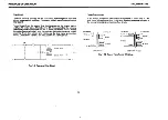
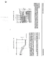
Page 114: ...EPSON PRINTERS y 31 FIGURE 5 1 5 3 FINAL ACTIONS ...

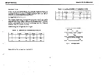
Page 115: ...FINAL ACTIONS EPSON PRINTERS 17 FIGURE 5 2 5 4 ...

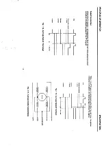
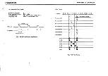
Page 116: ...EPSON PRINTERS V A FIGURE 5 3 5 5 FINAL ACTIONS ft 9 ...

Page 117: ...r shaft 5 5 Sprocket gear teeth 5 6 Ribbon Driving Gear shaft 5 3 Planetary Gear Leaf Spring 5 3 Planetary Lever subassembly shaft 5 3 Belt Driven Pulley flange and washer 5 3 Sliding part between release sub release levers 5 5 Paper Feeding Roller and stand 5 5 Felt Ring 168 5 5 5 6 EPSON PRINTERS TABLE 5 4 BONDING POINTS FX MX RX 100 PRINTERS REF NO PRODUCT DESCRIPTION FIGURE 31 Loctite Terminal...

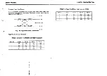
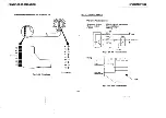
Page 118: ...EPSON PRINTERS 12 1 J t32 M iv FIGURE 5 4 5 7 FINAL ACTIONS A a ...

Page 119: ...FINAL ACTIONS FIGURE 5 5 5 8 EPSON PRINTERS 38 ...

Page 120: ......

Page 121: ...es of the printer removing all paper lint and dust with a brush or vacuum Clean the face of the Print Head with Film Remover to remove any ink that might be blocking the pin exit holes Clean the Ribbon Mask with Film Remover of any built up ink Clean the outer casing with a mild detergent such as Formula A Reinstall any parts which were removed for servicing Replace the Printer Cover and confirm p...

Page 122: ...tion Tractor Feed Adjustable Sprocket Friction w removable tractor Adjustable Sprocket Paper Fanfold Single Sheet Fanfold Single Sheet Fanfold Single Sheet Roll Paper Fanfold Single Sheet Fanfold Single Sheet Fanfold Single Sheet Fanfold Fanfold Single Sheet Fanfold Power Source 120 220 240 VAC 10 120 220 240 VAC 10 120 220 240 VAC 10 120 220 240 VAC 10 120 220 240 VAC 10 120 220 240 VAC 10 120 22...

Page 123: ...nditions of DIP Switch No 1 FX 85 185 286 sw Function OFF ON Factory Set Condition 1 1 Typafacs Pica Condensed OFF 1 2 ZERO font 0 0 OFF 1 3 Papcr snd daiscior Valid Invalid OFF 1 4 Input buffer FX 8 f 1004 User dafind Character User RAM area Character mode FX 8S 18S 105 IBM ESC P Wf 1 5 Print mode at POWER ON Normal Emphasized OFF 1 6 International character sat See Table 6 2 1 7 International ch...

Page 124: ...selected mode and no external software codes This setting affects pin 36 on the connector Some computers control this pin if they do control the pin the switch setting should always be off SW2 2 Isset to ON only when installing the optional cut sheet feeder SW2 3 FX85 FX 185 and FX286 in the ESC P mode This position is used to set the automatic skip over perforation function a When this switch is ...

Page 125: ...h hands as shown below Fig 6 1 Removal of SW Access Cover There are two DIP switches inside the printer The switches set to the upper position are ON to the lower position OFF Usea small pocket screwdriver to set switches to the On or OFF position fig 6 2 CAUTION Do Not use a pencil to change switch positions Lead from the pencil can short the switch internally 6 4 o EPSON PRINTERS 1 J 3 4 i j 3 4...

Page 126: ...o with slash SW1 3 This pin is used to activate or deactivate the paper end detector When this pin is turned ON the paper end detect function becomes invalid upon power application and the printer is allowed to operate evenifout of paper With the printerinthis state input off control code ESC9 will permit the paper end detector to be activated again 6 5 GENERAL SW1 4 Download characters can be def...

Page 127: ... refers to pin 36 on the connector Some computers control this pin if they do control the pin SW should be OFF SW2 2 IfON the buzzer will sound if OFF the buzzer will not sound at all SW2 3 This pin is used to set the automatic skip over perforation function i 6 6 EPSON PRINTERS SW2 4 Forces an automatic line feed with each carriage return When OFF line feed must be provided via software as needed...

Page 128: ...wires hooked to the Control Panel on the right fig 6 4 ScrowB Wirat Fig 6 4 Removal of Upper Case 1 6 Lift the edge of the upper case closest to you then remove the case by pulling upward m 6 7 Fig 6 5 Removal of Upper Case 2 The two DIP Switches are located inside the printer DQMr W SW2 Fig 6 6 Location of DIP Switches GENERAL ...

Page 129: ...r OFF position when using the printer SW1 2 Graphic symbols corresponding to control codes 128 through 159 are selected by setting this pin to the ON position SWl 3 This pin is used to enable or disable the buzzer When this pin is at the ON position the buzzer will not sound When this pin is at the OFF position the buzzer will sound Ifa mechanical error occurs the buzzer will sound regardless of t...

Page 130: ...s set to the OFF position the SLCT INsignal is not fixed internally thus permitting the printer to be controlled bya host computer This refers to pm No 36 on the connector Some computers control this pin if they do control the pin SWshould be OFF SW2 3 Forces an automatic line feed with each carriage return When OFF line feed must be provided via software as needed SW2 4 This pin is used to set th...

Page 131: ...sensor provided the external computer is selected via switch 1 8 2 Setting switch 1 8to OFF will permit the printer to be controlled bythe host computer t 1 I 6 10 EPSON PRINTERS TABLE 6 11 Character Size and Maximum Column Length CHARACTER SIZE PIN NUMBER MAXIMUM COLUMN SW1 3 SW1 4 LENGTH Standard OFF OFF 136 Condensed OFF ON 233 Emphasized ON ON 136 Selection of the enlarged printing mode in con...

Page 132: ...F OFF ON Italy OFF OFF OFF Spain After selecting the appropriate switch settings replace the plastic covers over the DIPSwitch pins 6 4 FX 85 185 286 JUMPERS Seven jumpers are provided on some FXMB FXMM boards TABLE 6 14 Functions of Jumper Wires GENERAL Jumper No Description Factory Set Condition J1 ON OFF Mask CPU Non mask CPU Always OFF J2 ON OFF 4KRAM 2KRAM OFF J3 ON OFF 4KflAM 2KRAM OFF J4 ON...

Page 133: ... 105 185 206 Optional circuit board for the FX 80 100 i s 1 1 CNS 1 1 CN3 1 18 pm ISptn 40p n z 38 pm 4 pin 1 D FXMB FXMM board u 8 pin 26 pin CNB 1 1 CN7 1 1 CN2 1 Power Tf Ant 4 former 3 7 2 P Stntoi 7 Iz Option Intsrfaca 2y Mo l r Comptiior AC Inpul 6 12 6 5 2 FX 80 FX 100 Cable Connections Host Compute V M 3560 3510 Printer Mechanism A T CN4 1 1 CNS 1 jOiJin IC Sochal J 18 pint 16 pina t 1 36 ...

Page 134: ... COMPOTER HOST COMPUTER 6 13 6 5 4 MX 80 MX 100 Cable Connections M 3360 3210 Printer Mechanism Conifol panel 7 9 leads CN6 13 pm male type CN2 B pin male type 21 Tianslormer Power lilter CN6 28 pin male type CN6 28 pm lemaie type Diivef ciicuil board I CN5 22 Pin CN4 22 pin male type 7 CN4 22 pin lemale type Coriitoi c ltuii board I CN3 26 pin I lemale type majej ge 7V CN5 22 pm lemale type CNt 3...

Page 135: ...at are larger than tne IC The proper orientation of the IC in the socket isshown by the following symbol fig 6 10 Fig 6 10 Offset Orientation of IC Symbol When replacing IC s be sure to order the proper IC for the printer being serviced 6 14 6 6 1 FX 85 185 286 IC Locations FXEXT Board C2 5 CNI 0 C3 U C5 4168 20 O 14 4I6B ZC 32 N 15 1 CI C4 it EPSON PRINTERS 25 5A 20N _ 15 l4 i e n C7 CB C9 u 20 a...

Page 136: ...ou Q F t SS8 UNIT Y4402I200003 FXMB FXMM Board I k 3A 38 4A 5A K 40l il l 48 258 i Amh l iO M s ti i 11 4B s 1 5o ji yd o f i w i iWi isV 1 t W Anui e ts 9 3 zl p M t 3 CNI 5 1 I T r I rr 1 mS as2 00 o6 s28 iS i5 jLji iii if CJi 5 r 14 1 4 t IQ vq to K Ht l l c 7 i K sf S Sio Lj 98 OHK c i6 m kwV jbUL c i I i Ii c40 m i n c n I I 2 3 4 S HAIJOOI OOIIO J GENERAL ...

Page 137: ...lO H lO T4LS374 74Lft7J C 0 74 S174 Cll 74l J74 0 J X CRI t ca c x a t 74i tiia 10 20 2C 3C 3C o IS 5A f4t 00 Q K z 2 u IS 2 3 I L CTTHiTiTj l UH V A tP wo jCH 5 SfiS UNIT Y44020500008 FMBOBOARD 6 16 101 CM 0 i i Hi i2 S o 8 i VC j y r IS ij tl J I sy EPSON PRINTERS It 4 l i i M CHI r V 14 ca Op CD ci 85 5 CD Sn I j 98 6 2 D CJ L U L i ii r T I6 C J ...

Page 138: ...OG A ll o H c c 1 s B a r 0i9 in t 020 Ci2 Ci Old c rv a A Q H30 O RXMC and RXMB boards are identical with the exception that on the RXMB board IC s5A and 6A have been replaced with one chip 6A Also chips 68 and 8B have been replaced with one chip 7B 74I S05 lALiOi 7 O o C J2 j HJ4 t rtJJ 0 C I9V1 6 17 A i s I I tf v o_ ku AAsf Q2S e 027 0 26 A 3 H 6 Qj A64 tt A 4 It M GENERAL ...

Page 139: ...GENERAL 6 6 4 MX 80 MX 100 IC Locations t Ik HMTP BOARD UNIT G49020t000 2 EPSON PRINTERS 3 5 Q SiYjfs 3 6 18 ...

Page 140: ...III X X FX 100 X X X X FX 80 X X X X FX 80 FA III X X X X RX 80 X X X RX 100 X X X FX 85 185 286 X X X X FX 80 X X o X X FX 100 X X X X 6 19 GENERAL TABLE 6 16 Epson Interface Board Capabilities XEROX PART NO EPSON PART NO BOARD CAPABILITIES 140N458 8161 IEEE 488 INTERFACE BOARD 140N485 8145 RS 232 CURRENT LOOP 2K BUFFER 75 9600 BPS 140N460 8148 RS 232 CURRENT LOOP 2K BUFFER XON XOFF 75 9600 BPS 1...

Page 141: ... Switches On Board 8161 There are two DIP switches on the Interface Board The settings of these switches are contained in Fig 6 11 Table 6 17 DIPSwitch 1 is used to assign the printer device number The ON position of each pin corresponds to binary 1 the OFF position to binary 0 Example of setting the printer number 6 isshown in Fig 6 11 DIP SW 2 ON OFF 1 1 1 1 1 1 1 1 1 1 1 1 DIP SW 1 6 5 4 3 2 1 ...

Page 142: ... 2 Positive Note 1 OFF 1 5 ON 1 6 Bit Rate Selection See Table 6 19 OFF 1 7 ON 1 8 OFF Note 1 Positive Data Entry Enabled Reverse Channel ON 3 to 27V Data Entry Disabled Reverse Channel OFF 3Vto 27 2 Negative Data Entry Enabled Reverse Channel OFF 3 to 27V Data Entry Disabled Reverse Channel ON 3Vto 27V 6 21 GENERAL Table 6 19 Bit Rate Selection Bit rate SW1 5 SW1 6 SW1 7 SW1 8 75 ON ON ON ON 100 ...

Page 143: ...hen the vacantarea reachesthe above value 6 22 EPSON PRINTERS Table 6 22 Setting of Jumpers Jumper Function Factory Setting J1 ON Pull up TTY TXD to 12 via 470 ohm resistor See Note 1 OFF J2 ON Connect TTY RXD Return to signal ground See Note 1 OFF J3 ON Connect TTY TXD Return to signal ground See Note 1 OFF J4 ON Pullup TTY RXD to 12Vvia470 ohm resistor See Note 1 OFF J5 ON Pullup DSR to 12V ON J...

Page 144: ...ON OFF ON OFF ON OFF ON OFF JCL OFF ON OFF ON OFF ON OFF ON RS 232C level Current Loop XON XOFF control 0 X X X 0 X X X Flag Control 0 X 0 X 0 X 0 X XON XOFF control X 0 X 0 X X X X Flag Control X X X X X 0 X 0 O Protocol possible X Protocol impossible 6 23 GENERAL 6 8 3 Setting The Switches And Jumpers On Board 8145 Interface board 8145 contains two DIP switches and 7 jumpers to permit selection ...

Page 145: ...1 5 1 6 152 ON ON 288 OFF ON 580 ON OFF 1936 OFF OFF Note Whenever the above switches are changed be sure power isoff Table 6 27 Setting of DIPSwitch 2 Switch Function Fartory 2 1 OK1 7 bit word length OFF 8 bit word length ON 2 2 ON In the state that serial data entry is disabled Reverse Channel OFF In the state that serial data entry is disabled Reverse Channel SPACE RS 232C ON 2 3 OFF MARK RS 2...

Page 146: ...op level at the same time otherwise the printer will be damaged 6 25 GENERAL 6 8 4 Setting The Switches And Jumpers On Board 8149 Interface board 8149 contains two DIP switches and 13 jumpers to permit selection of various conditions The factory set and function of each switch and jumper are shown in Tables 6 29 through 6 33 Table 6 29 Setting of DIPSwitch 1 Switch Function ON OFF Factory Set 1 1 ...

Page 147: ...2 3 ODD EVEN parity selection Even Odd OFF 2 4 Not Used OFF 2 5 ON 2 6 Bit Rate Selection See Table 6 32 OFF 2 7 ON 2 8 OFF 6 26 EPSON PRINTERS Table 6 32 Bit Rate Selection Bit Rate 2 5 2 6 2 7 2 8 75 ON ON ON ON 110 ON ON ON OFF 134 5 ON ON OFF ON 150 ON ON OFF OFF 200 ON OFF ON ON 300 ON OFF ON OFF 600 ON OFF OFF ON 1200 ON OFF OFF OFF 1800 OFF ON ON ON 2400 OFF ON ON OFF 4800 OFF ON OFF ON 960...

Page 148: ... mode see note 4 OFF JRS ON Receive data in RS 232C mode see note 4 ON JNOR ON Flag polarity selection Positive see note 5 6 ON JREV ON Flag polarity selection Negative see note 5 7 OFF 6 27 GENERAL Note 1 If the host computer is not equipped with the power supply for the Current Loop interface these Jumpers must be connected to perform communication via the Current Loop mode 2 When either DSR or ...

Page 149: ...rr Si rrV i t jr f 1 t ...

Page 150: ...he bottom of the page identifies it as a revised page The actual change is identified as follows Text Black Vertical Bar in Margin Tables Black Vertical Bar Left of Changed Date Illustrations Small BlackSquare Below Illustration If the same page is changed by a later revision the first marks are removed and new ones are added to identify only the new information When the entire manual is re issued...

Reviews: