Setup & Operation 3. Environments and Installation
36
G3 Rev.14
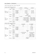
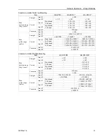
3.3.1 Table Top Mounting – Straight Arm
Center of Joint#3
Maximum space
Motion range
Area limited by mechanical stop
Base mounting face
a
b
c
d
e
f
g
h
j
k
q
m
n
p
G3-251S
140°
2°
141° 2.3°
79.3
84.0
120 250 221.9 224.5 143.3°
150
9.6
6.7
G3-251C
137° 6.3°
92.0
120
4.1
10.7
G3-301S
142° 3.8°
96.2
104.8
170
300
260.2 263.9
145.8°
150
9.6
6.7
G3-301C
141° 4.8°
107.1
120
4.1
10.7
G3-351S
142° 3.8°
134.2
142.3
220
350
298.5 303.3
150
9.6
6.7
G3-351C
142° 3.8°
146.6
120
4.1
10.7
g
Length of Arm #1 (mm)
b
Joint #1 angle to hit mechanical stop (degree)
h-g Length of Arm #2 (mm)
d
Joint #2 angle to hit mechanical stop (degree)
m Stroke of Joint #3 (mm)
n
Joint #3 range to hit lower mechanical stop (mm)
f
Motion range
p
Joint #3 range to hit upper mechanical stop (mm)
a
Motion range of Joint #1 (degree)
j
Range from center of axis to back end (mm)
c
Motion range of Joint #2 (degree)
k
Range from center of axis to back end after moved to
mechanical stop (mm)
e
Mechanical stop area
q
Joint #2 motion range + angle to hit mechanical stop (degree)
Summary of Contents for G3 Series
Page 1: ...Rev 14 EM183R3623F SCARA ROBOT G3 series MANIPULATOR MANUAL ...
Page 2: ...MANIPULATOR MANUAL G3 series Rev 14 ...
Page 8: ...vi G3 Rev 14 ...
Page 14: ......
Page 84: ...Setup Operation 5 Motion Range 72 G3 Rev 14 ...
Page 86: ...74 ...
Page 200: ...Maintenance 15 Maintenance Parts List 188 G3 Rev 14 ...


