Setup & Operation 5. Motion Range
G3 Rev.14
71
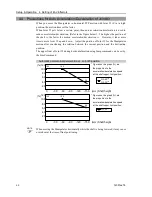
5.3 Setting the Cartesian (Rectangular) Range in the XY
Coordinate System of the Manipulator (for Joints #1 and #2)
Use this method to set the upper and lower limits of the X and Y coordinates.
This setting is only enforced by software. Therefore, it does not change the physical
range. The maximum physical range is based on the position of the mechanical stops.
EPSON
RC+
Set the XYLim setting on the [XYZ Limits] panel shown by selecting [Tools]-[Robot
Manager].
(You may also execute the XYLim command from the [Command Window].)
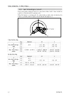
5.4 Standard Motion Range
The following “motion range” diagrams show the standard (maximum) specification.
When each Joint motor is under servo control, the center of Joint #3’s (shaft’s) lowest
point moves in the areas shown in the figure.
“Area limited by mechanical stop” is the area where the center of Joint #3’s lowest point
can be moved when each joint motor is not under servo control.
“Mechanical stop” sets the limited motion range so that the center of Joint #3 cannot move
beyond the area mechanically.
“Maximum space” is the area that contains the farthest reach of the arms. If the
maximum radius of the end effector is over 60 mm, add the “Area limited by mechanical
stop” and “radius of the end effector”. The total value is specified as the maximum area.
For the motion area figures, refer to
Setup & Operation 3.3 Mounting Dimensions
.
Summary of Contents for G3 Series
Page 1: ...Rev 14 EM183R3623F SCARA ROBOT G3 series MANIPULATOR MANUAL ...
Page 2: ...MANIPULATOR MANUAL G3 series Rev 14 ...
Page 8: ...vi G3 Rev 14 ...
Page 14: ......
Page 84: ...Setup Operation 5 Motion Range 72 G3 Rev 14 ...
Page 86: ...74 ...
Page 200: ...Maintenance 15 Maintenance Parts List 188 G3 Rev 14 ...


