Maintenance 6. Arm #2
134
G6 Rev.21
Joint #2 motor
Installation
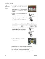
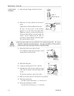
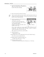
(1) Mount the motor flange on the Joint #2 motor.
4-M5
×
15
+
M5 small washer
(2) Mount the waveform generator on the Joint #2
motor.
Apply grease without touching the motor axis.
Be sure to fit the end face of the waveform
generator to the end face of the motor shaft.
Tighten one of the set screws on the flat face of
the motor shaft until the screw just touches the
surface. Insert a bushing into the other set
screw hole to prevent damage to the motor shaft.
Then, tighten both set screws.
2-M4
×
8
set screw
M4 bushing
Waveform
generator
SK-1A
grease (6g)
CAUTION
■
See the figures above for the orientation of the waveform generator. Be sure to
install the waveform generator properly. Improper installation of the waveform
generator will result in improper function of the Manipulator.
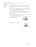
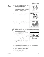
(3) Mount the Joint #2 motor unit on Arm #2.
If it is difficult to mount the motor, push it while
moving Arm #2 slowly by hand.
4-M4
×
15
(4) Mount the spring plate.
2-M4
×
10
Spring plate
(5) Connect the connectors X221, X21, and X62.
(6) Re-bundle the cables in their original positions
with a wire tie removed in the removal procedure
step (6).
Do not allow unnecessary strain on the cables.
(7) Make sure that the connectors X22 and X33 are connected.
(8) Mount the arm top cover.
For details, refer to
Maintenance: 3.1 Arm Top Cover
.
(9) Perform the calibration of Joint #2.
For details refer to
Maintenance: 13. Calibration.
Summary of Contents for G6 series
Page 1: ...Rev 21 EM183R3621F SCARA ROBOT G6 series MANIPULATOR MANUAL ...
Page 2: ...MANIPULATOR MANUAL G6 series Rev 21 ...
Page 8: ...vi G6 Rev 21 ...
Page 14: ......
Page 94: ......
Page 216: ...Maintenance 14 Maintenance Parts List 204 G6 Rev 21 ...


