A3 Size Color Flat Bed Scanner GT-30000
Revision A
OPERATING PRINCIPLES
General Description
23
2.1 General Description
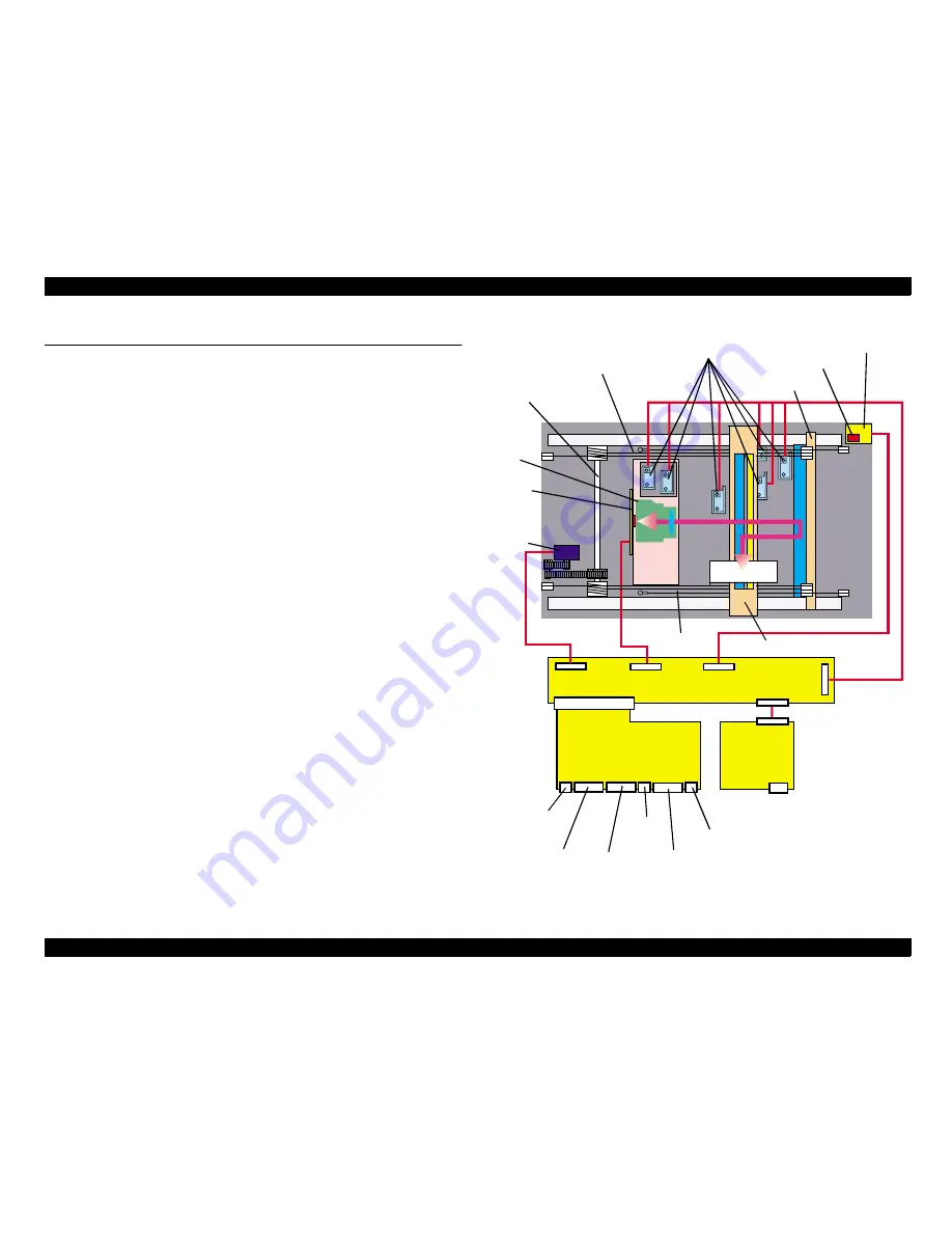
The EPSON GT-30000 are mainly composed of following units:
"
Scanner mechanism
(Lamp and mirror mechanism and drive unit, lens-CCD sensor unit drive
mechanism, Document size sensors)
"
Control circuit boards
"
Power supply circuit boards
"
ADF (Refer to A3 Auto Document Feeders service manual for detail)
The EPSON A3 flat-bed type scanners usually read images by moving the
integral CR unit which consists of the lamp, mirror, and lens-CCD sensor. This
scanner, however, characteristically has the CCD sensor and the lens in the
whole unit attached onto the mechanism as an independent unit. This scanner
is also equipped with the newly designed focusing function which enables the
scanner to focus by adjusting the distance between the lens and the CCD
sensor. Since the separate units in the mechanism such as the lamp and the
mirrors move at their own speed for reading, the incident distance of the
reflected light from the document to the CCD sensor is kept constant.
The control circuit board is designed to be inserted from the rear of the
scanner, and the power supply board fits into a separate shielded
compartment, with both circuit boards being connected only by the relay circuit
board connector inside the scanner mechanism. This makes removal and
maintenance operations much easier.
Figure 2-1. Main Mechanism Structure of GT-30000
HP sensor
PBA-PANEL
board
Document
CR
Motor
unit
lens unit
CN3
CN7
PBA-CONNECT board
CN6
CN5
CN9,
CN10
Drive
shaft
Document size sensors
Drive wires
Drive wires
AC in
ADF I/F
SCSI
terminator SW
SCSI
W/N SW
SCSI
ID SW
Normal
SCSI I/F
CN13
PBA-MAIN board
PWS-
POWER
board
PBA-INS
board
(CCD)
Mirror unit
Lamp/mirror unit
Wide
SCSI I/F
CN2
Summary of Contents for GT-30000 Series
Page 9: ...C H A P T E R 1 PRODUCTOUTLINE ...
Page 22: ...C H A P T E R 2 OPERATINGPRINCIPLES ...
Page 29: ...C H A P T E R 3 TROUBLESHOOTING ...
Page 37: ...C H A P T E R 4 DISASSEMBLY ASSEMBLY ...
Page 55: ...C H A P T E R 5 ADJUSTMENTS ...
Page 65: ...C H A P T E R 6 MAINTENANCE ...
Page 67: ...C H A P T E R 7 APPENDIX ...
Page 82: ...Model ES 9000H GT 30000 Board PBA MAIN Rev 1 Sheet 1 3 ...
Page 83: ...Model ES 9000H GT 30000 Board PBA MAIN Rev 1 Sheet 2 3 ...
Page 84: ...Model ES 9000H GT 30000 Board PBA MAIN Rev 1 Sheet 3 3 ...
Page 85: ...Model ES 9000H GT 30000 Board PWS POWER Rev A Sheet 1 1 ...
Page 86: ...Model ES 9000H GT 30000 Board PBA Connect Rev 1 Sheet 1 1 ...


