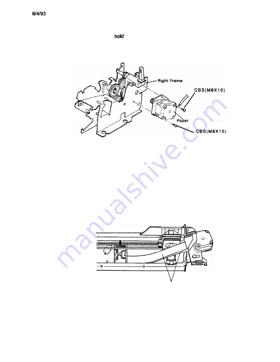
3.2.5.2 Removing the Paper Advance Motor
1.
Remove the printer mechanism from the lower case, as described in Section 3.2.4.
2.
Remove the 2 CBS (M8 X 10) that
the paper feed motor the right frame.
3.
Remove the paper
advance
motor from the right frame.
Advance Motor
Figure 3-14. Removing the Paper Advance Motor
Assembly Note
See Section 3.2.5.13 for details on arranging and positioning the motor cable.
3.2.5.3 Removing the Flexible Flat Cable (FFC)
1.
Remove the printhead, as described in Section 3.2.1.
2.
Remove the printer mechanism from the lower case, as described in Section 3.2.4.
3.
Remove the FFC from the clips that hold it along the rear side of the printer mechanism. Make sure
that the FFC is free.
4.
Remove the FFC from clip A on the head cable holder at the rear of the printer mechanism.
5.
Remove the four clips that hold the head cable holder to the base frame. Remove the FFC and the
head cable holder.
FFC
Figure 3-15. Removing the FFC
Assembly Note
See Section
3.2.5.13
for details on arranging and positioning the FFC.
3-14
Summary of Contents for LQ-1170
Page 1: ...LQ 1170 24 PIN DOT MATRIX PRINTERS TM LQ8 1170 ...
Page 2: ...L Q 8 7 0 1 1 7 0 SERVICE MANUAL EPSON T Printed on recycled paper ...
Page 101: ...10 9 91 Yes NO Replace pluggable chips on main board 5 6 ...
Page 110: ...Table 5 4 Repair of the Power Supply Board Continued 5 15 ...
Page 118: ......
Page 121: ...REV A Figure 6 2 LQ 870 Lubrication Points 6 3 ...
Page 122: ...REV A Figure 6 3 LQ 1170 Lubrication Points 6 4 ...
Page 134: ...1 I II ...
Page 135: ...REV A Q m u D w IL 0 1 xl Figure A 3 CO60 DRV Board Circuit Diagram A 11 ...
Page 136: ...Figure A 4 CO60 PSB Board Circuit Diagram A 12 ...
Page 138: ...LO SLOE002 OWO9 1Nd 0 9 0 3 5 f l P I 11 I 01 I 6 I 8 1 L 9 I 9 I B I I2 I 2 I 1 ...
Page 142: ...REV A Fl 24ov T3 IsA I I II II AL I CU rl Figure A 10 C060 PSE Board Component Layout A 1 8 ...
Page 143: ...LMS d10 IP IMS dla ...
Page 144: ...REV A A 4 EXPLODED DIAGRAM Figure A l 2 1 Exploded Diagram for LQ 870 A 2 0 ...
Page 145: ......
Page 146: ...REV A Figure A 13 1 Exploded Diagram for Model 5DlO A 22 ...
Page 147: ... 5 2 5 610 c 3 5 9 0 El ...
Page 149: ...REV A A 5 CASE OUTLINE DRAWING Figure A l 4 1 Case Outline Drawing for LQ 870 A 25 ...
Page 151: ...lllllll IllI l l IIIIII II0 IIll III1 I I I C O 6 1 M A I N B o a r d A 3 7 ...
Page 152: ... U nRonenl2 i i C O 6 0 HAIN B t _1 m r OL J IIA IS I 19 CNI 36 I I8 I 23 IS ...
Page 153: ...a i iJ 0 E fig tfti I z ...


