


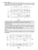


Exclusive registers
1) Program counter (PC)
The program counter holds 16 memory address bits for the instruction being currently executed. The
CPU fetches the instruction from the memory address indicated by the program counter. This counter
is automatically incremented when its own contents are transmitted to the address bus. In program
jump, the increment does not work and a new value is set directly to the counter.
2) Stack pointer (SP)
The stack pointer holds 16, high-order address bits in the stack of an external RAM. An external stack
is formed of a LIFO (last-in, first-out) file.
The data is transferred from the designated register in the CPU to the stack or vice versa on command
PUSH or POP.
When the data are taken out (POP) of the stack, the data which has been entered (PUSH) last is re-
moved first. The stack is useful to facilitate multilevel interruption, limitless subroutine nesting or a
variety of data processings.
3) Index registers (IX and IY)
Two independent index registers (IX and IY) hold 16-bit reference address for index mode addressing.
In this index mode, an index register is used for the reference address for designating the memory
area where data is put in or out. In the index addressing command, the addition of 1 byte displace-
ment to the contents of this register indicates an effective address. This displacement is given as an
integer with two-complement code.
This addressing mode is widely used in different programs, especially those for which data table is re-
ferred to.
4) Interrupt page address register (1)
The Z-80 CPU has a mode in which indirect call (indirect subroutine jump) can be applied to any
memory location according to the interruption.
For this purpose, register I is provided. The contents of this register refer to the 8 high-order indirect
address bits. The address which meets the equipment which has applied an interruption is assigned
to the 8 low-order bits. In this system, the interruption handling routine can be located at any area of
the memory dynamically, thus enabling jumping to this routine in a very short access time.
5) Memory refresh register(R)
The Z-80A CPU has a built-in memory refresh counter. Therefore, a dynamic memory can be easily
used like a static memory.
This 7-bit register is automatically incremented whenever the instruction is fetched.
The data in this register decodes the instruction fetched by the CPU and is put on the low-order bits
of the address bus in synchronism with the refresh control signal while this instruction is executed.
In this refresh mode, the programmer need not take care and the CPU operation has no delay. These
are the features of the refresh mode. Data can be loaded in this register (register R) according to the
program for testing. However, normally, this should not be used for testing.
During refresh, the contents (data) in register I are output to the high-order 8 bits of the address bus.
Accumulators and flag registers
The CPU has 2 sets of independent, 8-bit, accumulators and, in combination with these, 2 sets of 8-bit
flag registers. An accumulator holds the 8-bit result of arithmetic or logical operation. On the other
hand, a flag register sets the status of 8-bit or 16-bit operation result, e.g. whether or not the result is
equal to zero.
7-3
Summary of Contents for LQ-1500
Page 1: ...L Q 1 5 0 0 SERVICE MANUAL EPSON a9Printed on Recycled Paper ...
Page 8: ...Table 1 1 3 ...
Page 16: ...Note Direction refers to the direction of signal as viewed from the UXMCL circuit board ...
Page 18: ...2 6 ...
Page 21: ...Note Direction refers to the direction of signal as viewed from the UXDRV circuit board 2 9 ...
Page 39: ...Fig 2 26 CR motor drive circuit 2 2 7 ...
Page 42: ...Table 2 17 Data of decelerate time ...
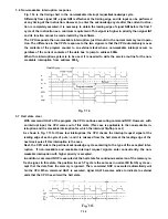
Page 43: ...Fig 2 29 Deceleration and stop at home position In case of 1163 769 pps ...
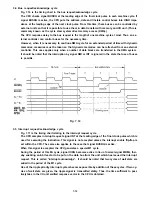
Page 48: ...Fig 2 35 Paper feed timing chart In case of N pulse paper feed N 5 ...
Page 56: ...3 Correspondence between dot wires and FPC terminals Fig 2 45 Printhead connector 2 4 4 ...
Page 64: ...3 3 ...
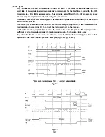
Page 66: ...3 1 3 3 Handshaking of the parallel interface Fig 3 1 Parallel interface timing 3 5 ...
Page 68: ...3 1 5 Circuit diagram 3 7 ...
Page 69: ...Fig 3 4 Component layout of IUPIF board ...
Page 73: ...D DIP 4 Table 3 10 Setting of DIP 4 3 12 ...
Page 80: ...3 2 4 Block diagram 3 19 ...
Page 81: ...3 2 5 Circuit diagram IURS CIRCUIT BOARD UNIT NO Y49520300000 Fig 3 9 IURS circuit board 3 20 ...
Page 82: ...Fig 3 10 Component layout of IURS board ...
Page 90: ...3 3 5 Block diagram m x 6 IA 3 29 ...
Page 93: ...Fig 3 17 Component layout of IUIE ...
Page 115: ...3 54 ...
Page 116: ...3 55 ...
Page 117: ... Fault of selection and feed 3 56 ...
Page 118: ... Fault of paper guides1 3 57 ...
Page 119: ... Fault of output selector 3 58 ...
Page 120: ... Other faults Paper is fed at an angle 3 59 ...
Page 123: ......
Page 144: ... Mechanical components Model 3660 Y450590100 Maintenance tool 5 3 ...
Page 145: ...5 2 Check out Procedure Repair by Unit Replacement 5 4 ...
Page 146: ...5 5 ...
Page 147: ...5 6 ...
Page 148: ...5 7 ...
Page 149: ... Carriage does not return to home position when power switch is turned on 5 8 ...
Page 150: ... Carriage does not move ...
Page 151: ...5 10 ...
Page 152: ... Control panel indication is faulty Paper feeding motor does not stop 5 11 ...
Page 153: ... Switch on control panel can operate in the on line state 5 12 ...
Page 154: ... Sheet loading does not work properly ...
Page 156: ... Carriage does not move in Self Printing Test 2 5 15 ...
Page 157: ... Paper feeding is not made in Self Printing Test Printing is faulty 5 16 ...
Page 158: ... Operation is abnormal when connected with host computer 5 17 ...
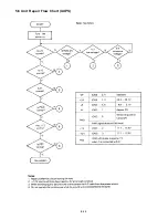
Page 159: ...5 3 Unit Repair Flow Chart UXMCL 5 18 ...
Page 160: ...1 Printing Troubles 5 19 ...
Page 161: ...5 20 ...
Page 162: ... ...
Page 163: ...5 22 ...
Page 164: ...5 23 ...
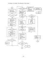
Page 165: ...2 Carriage Troubles 5 24 ...
Page 166: ...5 25 ...
Page 167: ...5 26 ...
Page 168: ...5 27 ...
Page 169: ...5 28 ...
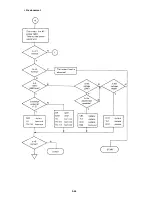
Page 170: ...3 Paper Feeding Troubles 5 29 ...
Page 171: ...5 30 ...
Page 172: ...5 31 ...
Page 173: ...4 Sheet Loading Problem 5 32 ...
Page 174: ...5 4 Unit Repair Flow Chat t UXDRV 5 33 ...
Page 175: ...1 Printing Troubles 5 34 ...
Page 176: ...5 35 ...
Page 177: ...2 Carriage Troubles 5 36 ...
Page 178: ...3 Paper Feeding Troubles 5 37 ...
Page 179: ...5 38 ...
Page 180: ...4 Sheet Loading Troubles 5 39 ...
Page 181: ...5 5 Unit Repair Flow Chart IUPIF 5 40 ...
Page 182: ...5 41 ...
Page 183: ...5 6 Unit Repair Flow Chart UXPS 5 4 2 ...
Page 184: ... 24 voltage is not output The malfunction of the primary 5 43 ...
Page 186: ...The voltage of 24 is low Excessive voltage is output 5 45 ...
Page 187: ... 5 is abnormal 5 46 ...
Page 188: ...Vx is abnormal 12 is abnormal 5 47 ...
Page 195: ...List of Principal lC s Table 7 1 7 1 ...
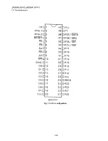
Page 209: ...Fig 7 16 Pin configuration 7 15 ...
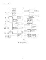
Page 210: ... 2 Block Diagram 8042 Fig 7 17 Block diagram 7 16 ...
Page 216: ......
Page 229: ...EXPLODED DIAGRAM FOR LQ 1500 12OV VERSION 7 35 ...
Page 230: ......
Page 231: ...7 37 ...
Page 232: ...7 38 ...
Page 233: ......
Page 234: ......
Page 235: ......
Page 236: ......
Page 237: ...UXPS CIRCUIT BOARD UNIT NO Y45020300000 7 43 ...
Page 238: ......
Page 239: ......
Page 240: ......
Page 241: ......


