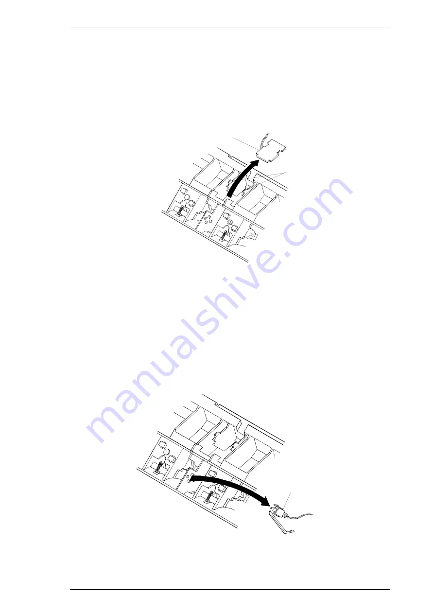
3.2.10.8 Removing the Rear PE Sensor Assembly
1
Remove the rear/front edge guide assembly, front cover, paper eject assembly, rear/front tractor
unit, and printer cover.
2.
Remove the panel board (see Section 3.2.2) and upper housing assemblies (see Section 3.2.7).
3.
Remove the printer mechanism (see Section 3.2.10).
4.
Turn the printer mechanism over, and insert a standard screwdriver or other prying tool into
hole in the rear frame shown in the figure.
5.
Release 2 clips while pushing up the rear PE sensor with the screwdriver or other prying tool.
6.
Remove the rear PE sensor after disconnecting the connector.
3.2.10.9 Removing the Front PE Sensor Assembly
1.
Remove the rear/front edge guide assembly, front cover, paper eject assembly, rear/front tractor
unit, and printer cover.
2.
Remove the panel board (see Section 3.2.2) and upper housing assemblies (see Section 3.2.7).
3.
Remove the printer mechanism (see Section 3.2.10).
4.
Turn the printer mechanism over on the reverse side and remove the front PE sensor by pushing
and releasing the 2 clips.
Rear PE Sensor Assembly
2 Clips
Figure 3-34 Removing the Rear PE Sensor Assembly
Front PE Sensor Assembly
Figure 3-35 Removing the Front PE Sensor Assembly
LQ-2170 Service Manual
Disassembly and Assembly
Rev.A
3-23
Summary of Contents for LQ-2170
Page 1: ...EPSON TERMINAL PRINTER LQ 2170 SERVICE MANUAL EPSON 4005735 ...
Page 5: ...REVISION SHEET Revision Issued Date Revision Page Rev A December 5 1995 1st issued ...
Page 11: ...Figure 1 1 Exterior View of the LQ 2170 Product Description LQ 2170 Service Manual 1 2 Rev A ...
Page 80: ......
Page 127: ...1 Abnormal CR Operation LQ 2170 Service Manual Troubleshooting Rev A 5 5 ...
Page 141: ...LQ 2170 Service Manual Troubleshooting Rev A 5 19 ...
Page 156: ...Appendix LQ 2170 Service Manual A 10 Rev A ...
Page 158: ...Appendix LQ 2170 Service Manual A 12 Rev A ...
Page 159: ...Figure A 3 C165 PSB Board Assembly Circuit Diagram LQ 2170 Service Manual Appendix Rev A A 13 ...
Page 160: ...Appendix LQ 2170 Service Manual A 14 Rev A ...
Page 161: ...Figure A 4 C165 PSE Board Assembly Circuit Diagram LQ 2170 Service Manual Appendix Rev A A 15 ...
Page 162: ...Appendix LQ 2170 Service Manual A 16 Rev A ...
Page 167: ...Figure A 9 LQ 2170 Exploded Diagrams 2 LQ 2170 Service Manual Appendix Rev A A 21 ...
Page 168: ...Figure A 10 LQ 2170 Exploded Diagrams 3 Appendix LQ 2170 Service Manual A 22 Rev A ...
Page 169: ...Figure A 11 C S F Bin1 Exploded Diagrams 1 LQ 2170 Service Manual Appendix Rev A A 23 ...
Page 170: ...Figure A 12 C S F Bin1 Exploded Diagrams 2 Appendix LQ 2170 Service Manual A 24 Rev A ...
Page 171: ...Figure A 13 C S F Bin2 Exploded Diagrams LQ 2170 Service Manual Appendix Rev A A 25 ...
Page 172: ...Table A 15 Part No Reference Table Appendix LQ 2170 Service Manual A 26 Rev A ...
Page 173: ...Table A 15 Part No Reerence Table Continue LQ 2170 Service Manual Appendix Rev A A 27 ...
Page 174: ...Appendix LQ 2170 Service Manual A 28 Rev A ...
Page 175: ...EPSON Printed in Japan 95 12 05 S ...


