Service Manual
Operating
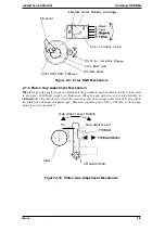
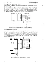
2.3.13 Color Ribbon Sensor Circuit
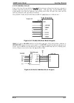
The printer’s color ribbon circuitry is shown in the figure below. The CPU receives signals (HIGH
or LOW) from the mechanical switch. The signal is HIGH (ON) when a color ribbon is installed
and is LOW (OFF) otherwise.
CPU (Cl)
P31
Printer
+5
Color
Ribbon
Sensor
51
I
I
Figure 2-25. Color Ribbon
2.3.14 Platen Gap
Sensor Circuit
Color Upgrade Kit
Sensor Circuit Diagram
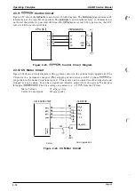
This printer has a connector switch to sense the
Gap) adjust lever position. The CPU
receives a signal from the
sensor and recognizes the
adjust lever position. The comector
switch is
when the printer is in copy
adjust lever position:2-6) and is
when the printer is in normal
adjust lever position:-l-+l). The printing speed
decrease in copy mode.
CPU (ICI)
P54
1
Figure 2-26. Platen Gap
Sensor Circuit Diagram
2-19
Summary of Contents for LQ-300 - Impact Printer
Page 1: ...EPSON TERMINAL PRINTER LQ 300 SERVICE MANUAL EPSON ...
Page 5: ...REVISION SHEET Revision Issue Date Revision Page Rev A September 28 1994 1st issue f v 1 ...
Page 34: ...c f ...
Page 101: ...Maintenance LQ 300 Service Manual Figure 6 1 LQ 300 Lubrication Points 6 2 Rev A ...
Page 110: ... Figure A 6 C130 PSB PSE Component Layout ...
Page 112: ...Appendix LC MMS vbeMantd Q ix iyii t v Figure A 8 LQ 300 Exploded Diagram 2 A 12 Rev A ...
Page 119: ... f ...


