background image

EPSON


LQ-570e/LQ-580

24


Pin


Impact


Dot


Printer

SEDM996002

®

SERVICE MANUAL

SERVICE MANUAL

SERVICE MANUAL

SERVICE MANUAL

Summary of Contents for LQ-570e

Page 1: ...EPSONLQ 570e LQ 580 24 Pin Impact Dot Printer SEDM996002 SERVICE MANUAL SERVICE MANUAL SERVICE MANUAL SERVICE MANUAL ...

Page 2: ...bject to change without notice o All effort have been made to ensure the accuracy of the contents of this manual However should any errors be detected SEIKO EPSON would greatly appreciate being informed of them o The above not withstanding SEIKO EPSON CORPORATION can assume no responsibility for any errors in this manual or the consequences thereof EPSON is a registered trademark of SEIKO EPSON CO...

Page 3: ... NOT CONNECT THE UNIT TO A POWER SOURCE UNTIL INSTRUCTED TO DO SO WHEN THE POWER SUPPLY CABLE MUST BE CONNECTED USE EXTREME CAUTION IN WORKING ON POWER SUPPLY AND OTHER ELECTRONIC COMPONENTS WARNING 1 REPAIRS ON EPSON PRODUCT SHOULD BE PERFORMED ONLY BY AN EPSON CERTIFIED REPAIR TECHNICIAN 2 MAKE CERTAIN THAT THE SOURCE VOLTAGES IS THE SAME AS THE RATED VOLTAGE LISTED ON THE SERIAL NUMBER RATING P...

Page 4: ...ved lubricants and adhesives required for servicing the product APPENDIX Provides the following additional information for reference Connector pin assignments Electric circuit boards components layout Exploded diagram Electrical circuit boards schematics Symbols Used in This Manual Various symbols are used throughout this manual either to provide additional information on a specific topic or to wa...

Page 5: ...cription Rev A February 10 2000 First Release Rev B February 17 2000 Component Layout added Adjustment Program version up Rev C March 30 2000 Revision 1 Chapter 3 Voltage waveforms have been added 2 Chapter 6 Illustrations have been corrected ...

Page 6: ...pe B Interface communication specification 29 1 5 Operation 31 1 5 1 Control Panel 31 1 5 1 1 Switches 31 1 5 1 2 LED 33 1 5 1 3 Buzzer 33 1 5 2 Functions 34 1 5 2 1 Usual Operation 34 1 5 2 2 Operation at Power on 34 1 5 2 3 Default Setting 35 1 5 3 Bi d Adjustment 36 1 5 4 EEPROM Initialization Method 36 1 5 5 Initialization 36 1 5 6 Errors 37 1 6 Control codes 38 1 6 1 ESC P2 38 1 6 2 IBM 2390 ...

Page 7: ...ousing Assembly Removal 79 4 2 5 C293 MAIN Board Removal 80 4 2 6 C293 PSB PSE Board Removal 82 4 2 7 Printer Mechanism Removal 83 4 2 8 Platen Removal 84 4 2 9 Printer Mechanism Disassembly 85 4 2 9 1 CR Motor Removal 85 4 2 9 2 PF Motor Removal 85 4 2 9 3 PF Gear Train Disassembly 86 4 2 9 4 PG Platen Gap Detector Removal 87 4 2 9 5 Release Detector Removal 87 4 2 9 6 Front PE Paper End Detector...

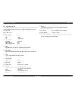
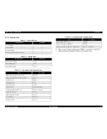
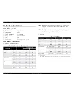
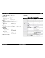
Page 8: ...C H A P T E R 1 PRODUCT DESCRIPTION ...

Page 9: ...lti part paper Envelop Card Label and Roll Paper o Fonts 9LQ 1 Draft Bitmap and 4 Scalable typefaces 8 Barcode fonts o Character tables Standard version 13 tables NLSP version 39 tables o Input buffer 64 Kbytes o Acoustic noise 49 dB A ISO 7779 pattern o Reliability Mean print value between failure MVBF MTBF 25 duty circle 19 million lines except print head MTBF 10000 POH Print head life 200 milli...

Page 10: ...der bin 1 C80638 Single bin cut sheet feeder bin 1 or bin 2 C80637 Pull tractor unit C80020 Roll paper holder 8310 Front sheet guide C81423 Serial I F card C82305 C82306 32 KB intelligent serial I F card C82307 C82308 Local Talk I F card C82312 32KB IEEE 488 I F card C82313 Coax I F card C82314 Twinax I F card C82315 IEEE 1284 parallel I F card C82345 Ethernet I F card for 10Base T 2 C82362 Ethern...

Page 11: ...rinting again more slowly than before o Resolution o Control code ESC P2 and IBM 2390 Plus emulation Refer to 1 3 1 Control Codes and Fonts Table 1 4 Print Speed and Printable Columns Printing Mode Character Pitch Printable Columns Printing Speed cps Normal Copy High speed draft 10 cpi 80 400 266 Draft 10 cpi 80 300 200 12 cpi 96 360 240 15 cpi 120 450 300 Draft condensed 17 cpi 137 257 171 20 cpi...

Page 12: ...6 IPS inches second o Input Data Buffer 64 Kbyte o Release lever The release lever must be set according to the following table Table 1 6 Release Lever Setting Position Lever Position Paper path Feeder Paper Media Friction Manual insertion front Cut sheet Single sheet Multi part Card Manual insertion rear Cut sheet Single sheet Card Envelope CSF Bin 1 High capacity cut sheet feeder Cut sheet Singl...

Page 13: ... CSF Minimum Maximum Minimum Maximum Width inch mm 3 9 100 10 1 257 7 2 182 8 5 216 Length inch mm 3 9 100 14 3 364 10 1 257 14 356 Thickness inch mm 0 0025 0 065 0 0055 0 14 0 0025 0 07 0 0055 0 14 Weight g m2 lb 52 14 90 24 64 18 90 24 Quality Plain paper Recycled paper Not curled not folded not crumpled Plain paper Recycled paper Not curled not folded not crumpled Printing on recycled paper is ...

Page 14: ...y Plain paper Recycled paper not curled not folded not crumpled Jointing Line glue at the top or one side of form Front Entry Rear Entry Manual Insertion High Capacity CSF Single Bin CSF Minimum Maximum Envelop No 6 Width inch mm 6 5 165 Length inch mm 3 6 92 Envelop No 10 Width inch mm 9 5 241 Length inch mm 4 1 105 Front Entry Rear Entry Minimum Maximum Manual Insertion High Capacity CSF Single ...

Page 15: ...pler and let the copy sheet flat 6 Never use continuous multi part forms that are jointed with metal staples Front Entry Rear Entry Min Max Manual Insertion High Capacity CSF Single Bin CSF Min Max Min Max Width inch mm 3 9 100 7 9 200 3 9 100 7 9 200 3 9 100 5 8 148 Length inch mm 5 8 148 7 9 200 3 9 100 7 9 200 3 9 100 5 8 148 Thickness inch mm 0 0087 0 22 0 0087 0 22 0 0087 0 22 Weight g m2 lb ...

Page 16: ...e below Base sheet width inch mm 4 101 6 10 254 4 101 6 10 254 Base sheet length one page inch mm 4 101 6 22 558 8 4 101 6 22 558 8 Base sheet thickness inch mm 0 0028 0 07 0 0035 0 09 0 0028 0 07 0 0035 0 09 Total thickness inch mm 0 0063 0 16 0 0075 0 19 0 0063 0 16 0 0075 0 19 Label weight g m2 lb 64 17 64 17 Quality AVERY CONTINUOUS FORM LABELS AVERY MINI LINE LABELS or the same quality labels...

Page 17: ... maximum printable area 203 2 mm ex When PW 257 mm 27 mm or more suppose paper is set to the center When PW 209 2 mm 3 mm or more When PW 209 2 mm Depend on the maximum printable area 203 2 mm ex When PW 257 mm 27 mm or more suppose paper is set to the center RM Right Margin When PW 216 mm 3 mm or more When PW 209 2 mm Depend on the maximum printable area 203 2 mm ex When PW 257 mm 27 mm or more s...

Page 18: ... a b l e A r e a Table 1 16 Printable Area for Envelop and Card Single Sheet Multi Part PW Width Refer to 1 2 4 Paper Specifications Refer to 1 2 4 Paper Specifications PL Length Refer to 1 2 4 Paper Specifications Refer to 1 2 4 Paper Specifications LM Left Margin 3 mm or more 3 mm or more RM Right Margin 3 mm or more 3 mm or more TM Top Margin 4 2 mm or more 4 2 mm or more BM Bottom Margin 4 2 m...

Page 19: ...Paper PW Width Refer to 1 2 4 Paper Specifications PL Length Refer to 1 2 4 Paper Specifications LM Left Margin When PW 228 6 mm 13 mm or more When PW 209 2 mm Depend on the maximum printable area 203 2 mm ex When PW 241 mm 13 25mm When PW 254 mm 21 30mm RM Right Margin When PW 241 3 mm 13 mm or more When PW 209 2 mm Depend on the maximum printable area 203 2 mm ex When PW 241 mm 13 25mm When PW 2...

Page 20: ... n Power consumption Approximately 36 W ISO IEC10561 Letter pattern Energy Star Compliant n Insulation resistance 10MΩ min between AC line and chassis DC 500V n Dielectric strength AC 1000 Vrms 1 min or AC 1200 Vrms 1 sec between AC line and chassis o 230 V version n Rated voltage range AC 220 to 240 V n Input voltage range AC 198 to 264 V n Rated frequency range 50 to 60 Hz n Input frequency rang...

Page 21: ... non operating 3 1 without condensation 2 during printing on multi part paper envelop card or label 3 without shipment container 1 2 9 Reliability o MVBF 19 million lines except printhead o MTBF 10000 POH o Printhead life 200 million strokes wire Mean print volume between failure 1 2 10 Safety Approvals o 120 V version n Safety standards UL1950 CSA C22 2 No 950 n EMI FCC part15 subpart B class B C...

Page 22: ...7 5 kg n Appearance See below o Physical Specifications including CSF bin1 High capacity bin CSF n Dimensions 415x433x366 mm WxDxH n Mass Approx 9 0 kg o Physical Specifications including CSF bin 1 Single bin CSF n Dimensions 415x443x385 mm WxDxH n Mass Approx 8 1 kg o Physical Specifications including CSF bin 1 bin 2 n Dimensions 415x561x396 mm WxDxH n Mass Approx 9 6 kg 415 160 368 ...

Page 23: ...ch Abicomp BRASCII Roman 8 ISO Latin 1 Hebrew 7 1 Hebrew 8 1 PC862 Hebrew 1 PC858 IAO8859 15 PC771 Lithuania NOTE 1 This item is not displayed on a default setting mode Do not describe this in the manual o International character sets 14 countries and legal U S A France Germany U K Denmark 1 Sweden Italy Spain 1 Japan Norway Denmark 2 Spain 2 Latin America Korea Legal NOTE The international and le...

Page 24: ...Latin1 ISO 8859 15 PC 437 US Standard Europe 1 PC 860 Portuguese 1 PC863 Canadian French 1 BRASCIl 1 Roman8 PC 858 PC 864 Arabic EPSON Draft EPSON Roman Not supported PC437Greek PC 853 Turkish PC 857 Turkish PC 869 Greek Code MJK CSFR lSO Latin 1T Turkish PC774 LST 1283 1993 1SO 8859 2 PC 866 UKR Ukraina PC 852 East Europe PC 855 Cyrillic PC 866 Russian MAZOWIA Poland lSO 8859 7 Latin Greek Bulgar...

Page 25: ...l 1 device Logic H signal is 2 0V or lower when the printer is off and the signal is 3 0V or higher when the printer is on The receiver has impedance which is equivalent to 7 5 kΩ Figure 1 7 Data Transmitting Timing Rise and fall time of output signals Rise and fall time of input signals Table 1 20 Parameter Parameter Minimum Maximum Condition VOH 5 5V VOL 0 5V IOH 0 32mA VOH 2 4V IOL 12mA VOL 2 4...

Page 26: ...obe pulse Input data is latched at falling edge of the signal 2 DATA1 20 In Parallel input data to the printer bit0 LSB 3 DATA2 21 In bit1 4 DATA3 22 In bit2 5 DATA4 23 In bit3 6 DATA5 24 In bit4 7 DATA6 25 In bit5 8 DATA7 26 In bit6 9 DATA8 27 In bit7 MSB 10 ACKNLG 28 Out This signal negative pulse indicates that the printer has received data and is ready to accept next one 11 BUSY 29 Out This si...

Page 27: ...o Device ID The printer sends following device ID string when it is requested n Market ID 0 1 When IEEE1284 4 is enabled When IEEE1284 4 is disabled n Market ID 1 When IEEE1284 4 is enabled When IEEE1284 4 is disabled 00H 4EH MFG EPSON CMD ESCPL2 PRPXL24 BDC D4 MDL LQ 580 CLS PRINTER DES EPSON SP LQ 580 00H 4BH MFG EPSON CMD ESCPL2 PRPXL24 BDC MDL LQ 580 CLS PRINTER DES EPSON SP LQ 580 00H 50H MFG...

Page 28: ...4 Active 30 In 1284 active signal 18 Logic H Out This line is pulled up to 5V through 3 9 kΩ resister 35 5V Out This line is pulled up tp 5V through 1 0 kΩ resister 17 Chassis Chassis GND 16 33 19 30 GND Signal GND 15 34 NC Not connected Table 1 23 Connector Pin Assignment and Signals Pin No Signal Name Return GND Pin In Out Function Description Table 1 24 Optional Interface Market ID 0 Reply mess...

Page 29: ...in busy state for dozens of seconds continuously To prevent hosts from this kind of time out the printer receives data very slowly several bytes per minute even if the printer is in busy state This slowdown is started when the rest of the input buffer becomes several hundreds of bytes At last when the input buffer is full the printer is in busy state continuously 1 4 6 IEEE1284 4 protocol The pack...

Page 30: ...10h 13h Reserved Unknown 04h Inquire Emergency Message Accept Execute OK 05h Send Emergency Reply Accept Execute OK 16h 1Fh Reserved Unknown Table 1 26 Reply for Optional Command Option Command Number Command Name Reply A Reply B Table 1 27 Main Command Main Command Number Command Name Setting Timing 01h Start Software Reset Init signal on the std parallel Type B I F Option command 01h Parallel Re...

Page 31: ...tinuous paper to the tractor waiting position When Micro Adjust is enabled execute micro feed backward 0 14mm 1 180 inch 1 See Figure 1 9 Micro Feed After paper feed at TOF position TOP adjustment is executed at TEAR OFF position TEAR OFF position adjustment is executed at other positions micro feed is executed LF FF Micro Adjust When no cut sheet CSF load paper from CSF When there is cut sheet CS...

Page 32: ... condensed mode and non condensed mode Font Condensed Reset paper Table 1 28 Operation in Normal Mode Switch Function 1 Micro feed backward 2 Micro feed forward Head Continuous Paper Bottom Front Front Manual Feed Rear CSF Continuous Paper Rear 2 1 Table 1 29 Operation at Power On Switch Function Load Eject LQ self test LF FF Draft self test Font Default setting Load Eject LF FF Data dump Load Eje...

Page 33: ...n LED Off 4 Condensed Green It is on when the printer is in the condense mode and it is off when the printer is out of condense mode 5 Font Green The status of Font selection is displayed by 3 Font LEDs nn Draft n n Roman n Sans serif n Courier n Prestige n Script Others LED On n LED Off 1 5 1 3 Buzzer o Paper out error Beeper sounds o Release lever operation Beeper sounds o Illegal panel operatio...

Page 34: ...the Tear off position o Reset Pressing the Font and Condensed switch at the same time initializes the printer 1 5 2 2 Operation at Power on Various modes are activated by turning on power while the buttons on the panel pressed o Self test Prints the self test pattern To cancel it make printer pause and turn off the power LQ self test mode is activated by turning the power on while pressing the LOA...

Page 35: ... will be changed as the button is pressed 6 When Tear Off Bin button is pressed the printer memorize the last setting value 7 Repeat 4 to 6 The other items can be changed in the same manner The menu selection will return to the first menu after the last menu selection is over 8 Turn the printer off The setting is stored into non volatile memory Table 1 32 Setting Menu Item Setting Value 2 Page len...

Page 36: ...er stand by state if no errors occur n to execute Software initialization o Software initialization The initialization of this level is activated by the control code ESC This initialization is n to clear the unprinted data n to make the printer s setting defaults o Initialization by control panel operation The printer is initialized by pressing Font switch and Condensed switch at the same time Thi...

Page 37: ... the printer fails to feed a sheet it goes a paper out error o Release lever error When release lever position is wrong it goes a release lever error o Cover Open error When the printer s cover is opened it goes a release lever error o Fatal errors Carriage control error and Power supply voltage error ...

Page 38: ...er ESC J Font selection Typeface ESC k ESC x ESC y Pitch and Point ESC X Pitch ESC P ESC M ESC g ESC p Italic Font ESC 4 ESC 5 Bold Font ESC E ESC F Master Select ESC Font enhancement Double Width ESC W DC4 SO Condensed DC2 SI Double height ESC w Double Strike ESC G ESC H Super Subscript ESC T ESC S Underline ESC Line Score ESC Character Style ESC q Spacing Intercharacter Space ESC Space HMI ESC c...

Page 39: ...ip Over Perforation ESC N ESC O Set TOF ESC 4 Print position motion Horizontal Print Position ESC d Initialize Tab Position ESC R Tab Horizontally ESC D HT Tab Vertically ESC B VT Advance paper ESC J ESC J AGM Font selection Pitch DC 2 ESC P ESC Bold Font ESC E ESC F Master Select ESC I Print Quality ESC d Select Font and Pitch ESC I Font enhancement Double Width DC4 SO ESC SO ESC W Enlarge and Li...

Page 40: ...is type BDC sp PS CR LF XX Reply Data FF Table 1 35 shows the XXs that are provided in this printer Remote commands Save column shows that SV commands is effective to each feature or not All parameters are saved Some limited parameters are saved No parameter is saved Bar code Set up Bar code ESC f Transfer Bar code ESC p Download Download ESC command is not provided Alternate Graphic Mode EJL SP I...

Page 41: ... 480 8 5mm 25 4mm 1inch Turn 1 inch skip perforation on off SK 02H 00H 00H m1 m1 0 off 1 on Turn unidirectional mode on off PD 02H 00H 00H m1 m1 0 Bi d 1 Uni d 2 Auto Table 1 35 Bi Directional Commands Function Code Parameter Save Turn auto tear off on off TO 02H 00H 00H m1 m1 0 off 1 on Turn auto line feed on off LF 02H 00H 00H m1 m1 0 off 1 on Select control language PM 02H 00H 00H m1 m1 0 ESC P...

Page 42: ... 01H 00H PC437 1AH 00H Abicomp 03H 00H PC850 7FH 01H ISO Latin1 07H 00H PC860 23H 00H Roman8 08H 00H PC863 2CH 00H PC858 09H 00H PC865 1DH 0FH ISO 8859 15 18H 00H PC861 m2 m3 Character table m2 m3 Character table 01H 10H PC437 Greek 1CH 00H Code MJK 05H 00H PC853 1DH 07H ISO 8859 7 06H 00H PC855 1FH 00H ISO Latin 1T 0AH 00H PC852 20H 00H Bulgaria 0BH 00H PC857 21H 00H Hebrew 7 0CH 00H PC862 22H 00...

Page 43: ...00 Port is not selected 01 Release lever position error 03 Paper out 06 Self printing self print code Test printing 00 Setting printing 02 paper_path paper_path code Continuous paper rear 0000 Cut sheet rear 0200 Cut sheet front 0201 CSF bin1 0100 CSF bin2 0101 location size type Refer to Structure version 0 2bytes 02 fixed Starting date 2 6bytes yy mm dd SD command Total printing line number 8 8b...

Page 44: ... Europe Specifications the same as of standard 1 7 3 NLSP Specification o Board Specification MAIN Board Assembly C293MAIN NLSP Specification o ROM Version Other specifications are the same as of standard Table 1 37 ROM Function Address Capacity Name Note PROG IC8 8Mbit TEZ00 CG Built in PROG ROM Table 1 38 Jumper Setting CG and PROG Capacity Settings Other Settings JP1 Short JP2 Short JP3 Short J...

Page 45: ...tion o ROM Version o Panel Sheet C 1054003 Other specifications are the same as of standard 1 7 6 China Specification o Board Specification MAIN Board Assembly C293MAIN China Specification o ROM Version o Panel Sheet B 1054002 Other specifications are the same as of standard Table 1 40 ROM Function Address Capacity Name Note PROG IC8 8Mbit TEZ01 CG IC1 8Mbit M80C65 Table 1 41 ROM Function Address ...

Page 46: ...C H A P T E R 2 OPERATINGPRINCIPLES ...

Page 47: ...ide Knob Printer cover 2 1 1 C293MAIN Board The C293MAIN board consists of CPU TMP94C251 IC7 gate array E05B76NA IC4 EEPROM AT93C46 IC3 PROM IC8 driver elements and so on Figure 2 1 C293MAIN Component 2 1 2 C293PSB PSE Board The C293 PSB PSE power supply board consists of Transformer Switching FET Regulator IC Diode bridge Fuse Photo coupler and so on Figure 2 2 C293PSB PSE Component Print Head Dr...

Page 48: ...e PF motor is transferred to the tractor unit via the release mechanism in the paper feed mechanism The release mechanism switches the PF motor torque between cut sheet feeding and continuous paper feeding by the release lever This printer is equipped with several tractor feeding methods front rear push tractor feeding front rear push pull tractor feeding and front rear pull tractor feeding which ...

Page 49: ... i m i n g B e l t C a r r i a g e U n i t H P D e t e c t o r P r i n t h e a d P l a t e n R o l l e r P F M o t o r C R G u i d e S h a f t P G A d j u s t L e v e r R i b b o n F e e d M e c h a n i s m R e l e a s e L e v e r F r o n t P E d e t e c t o r P a r a l l e l i s m B u s h i n g P a r a l l e l i s m B u s h i n g R e l e a s e D e t e c t o r ...

Page 50: ...ntrolled by the signal PSC from the control panel Figure 2 4 Power Supply Circuit Block Diagram 2 3 2 Input and Output Specification o Input Table 2 1 Input Voltage and Fuse Rating Board Input Voltage Fuse F1 Rating C293PSB 85 138VAC 4A 125V or 250V C293PSE 187 276VAC T2 0AH 250V Table 2 2 Output Voltage and Applications Output Voltage Applications 5V 5 0 7A Type B I F output is included Logic lin...

Page 51: ... Holding Period 1 The output 2 holding period after the output 1 gets lower than 25V Assumption output 1 is not loaded 130ms or more Input 85V 60Hz Input 187V 50Hz Special Output Holding Period 2 The output 2 holding period after the output 1 gets lower than 20V Assumption output 1 is not loaded 40ms or more Input 85V 60Hz Input 187V 50Hz Others Does not start when the power supply is less than AC...

Page 52: ...l Board C293MAIN Board PG Detector TypeB I F CR Home Detector Release Detector PE_Front Detector PE_Rear Detector Parallel I F CG1 ROM CG2 ROM RAM PROM Oscillator CPU IC7 TMP94C251 EEPROM Panel Panel SW Panel LED Reset IC PF Motor Driver IC CR Motor Driver IC Head Temp Detector Head Driver PSC POFF 35V GP 5V GND Note This mark means connector Gate Array IC4 E05B76NA C A U T I O N Be sure not to dr...

Page 53: ...Tr 2SD2635 Di ISR139 400 35V 6 Generate head 24pin driving wave based on the printing timing signal CPU output Reset G A output L Head drive OFF Cooling Fan Circuit Not used 2SD2176 35V 6 Rated voltage drive On Off by G A board Resistor setting L stop Power Supply Control Circuit DTC124E At energy saving mode this circuit switches power PSC signal to Open GND by Tr On Off by G A board Resistor set...

Page 54: ...ving method Rated current uni polar drive Driving IC SLA7024M Excitation method 2 2 phase 1 2 phase orthogon W1 2 phase orthogon Reset output Phase switching SW G A output all High Output current is blocked by simultaneous ON protection circuit Phase switching Generate driving IC control signal by G A based on trigger signal CPU output and output Current value setting Set by CPU D A 2ch converter ...

Page 55: ...rol Signal Reference Current Items Specification Drive voltage 35V 6 Driving method Regular current uni polar drive Driving IC SANYO LB1847 Excitation method 2 2 phase 1 2 phase orthogon Phase switching Generate driving IC control signal by G A based on trigger signal CPU output and output Current value setting Vref setting by dividing resistance Setting 2 Current detection resistance 0 82Ω 2 1W R...

Page 56: ...n CPU Terminal PZ0 Font SW PZ1 Pitch SW PZ2 TearOff Bin SW PZ3 LF FF SW PZ4 Load Ejects SW PZ5 Pause SW o Functions Refer to Chapter 1 2 3 4 2 LED Port o LED Numbers 9 o Logic n Register Setting H LED Off L LED On n G A Terminal LED1 FONT3L LED2 FONT2L LED3 FONT1L LED4 PITC2L LED5 PITC1L LED6 TBIN2L LED7 TBIN1L LED8 POUTL LED9 PAUSEL o Current control resistance 330 Ω ...

Page 57: ...C H A P T E R 3 TROUBLESHOOTING ...

Page 58: ...r from Main Board and check it with printer power off W A R N I N G Measuring the DC voltage or checking some signal waveforms requires switching on the printer without housing covers and shield plate Therefore do take care of safety operation and not damage other unrelated componets Unit Level Troubleshooting START END Assembly and Adjustment Unit Repair of the C293PSB PSE Board Unit Repair of th...

Page 59: ...l X Not used Table 3 4 Detector Test Point Detector Connector Number Test Method Set meter to ohms Check with printer power off Meter Reading HP Detector CN4 Place one lead on pin 1 and the other lead on pin 2 and toggle the detector actuator Meter should toggle between open and short LOW within CR Home position Front PE FPE Detector CN6 Place one lead on pin 1 and the other lead on pin 2 and togg...

Page 60: ...pprox 100 ms with the interval of approx 100ms A beep sounds for approx 500 ms with the interval of approx 100ms Table 3 5 Error Indications Error LED Status Buzzer Cause Remedies Paper out error Paper Out ON Pause ON The printer fails to load paper Set paper to the printer correctly Release lever error Pause ON The release lever is set to a wrong position Set the release lever to the correct posi...

Page 61: ...bnormal carriage operation at power on Carriage moves away from the home position at power on Carriage returns to home position correctly but the printer then fails to enter the READY mode Flowchart3 2 Printing is faulty during self test but carriage operation is normal No printing at all Abnormal printing some dots are not printing Flowchart3 3 Abnormal paper feeding The printer prints but feeds ...

Page 62: ...EPSON LQ 570e LQ 580 Revision C Troubleshooting UNIT LEVEL TROUBLESHOOTING 62 PRINTER FAILS TO OPERATE WHEN POWER IS ON Flowchart 3 1 ABNORMAL CARRIAGE OPERATION AT POWER ON Flowchart 3 2 ...

Page 63: ...EPSON LQ 570e LQ 580 Revision C Troubleshooting UNIT LEVEL TROUBLESHOOTING 63 PRINTING IS FAULTY DURING SELF TEST BUT CARRIAGE OPERATION IS NORMAL Flowchart 3 3 ABNORMAL PAPER FEEDING Flowchart 3 4 ...

Page 64: ...EPSON LQ 570e LQ 580 Revision C Troubleshooting UNIT LEVEL TROUBLESHOOTING 64 ABNORMAL CONTROL PANEL OPERATION Flowchart 3 5 DATA SENT BY THE HOST COMPUTER IS PRINTED INCORRECTLY Flowchart 3 6 ...

Page 65: ...points Checkpoints include waveforms resistance and other value to be checked to evaluate the operation of each component Table 3 1 Repair of the C293PSB PSE Symptom Condition Cause Check point Solution Fuse F1 is blown Verify whether the fuse is blown or not Replace the C293PSB PSE board Transformer T1 is open Verify the coil of transformer by a multimeter Replace the C293PSB PSE board The printe...

Page 66: ...pin 7 or 8 of PC1 Replace the C293PSB PSE board The printer does not operate at all 5V line is defective Regulator IC IC51 is defective Verify the waveform at pin 5 of IC51 Replace the C293PSB PSE board Verify the waveform at pin 9 or 10 of IC51 Replace the C293PSB PSE board Table 3 1 Repair of the C293PSB PSE Symptom Condition Cause Check point Solution ...

Page 67: ... abnormal Verify the signal at pin 22 IC2 or pin 11 IC8 which changes between HIGH and LOW Replace the C293MAIN board The CPU is defective Verify the oscillator signal at pin 38 or 39 of the CPU IC7 Replace the C293MAIN board The carriage operates abnormally The carriage does not operate at all IC9 is defective Verify the CR motor phase control signals at pin 5 6 16 17 and motor drive signals at p...

Page 68: ...he pulleys The timing belt is defective Verify the timing belt is set correctly to the carriage Reset the belt to the carriage Verify whether the timing belt is broken or not Replace the belt The carriage moves to the left slightly then stops The carriage movement is not smooth Verify whether the carriage moves smoothly when move manually lean and lubricate the CR guide shaft or frame Otherwise re...

Page 69: ... its knob manually and to see if the ribbon feeds normally Replace the ribbon cartridge Foreign substances are caught in the gears Verify whether the RD ratchet rotates when the carriage is moved manually toward left and right Remove any foreign substances Otherwise replace the ribbon feed mechanism The ribbon feed properly only when the carriage moves in one direction i e it fails to feed when th...

Page 70: ...C H A P T E R 4 DISASSEMBLYANDASSEMBLY ...

Page 71: ...connect the power supply cable from the AC power socket Failure to do cause personal injury n Be careful with the printhead when you handle it as it may be very hot just after printing n Do not touch the heat sink attached to the switching FET Q1 on the power supply board just after power off as it may be very hot n Never touch the heat sink attaches to the switching FET Q1 while at AC power cable...

Page 72: ...o all types of paper advance smoothly o Checked OK o Not necessary Is the tractor feeding paper smoothly o Checked OK o Not necessary Are all paper paths clear of obstructions o Checked OK o Not necessary Is the plate free of damage o Checked OK o Not necessary Ribbon Mask Is the ribbon mask free of damage o Checked OK o Not necessary Operation Self Test Was the self test printing successful o Che...

Page 73: ...crews Table 4 3 Abbreviations and Screw Type Abbreviation Part Name CB Screw Cross recessed Bind head Screw CBS Screw Cross recessed Bind head S tight Screw CBB Screw Cross recessed Bind head B tight Screw CBP Screw Cross recessed Bind head P tight Screw Table 4 4 Screw Types and the Shapes Head Body Top Side Cross recessed Bind head S tight Pan head B tight P tight ...

Page 74: ...bly S T A R T P r e d i s a s s e m b l y P r o c e d u r e s P r i n t h e a d R e m o v a l U p p e r H o u s i n g R e m o v a l H P D e t e c t o r R e m o v a l P r i n t e r M e c h a n i s m R e m o v a l C 2 2 9 M A I N B o a r d R e m o v a l C 2 2 9 P S B P S E B o a r d R e m o v a l P l a t e n R e m o v a l P F M o t o r R e m o v a l C R M o t o r R e m o v a l P G D e t e c t o r R ...

Page 75: ...l FRONT COVER ASSEMBLY 1 Open the front cover assembly by releasing 2 top hooks locking the upper housing 2 Release 2 hooks on bottom side of the front cover assembly from the location shafts of lower housing from the front bottom NOTE 2 hooks and 2 location shafts must be free from any damage crack bent nor white mark KNOB 1 Pull out the knob from the shaft of the platen Paper Guide Assembly Top ...

Page 76: ...assembly Figure 4 3 EJ Paper Eject Assembly Removal 4 2 1 3 Tractor Assembly Removal 1 Unhook the levers of the tractor assembly from the dowel of the Mechanism frames 2 Remove the circular shaft of the tractor assembly from the circular grooves of Mechanism frames Figure 4 4 Tractor Assembly Removal Put both ribs of the paper eject assembly into C cut of the left frame assembly and the right fram...

Page 77: ... C P2 Screw 3x8 F ZN Head Cable Assy Acetate Tape Carriage Assy When assembling the printhead check the following n 2 holes of the printhead must be put straight on 2 dowels of the carriage assembly n Lead pattern should not be peeled off n Upper head cable and lower head cable should be inserted fully and straight n Insert the bending portion of the cable head into holder of the carriage assembly...

Page 78: ...mbly 77 4 2 3 HP Home Position Detector Removal 1 Remove the top cover 2 Release the hook attaching the HP detector to the printer mechanism and remove it 3 Disconnect the harness of the detector from the detector connector Figure 4 7 HP Detector Removal HP Detector Hook Harness ...

Page 79: ...isconnect the Panel FFC from the connector of panel assembly 4 Opening the front side of upper housing a little release 2 hooks of panel assembly attaching to upper housing from front bottom side of upper housing and remove the panel away 5 Open the upper housing from front side and remove it away Figure 4 8 Upper Housing Assembly Removal When assembling the upper housing check the following point...

Page 80: ...ins from C6 Black n Rear PE harness 3 pins from C7 White n PG harness 2 pins from CN8 Blue n Panel harness from CN3 White 5 Remove the printer mechanism See 4 2 7 Printer Mechanism Removal 6 Remove 7 CBP Tight 3x12 F ZN screws securing C293 MAIN board to the lower case n Remove the upper I F grounding plate and the I F board guide B See Figure 4 10 C293 MAIN Board Removal n Then remove the C293 MA...

Page 81: ...n Locking peg on connector must be fully locked n Should not damage or bend pins n Do not catch cable from the power supply board assembly between the main board assembly and the shield plate CBP Tight 3x12 I F Grounding Plate I F Board Guide B CBP Tight 3x12 C A U T I O N n Must use the wrist band while handling the main board assembly n Be careful with the sharp edges of the shield plate to avoi...

Page 82: ...oard 5 Disconnect the power cable from the connector CN1 on the C293 PSB PSE board 6 Remove 2 CBP Tight 3x12 F ZN screws and 1 RIVET B Tight 3x12 F ZN securing the C293 PSB PSE board to the lower housing and remove the C293 PSB PSE board Figure 4 11 C293 PSB PSE Board Removal W A R N I N G n Before disassembling assembling or adjusting the printer disconnect the power supply cable from the AC powe...

Page 83: ... mounting the printer mechanism check the following n When handling the Printer Mechanism Unit must hold the front frame and the rear frame n All cables and harnesses must be free from any edge of metal parts and should not be caught by Mechanism n Check sheet paper load must return to upside position by finger See Figure 4 13 Printer Mechanism Removal 2 n Do not damage Spur Gear 34 5 nor Spur Gea...

Page 84: ...toward the front of the mechanism until the lever boss unlock from small window on the left frame assembly 5 Slide the platen to the right until the lever portion of the left bushing 8 passes inside the left frame and take it off upward Figure 4 14 Platen Removal Platen Assy Platen Cover Frame Assy Left Bushing 8 Left Paper Guide Assy Support B n Be careful not to damage on the paper guide support...

Page 85: ...ove the printer mechanism See 4 2 7 Printer Mechanism Removal 2 Release the motor harness from the printer mechanism securing part 3 Set the release lever to the vertical Rear Push tractor or forward Push tractor position 4 Remove 2 CBS 3x8 screws securing the PF motor to the right sub frame and remove the PF motor Figure 4 16 PF Motor Removal A D J U S T M E N T R E Q U I R E D After replacing th...

Page 86: ...ub frame of the printer mechanism 5 Remove 2 CBS 3x8 F ZN screws securing the right sub frame and remove the right sub frame Figure 4 17 PF Gear Train Disassembly Figure 4 18 PF Gear Train Disassembly Gear Names Right Sub Frame Intermittent Gear Release Lever CBS 3x8 Compression Spring Spur Gear Spur Gear Spur Gear Spur Gear Make sure to properly mesh the release lever with the teeth of intermitte...

Page 87: ...ched to the left frame of the printer mechanism and remove the detector Figure 4 19 PG Detector Removal 4 2 9 5 Release Detector Removal 1 Remove the printer mechanism See 4 2 7 Printer Mechanism Removal 2 Remove 2 clips of Release detector attached to the right frame of the printer mechanism and remove the detector Figure 4 20 Release Detector Removal PG Detector Release Detector The detector is ...

Page 88: ...or Removal 1 Remove the printer mechanism See 4 2 7 Printer Mechanism Removal 2 Release 2 clips of rear paper guide assembly attached rear PE detector 1 in the figure below 3 Remove 2 notches of the rear paper guide assembly attaching the detector to it slide the detector toward rear a little and then remove the detector downward 2 in the figure below 4 Disconnect the harness from the detector Fig...

Page 89: ...tate the adjust parallel bushing until the tab in the figure the tab is not visible for it is on the back side from this view enabled to come out of the cutout section of the rear frame See the figure below Remove the adjust parallel bushing Use the parallelism adjustment spanner if necessary Figure 4 24 Carriage Assembly Removal 2 6 Disengage the timing belt from the CR motor 7 Move the carriage ...

Page 90: ...assembly and guide CR shaft n Check the direction of the guide CR shaft during insertion n Check the CR assembly smoothly slide down when the shaft is put vertical n Check the big hole of the guide CR shaft faces up n Insert the tab of the CR assembly into the cutout section and slide CR assembly to the left side of the mechanism See the Figure 4 26 Mounting the Carriage Assembly C l i p N G O K T...

Page 91: ...tor Removal 6 Remove the harness of HP detector from the left frame See 4 2 3 HP Home Position Detector Removal 7 Remove 4 CBS 3x8 F ZN screws securing the left frame to the printer mechanism and remove the left frame 8 Remove the upper head cable and the lower head cable from the printhead See 4 2 1 Pre disassembly Procedures 9 Remove 2 CBS 3x8 F ZN screws securing the rear frame to the right fra...

Page 92: ...bly Removal 5 Remove the harness of PG detector See 4 2 9 4 PG Platen Gap Detector Removal 6 Remove the harness of HP detector from the left frame See 4 2 3 HP Home Position Detector Removal 7 Remove 4 CBS 3x8 F ZN screws securing the left frame to the printer mechanism and remove the left frame 8 Remove CBS Tight C P2 3x8 F ZN securing the ribbon drive assembly from the top and remove CBB 3x8 scr...

Page 93: ...C H A P T E R 5 ADJUSTMENT ...

Page 94: ...le shows the tools required for each adjustment Table 5 1 Required Adjustment Required Adjustment Parallel Adjustment Platen Gap Factory Setting Bi D Adjustment Printhead Removal or Replacement Printer Mechanism Replacement Printer Mechanism Removal Main Boar Replacement Timing Belt Replacement Platen Replacement Carriage Assembly Replacement CR Motor Replacement EEPROM Clear Table 5 2 Required Ad...

Page 95: ... carriage assembly to the center of the platen and then set Platen Parallelism Measuring Fixture on the carriage assembly 4 Move the carriage assembly to the right hand side until the center of the Meauring Fixture locates at 80 Column then reset Fixture to 0 to push the reset button NOTE Carriage assembly must be removed by the Timing Belt 5 Move the carriage assembly to the left hand side until ...

Page 96: ...n NOTE The adjust gap lever must be fixed to the stopper of Adjust Lever Holding Fixture 5 Permanently secure the hexagon nut normal M4 to fix the adjust gap lever NOTE Tightening Torque is 14 to 16 kg cm The adjust gap lever and the guide CR shaft must be firmly held by fixture 6 Recheck Platen Gap has been adjusted within specification after securing the hexagon nut normal M4 NOTE Adjust Gap Lev...

Page 97: ...ttached 3 5 inch program FD 4 Operating System selet menu appears Type G to run GWbasic 5 Printer Name inputting menu appears Input LQ 570e or LQ 580 6 The printhead wire select menu appears Move the cursor using or key to select 24 pin from the list and press Enter key 7 Then the market setting menu appears Referring to the market list table move the cursor using or key to select your market from...

Page 98: ...1 After the test pattern is printed out turn off the printer once to install the factory setting into the EEPROM 12 Press ESC key several times to quit the adjusting program When the menu changed to OK input System to finish the program from dos prompt back to Windows C A U T I O N n As this adjustment program is just same as the check program in the factory and includes many other check items whi...

Page 99: ...i d Adjustment Method Bi d adjustment method is as follows 1 Turning the print on while pressing Pause switch The guide to adjust Bi d alignment Pattern No and Font LED status as well as the first alignment pattern is printed Table 5 4 Bi D Adjustment Pattern No and Font LED Status Pattern Number Font LEDs Pattern Number Font LEDs 1 nn 14 n 2 n n 15 3 n 16 4 nn 17 5 n 18 n 6 n 19 n 7 nn 20 8 n n 2...

Page 100: ... as the switch is pressed and the combination of On Off Blink of these three LEDs is also changed according to the selection 3 Fix the selected number by pressing Font switch Selected number is fixed and next alignment pattern is printed 4 Repeat 2 to 3 until finishing Bi d adjustment for LQ mode Following adjustment is executed 1 Bi d adjustment for draft mode 2 Bi d adjustment for draft copy mod...

Page 101: ...C H A P T E R 6 MAINTENANCE ...

Page 102: ...Use of different type of lubrication can damage the printer and the components Table 6 1 Lubrication Type Name Quantity Available Part No Oil O 2 40 cc EPSON B710200001 Grease G 26 40 g EPSON B702600001 Table 6 2 Lubrication Points Fig Location Lubrication Point Lubricant Amount 6 1 Right Frame Spur Gear 34 5 G 26 1 grain of rice 6 2 RD Assembly 3 shafts of RD housing G 26 1 2 grain of rice Shaft ...

Page 103: ...RD Assembly Lubricate G 26 on the Spur Gear 34 5 whole size of grains of rice Combination Gear 6 6 18 Combination Gear 6 9 15 ONE WAY Lubricate G 26 on the 3 shafts of RD housing 1 2 grain of rice Lubricate G 26 on the shaft of RD ratchet 1 2 grain of rice Lubricate G 26 on the teeth of gears 1 2 grain of rice ...

Page 104: ...ce Lubricate G 26 between Plain Washer 8 2 x 0 5 x 15 and PF Shaft Holder 1 2 grain of rice Lubricate G 26 on sliding position of the Shaft Release 1 grain of rice Note There is 6 lubrication position on release shaft Check all lubrication positions are correct Soak O 2 oil into Oil Pad 0 65cc to 0 75cc Lubricate G 26 in the left hole of the Frame Paper Eject 1 2 grain of rice Lubricate G 26 in gr...

Page 105: ...tenance Lubrication 105 Figure 6 7 Parallel Adjustment Lubricate G 26 to the place where Roller PF Drive inserted to the upper hole 1 grain of rice Lubricate G 26 over the P G Adjusting holes 1 2 grain of rice into all holes on by one E7 ...

Page 106: ...C H A P T E R 7 APPENDIX ...

Page 107: ... Cable Lower Head Cable PG Detector Release Detector Rear PE Detector Front PE Detector HP Detector CR Motor PF Motor Table 7 1 Connector Summary Board Connector No Pin Description C293MAIN Board CN1 36 Parallel I F CN2 36 Type B I F Option CN9 10 DC input Power On Off CN4 2 HP Detector CN7 3 Rear PE Detector CN6 2 Front PE Detector CN10 15 Upper Head Cable Print Head CN11 17 Lower Head Cable Prin...

Page 108: ...c H This line is pulled up to 5V through 3 9 kΩ 19 30 GND Signal ground 31 I INIT This signal initializes the printer 32 O ERROR This signal is output when the printer is in error 33 GND Signal ground 34 NC Not connected 35 O 5V This line is pulled up to 5V through 1 0 kΩ 36 O SLIN This signal is always HIGH when the printer is power on Table 7 3 Connector Pin Assignment CN2 Pin No I O Signal Name...

Page 109: ...ignment CN4 Pin No I O Signal Name Function 1 I SIGNAL 2 GND Ground Table 7 3 Connector Pin Assignment CN2 Pin No I O Signal Name Function Table 7 6 Connector Pin Assignment CN5 Pin No I O Signal Name Function 1 I SIGNAL Release Detector signal 2 GND Ground Table 7 7 Connector Pin Assignment CN6 Pin No I O Signal Name Function 1 I SIGNAL 2 GND Ground Table 7 8 Connector Pin Assignment CN7 Pin No I...

Page 110: ...a 12 O HEAD23 23 Head Data 13 O HEAD10 10 Head Data 14 O HEAD14 14 Head Data 15 O HEAD6 6 Head Data Table 7 10 Connector Pin Assignment CN9 Pin No I O Signal Name Function Table 7 12 Connector Pin Assignment CN11 Pin No I O Signal Name Function 1 _ HEAD5 5 Head Data 2 I HEAD1 1 Head Data 3 O HEAD13 13 Head Data 4 O HEAD9 9 Head Data 5 O HEAD21 2 Head Data 6 O HEAD17 17 Head Data 7 O COM5 5 9 13 17...

Page 111: ...o I O Signal Name Function 1 O PFA PF Motor phase A 2 O PFB PF Motor phase B 3 O PF A PF Motor phase A 4 O PF B PF Motor phase B Table 7 14 Connector Pin Assignment CN13 Pin No I O Signal Name Function 1 O PFA PF Motor phase A 2 O PF A PF Motor phase A 3 O PFB PF Motor phase B 4 O PF B PF Motor phase B 5 O COM ...

Page 112: ...minutes See Remote spec TLcmd 00000000H 00000000H 0AH 0DH Driving Line count 0 to 0FFFFFFFFH count See Remote spec TLcmd 00000000H 00000000H 0EH Starting Year 0 to 99 the last two figures of Anno Domini See Remote spec SDcmd 00H 00H 0FH Starting Month 1 to 12 See Remote spec SDcmd 00H 00H 10H Starting Date 1 to 31 See Remote spec SDcmd 00H 00H 11H Backup flags In tear off state Bin select 0 Fricti...

Page 113: ...0 inch 0000H 558 8mm 22 inch same as default 0000H 0000H 2AH 2BH Page length for CSF bin 2 1 to 22x360 by 0 0706mm 1 360 inch 0000H 558 8mm 22 inch same as default 0000H 0000H 2CH 2DH TOF adjustment value for tractor 60 to 360 4 2 mm to 8 5 mm 25 4mm 1inch by 0 0706mm 1 360 inch 0000H 8 5mm 0000H 8 5mm 2EH 2FH reserved 0000H 0000H 30H 31H TOF adjustment value for CSF bin 1 60 to 360 4 2 mm to 8 5 ...

Page 114: ...2H OCR B 05H Script C 00H 00H 42H 43H Tear off adjustment value 128 to 127 25 4mm 1inch to 25 4mm 1inch by 0 0706mm 1 360 inch 0000H 0000H 44H Auto line feed Auto tear off Skip over perforation High speed draft b0 Auto line feed 0 Off 1 On b1 Auto tear off 0 Off 1 On b2 Skip over perforation 0 Off 1 On b3 High speed draft 0 On 1 Off b4 reserved b5 reserved b6 reserved b7 reserved 00H 00H 45H Softw...

Page 115: ...lt 00H 1 5 sec 00H 1 5 sec 4DH Tear off wait time 3 to 30 by 0 1 sec 00H 3 sec same as default 00H 3 sec 00H 3 sec 4EH 4FH reserved 0000H 0000H 50H I F mode selection 0 Auto I F selection 1 Parallel I F 2 Type B I F 00H Auto 00H Auto 51H Auto I F wait time setting 10 10 sec 30 30 sec 00 10 sec same as default 00H 10 sec 00H 10 sec 52H Input Buffer 0 On 64Kbyte 1 Off 1 byte 00H On 00H On 53H IEEE12...

Page 116: ...ode b0 copy mode 0 Off 1 On b1 b7 reserved 00H 00H 5DH Energy save mode b0 Energy save mode 0 On 1 Off b1 b7 reserved 00H 00H 5EH 5FH Paper edge length 0000H 0000H 60H 61H Page length for rear manual insertion 1 to 22x360 by 0 0706mm 1 360 inch 0000H 558 8mm 22 inch same as default 0000H 0000H 62H 63H Page length for front manual insertion 1 to 22Å 360 by 0 0706mm 1 360 inch 0000H 558 8mm 22 inch ...

Page 117: ...ase A 00H a 77H CR current adjustment 1 complement of 76H FFH a 78H CR current adjustment 2 Min current of phase A 00H a 79H CR current adjustment 2 complement of 78H FFH a 7AH CR current adjustment 3 Max current of phase B 00H a 7BH CR current adjustment 3 complement of 7AH FFH a 7CH CR current adjustment 4 Min current of phase B 00H a 7DH CR current adjustment 4 complement of 7CH FFH a 7EH Vp20 ...

Page 118: ...EPSON LQ 570e LQ 580 Revision C Appendix Components Layout 118 7 3 Components Layout Figure 7 2 C293MAIN Component Layout ...

Page 119: ...EPSON LQ 570e LQ 580 Revision C Appendix Components Layout 119 Figure 7 3 C293PSB Component Layout ...

Page 120: ...EPSON LQ 570e LQ 580 Revision C Appendix Components Layout 120 Figure 7 4 C293PSE Component Layout ...

Page 121: ...1 109 125 125 127 133 127 117 200 110 111 400 400 401 137 132 112 112 115 100 116 144 144 128 107 125 125 125 127 124 123 125 125 300 127 102 140 541 140 140 108 140 120 500 105 126 106 127 127 127 450 104 127 143 372 LQ 570e LQ 580 No 01 Rev 01 10186 141 142 130 101 101 135 126 126 127 123 122 180 145 451 ...

Page 122: ... 525 534 578 532 602 619 572 617 607 570 559 560 575 588 582 614 571 502 610 610 610 606 610 610 603 589 573 524 521 584 583 556 503 613 591 587 599 610 551 549 547 543 550 537 650 622 621 505 505 505 505 619 577 596 504 603 604 557 586 586 600 579 576 557 542 546 551 548 522 523 569 600 545 552 552 544 511 580 LQ 570e LQ 580 No 02 Rev 01 10186 585 568 558 610 507 506 536 ...

Page 123: ...W 124 C P SCREW 125 C B S SCREW 126 C B P SCREW 4X12 F ZN 127 C B P TITE SCREW 3X12 F ZN 128 C B S TITE SCREW 130 PAPER GUIDE ASSY FRONT 132 GROUNDING PLATE I F 133 GROUNDING PLATE I F UPPER 135 FERRITE CORE FPC 25 12 137 GROUNDING PLATE BOTTOM 140 PRINTER MECHANISM MOUNTING SCREW 141 EDGE GUIDE FRONT 142 GROUNDING PLATE B 143 HEXAGON NUT 144 C B S SCREW 145 SHEET PROTECT 450 HOUSING ASSY PANEL 45...

Page 124: ...37 SLIDER CR 541 TRACTOR ASSY W 542 TRACTOR LEFT W 543 TRACTOR RIGHT W Table 7 16 Parts List Reference Number Part Name 544 SHAFT TR DRIVE 545 SHAFT TR GUIDE 546 FRAME TR LEFT W 547 FRAME TR RIGHT W 548 LEVER TR LEFT W 549 LEVER TR RIGHT W 550 PAPER SUPPORT 551 SPUR GEAR 20 552 RETAINING RING 556 PAPER EJECT ASSY 557 C B S SCREW 558 FERRITE CORE FPC 31 12 559 CABLE HEAD UPPER 560 CABLE HEAD LOWER ...

Page 125: ...PRING 200 602 SPRING PIN 2X18 F B 603 C B S P 0 SCREW 604 C B P TITE SCREW 3X8 F ZN Table 7 16 Parts List Reference Number Part Name 606 HEXAGON NUT 607 PLAIN WASHER 608 C B SCREW 609 C B SCREW 610 C B S SCREW 613 SHAFT MOUNT CR 614 TOOTHED LOCK WASHER A 617 LEAF SPRING 618 SPUR GEAR 36 619 RETAINING RING 620 LEVER DETECTOR PE REAR 621 LEVER PE SUPPORT 622 TORSION SPRING 0 26 623 PLAIN WASHER 3X0 ...

Page 126: ...EPSON LQ 570e LQ 580 Revision C Appendix Circuit Diagrams 126 7 6 Circuit Diagrams o C293 MAIN BOARD o C293 PSB BOARD o C293 PSE BOARD ...

Page 127: ......

Page 128: ......

Page 129: ......

Reviews: