


EPSON
LQ-580
Revision
C
Operating
Principles
Circuit
Operation
53
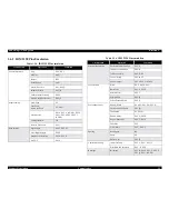
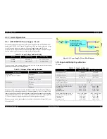
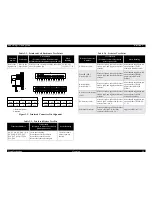
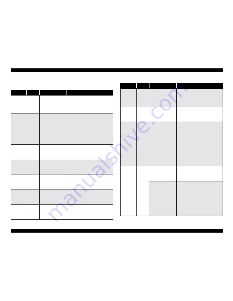
2.3.3.1
Main Components
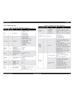
Table
2-6. Function of the Main Components
Component
Location
Name
Memo
CPU
IC7
TMP94C251
-
16 bit, 144 pin QFP
-
9.83MHz
-
Main controller
-
Detectors control
-
CR Motor Control
Gate
Array
IC4
E05B76NA
-
System Controller
-
Parallel I/F control
-
Option Type-B I/F control
-
Panel Switch, LED control
-
Printhead Control
-
PF Motor Control
-
CR Motor Current control
-
19.66MHz
-176
pin QFP
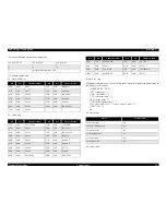
Program
ROM
IC8
EPROM
or OTP or
Mask
ROM
EPROM:
M27C800-10
(SGS)
equivalent
-
Program
-
8M bit
-16bit
DRAM
IC5
MSM514260C
(OKI)
equivalent
2CAS type
with
page access
function
-
Buffer and work area
-
4M bit
EEPROM
IC11
AT93C46
Atmel (2ms/
word
write)
-
Stores default setting and various
parameters.
-
1K bit
-SOP
8 pin
CGROM
IC6
MROM1:
44SOP
(600mil)
MROM0:
32DIP
(600mil)
-
CG
-8
bit
Reset
Circuit
IC8
Reset
IC BH6150F
Reset
Circuit 2
-
Reset IC
-
Drives minimum Low-Pulse 60ms,
Reset
signal.
-Detecting
Voltage 4.2 ± 0.2V
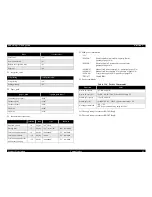
Head
Drive
Circuit
--
Tr
2SD2206A,
Di
S5688G ,
Tr
2SD2635 ,
Di
ISR139-400
-35V
± 6%
-Generate
head (24pin) driving wave
based
on the printing timing signal (CPU
output).
-
Reset: G/A output L (Head drive OFF)
Cooling
Fan
Circuit
Not
used 2SD2176
-35V
± 6%
-Rated
voltage drive
-On/Off
by G/A board
-Resistor
setting L:stop
Power
Supply
Control
Circuit
--
DTC124E
-At
energy-saving mode, this circuit
switches
power PSC signal to Open /
GND
by Tr.
-On/Off
by G/A board
-Resistor
setting L:ON (at reset) H: OFF
-Detect
the voltage by CPU A/D
ON voltage 22V/ Off voltage: 32.9V
-When
it detects OFF voltage, it uses the
adjusted
value by 35V drive voltage
adjustment
value.
-When
it detects ON voltage, it uses the
adjusted
value by 20V drive voltage
adjustment
value.
Eco-drive
Circuit
--
95V
charging circuit
-Boosting
chopper circuit
-Drives
by fixed pulse generated by
CPU.
-ON
3.0us Frequency 40us
95V
regular voltage
circuit
-Input
regular voltage type chopper
circuit
(for head current return)
-TL594
equivalent
-Rated
input voltage: +5V
-Input
voltage preciseness: +5V ± 10V
-Rated
input current: 0.053A
-Input
current range: 0A to 0.25A
-Output
voltage: +35V ± 6%
-OVP:
150V or less (output OFF signal
against
power supply unit.)
Table
2-6. Function of the Main Components
Component
Location
Name
Memo
Summary of Contents for LQ-570e
Page 8: ...C H A P T E R 1 PRODUCT DESCRIPTION ...
Page 46: ...C H A P T E R 2 OPERATINGPRINCIPLES ...
Page 57: ...C H A P T E R 3 TROUBLESHOOTING ...
Page 70: ...C H A P T E R 4 DISASSEMBLYANDASSEMBLY ...
Page 93: ...C H A P T E R 5 ADJUSTMENT ...
Page 101: ...C H A P T E R 6 MAINTENANCE ...
Page 106: ...C H A P T E R 7 APPENDIX ...
Page 127: ......
Page 128: ......
Page 129: ......


