


EPSON
LQ-570e/LQ-580
Revision
C
Disassembly
and Assembly
Disassembly
and Assembly
91
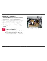
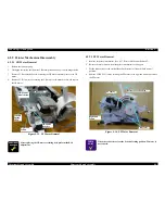
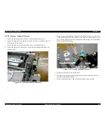
4.2.9.10
Ribbon Drive (RD) Assembly Removal
1.
Remove
the printer mechanism. (See 4.2.7 "Printer Mechanism Removal".)
2.
Remove
the upper head cable and the lower head cable from the printhead. (See 4.2.1
"Pre-disassembly
Procedures".)
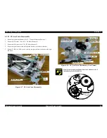
3.
Remove
the platen cover and remove platen. (See 4.2.8 "Platen Removal".)
4.
Remove
the hexagon nut, release lever, washer and the bushing parallel adjust.
Remove
the adjust parallel bushing. (See 4.2.9.8 "Carriage Assembly Removal".)
5.
Remove
the harness of PG detector. (See 4.2.9.4 "PG (Platen Gap) Detector Removal")
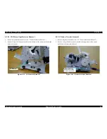
6.
Remove
the harness of HP detector from the left frame. (See 4.2.3 "HP (Home
Position)
Detector Removal")
7.
Remove
4 CBS (3x8, F/ZN) screws securing the left frame to the printer mechanism,
and
remove the left frame.
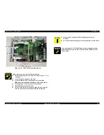
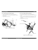
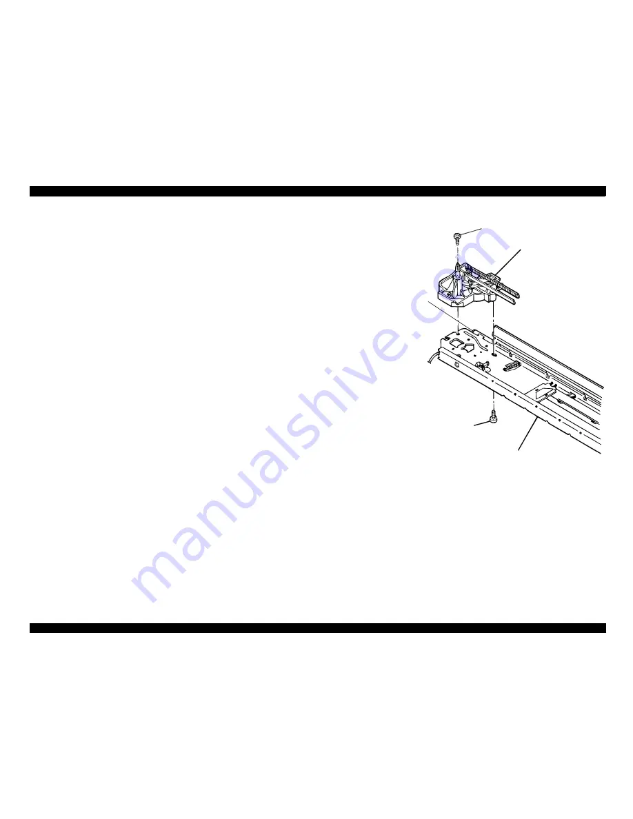
8.
Remove
CBS-Tight C(P2) (3x8, F/ZN) securing the ribbon drive assembly from the
top
and remove CBB (3x8) screw securing it from the bottom.
9.
Release
the ribbon dive assembly engaging with the drive roller assembly and remove
the
ribbon dive assembly.
Figure
4-28. RD Assembly Removal
C B S - T i g h t C ( P 2 ) ( 3 x 8 , F / Z N )
R i b b o n D r i v e A s s e m b l y
C B B ( 3 x 8 )
F R A M E , F R O N T
R O L L E R A S S E M B L Y , D R I V E
Summary of Contents for LQ-570e
Page 8: ...C H A P T E R 1 PRODUCT DESCRIPTION ...
Page 46: ...C H A P T E R 2 OPERATINGPRINCIPLES ...
Page 57: ...C H A P T E R 3 TROUBLESHOOTING ...
Page 70: ...C H A P T E R 4 DISASSEMBLYANDASSEMBLY ...
Page 93: ...C H A P T E R 5 ADJUSTMENT ...
Page 101: ...C H A P T E R 6 MAINTENANCE ...
Page 106: ...C H A P T E R 7 APPENDIX ...
Page 127: ......
Page 128: ......
Page 129: ......


